Questions often arise relating to the structure of a building in which an installation is being made. Very often, they have little or nothing to do with electronics, yet must be answered if a satisfactory installation is to be completed. They usually fall into one of two categories: those relating to running the interconnecting wiring between the various units of the system; and those connected with the placement and physical mounting of the equipment.
The first category includes the physical routing of antenna transmission lines, remote speaker lines and signal lines to components separate from the main installation. If you must run leads through walls, floors or ceilings, it is well to know what your drill is heading into. You could heat a client to the boiling point pretty rapidly by boring a neat 3/8-inch hole in a hot-water pipe or radiator steam line, and you'd give yourself a reasonably hot fist if you put the drill into a concealed ac power cable. By picking a bad spot for your hole, there is also the gloomy possibility that you'll be there till next Michaelmas trying to get through 6 inches of reinforced concrete with a steel I beam in the middle of it.
The second category includes those questions you'll need to answer if you're doing a built-in installation, whether it is to be sunk in or attached to the wall. Either way, you'll need a shrewd idea of how the wall is built and what is likely to be inside it, if anything.
Purely electronic questions such as hum pickup, electrical interference or undesired rf shielding due to the building are not the province of this section. Section 7 explains how to deal with them.
Basic construction
A bewildering array of materials and methods is used in building construction today. If the basic construction principles used were actually as varied as external appearances suggest, the subject really would be a hopeless morass. But fortunately, this isn't so.
In spite of our vaunted technology we are still putting up most of our buildings on the basis of mechanical principles that have been in use for a very long time. In fact, if we keep at it long enough, we may even catch up with the ancients and figure out exactly how Maya architects cut hard rock so well without hard steel tools, or how the Arch of Ctesiphon was really built.
This is by way of encouraging you to look for basic similarities underlying surface variations. We'll discuss some of the constructions in common use today but, if you encounter one that doesn't seem to conform to any of them, look for it to be a variation or combination rather than something out of deep left field.
Wood frame
In the country as a whole, there are more wood frame buildings standing than all, other types of construction put together. The vast majority of private homes are built this way, and so are a good many smaller commercial and industrial structures.
Fig. 1401 shows one type of wood framing (a method called balloon framing) which is part of the framing for a two-story residence. There are several other ways of working out light wood framing, but they are sufficiently similar so that for our purposes this one will do to illustrate the group.
This frame starts with the sill which is laid level on top of the foundation, and bedded in cement. The corner posts and studs rest on the sill and support the plate that runs horizontally across their tops. This plate in turn supports the roof beams or rafters.
The floor beams or joists for the ground floor also rest on the sill while the joists for upper floors are held on girts or ribbons that are carried on or attached to the studs.
Do you see these short pieces labeled firestop wiggling along more or less horizontally between the studs? If the void in the wall between studs isn't filled with insulation, they'll be there.
Their name explains their purpose, but to you they mean that you cannot fish cables inside the wall from ceiling to floor because they'll be in the way, unless the wall hasn't been closed yet. In that case, you can readily drill through them. Fishing leads later ally between wall surfaces is obviously also out of the question once the walls are closed, because of the studs.
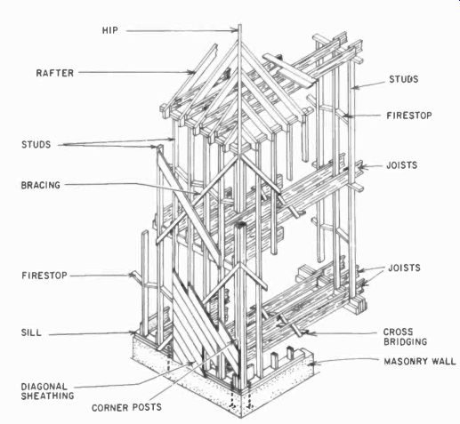
Fig. 1401. Balloon framing, one of several similar types of light
wood framing for residential and small commercial structures. (Architectural
Graphic Standards.)
------------------
Glossary of Architectural terms
Anchor: metallic belt built into masonry to hold facing materials
Blocking: fit with or mounted on blocks
Bracing: collection of timbers, metals, etc., used to support portions of the frame work
Casement: hinged window sash
Flashing: sheet metal coverings protecting joints and junctions of roofs with walls or chimneys
Furring: thin strips of board that provide level lathing or plastering surface
Header (or header block): brick or building stone positioned lengthwise across a wall
Hip: line of juncture of two sloping roof sides
Jamb: vertical framework members of door or window
Joist: main timbers that form a base for fastening floorboards and laths
Lath: thin, narrow wood strips used as a basis for plastering
Lintel: horizontal piece laid across the top of door or window jambs
Masonry: stonework
Mullion: wood or metal, vertical separating strip between panes of a window
Rafter: supporting timber holding roof covering
Sheathing: covering or outer layer of metal, wood or other material
Shingles: overlapping thin pieces of wood, asbestos, etc. used for covering roofs and sides of houses
Siding: boarding, metal, or composition forming the sides of a timber building
Sill: horizontal piece of member beneath a window, door, or other opening
Stool: window sill
Stud: vertical supporting timber in building walls
Veneer: thin sheet or layer of fine-grade covering material
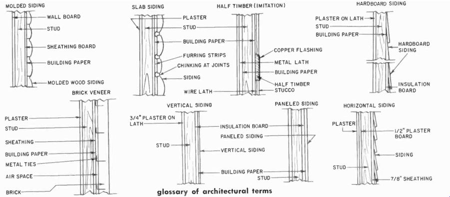
Fig. 1402. Various typical interior and exterior finishes for wood-frame
walls. Any interior can be used with any of the exteriors. (Architectural
Graphic Standards.)
---------------
Note that the floor beams or joists run the same way on the upper floor as on the ground floor. This means that if you need to know which way they run upstairs, you can look in the basement or crawl space under the ground floor to find out. The joists of upper floors will of course be hidden from direct view by the ceilings under them.
Both the exterior and interior finish of wood-frame walls can be treated in a variety of ways. Fig. 1402 shows a few. It makes very little difference whether the exterior walls are finished in shingle, siding, paneling, brick veneer or what have you. The only types you need to give second thought to are straight stucco and stucco with half timbers. In such cases, the stucco may be on metal lath. The lath could constitute quite an effective If shield even though the frame is wood. If so, it may be necessary to give the tuner an outside antenna.
In this type of construction, metal lath under the plaster of interior walls is not common, but on occasion it is used. So it is possible you could have a wood frame with wood exterior finish and still have metal lath in the wall under the interior plaster causing rf shielding. An outdoor antenna is again a possible requirement, particularly for FM or TV reception at medium or greater distances from the transmitter.
Plank and beam construction
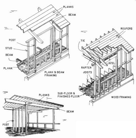
Fig. 1403. Comparison of plank and beam framing with conventional
wood framing. (Architectural Graphic Standards.)
A relatively recent development in small-home building is plank and beam construction. This method substitutes a few large structural members in place of the many small members used in conventional wood framing. The sheathing, roofing, and flooring boards are beefed up so that they really become structural members. Fig. 1403 shows a comparison between plank and beam framing and conventional wood framing. Due to the smaller number of parts required, the assembly time needed on the job can be cut down, reducing labor costs and the bad-weather hazard.
Interior finishing labor can also be reduced, giving additional savings.
Take note in Fig. 1403 of how the window opening is framed in each case. If you have occasion to sink built-in installation into a wood-frame wall or partition, you should frame in the area to be occupied by the system just the same as if it were a window area, as shown. This way, you don't destroy the structural integrity of the wall, and at the same time you provide yourself with a frame within which the construction necessary to house the equipment can be secured.
If you need to secure something to a wood-frame wall, the most positive method is to drive good hefty wood screws into the studs.
The problem is to find the studs! Normal spacing is 16 inches center-to-center, so try this first. Measure out from a corner 16 inches. Tap the wall with a padded hammer, and somewhere be tween 16 and 17 inches you should be over the center of the first stud. You should get a fairly solid thunk when you're on it, and more of a hollow boom when you're off it. Tap a few inches off on either side of where the stud ought to be, then tap for the stud. If there is a definite difference in sound, you're probably on it. But, to be sure, test by running a very small drill in where you think you've spotted the stud. If it goes in more than an inch and still seems to be in something solid--you're okay.
If you can't find anything at or near 16 inches, you must have some nonstandard spacing on your hands, so start at 12 inches from the corner, and tap your way out to 24 inches. It's got to be somewhere in there.
When the first stud is about 16 inches, the rest will conform.
But if the first one was not 16 inches, check carefully for the second one. If the second one is 16 inches from the first, the odd ball was just at the end. When the second one isn't spaced 16 inches, but matches the first, that spacing probably remains uniform. However, don't trust it. Tap for every stud you need to find.
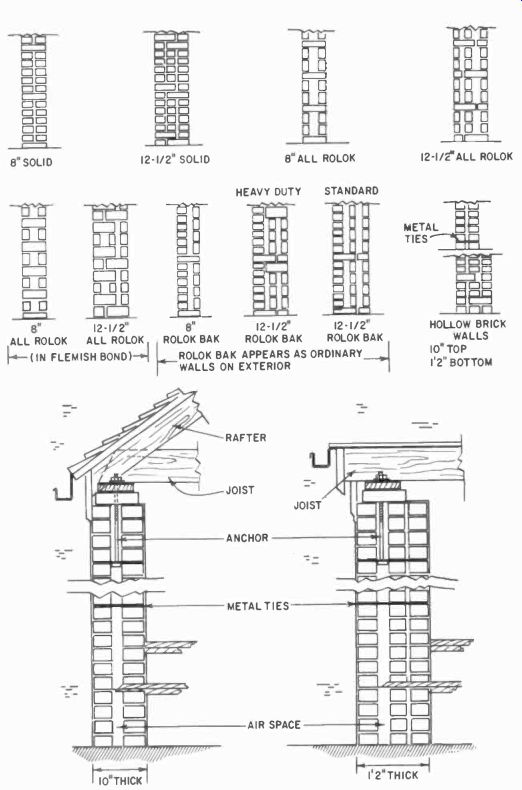
Fig. 1404. Various types of solid and hollow brick wall constructions.
(Architectural Graphic Standards.)
Masonry construction
In a general way, masonry construction covers the use of such familiar materials as brick, stone and the various kinds of building blocks: concrete block, clay tile, and gypsum or cinder blocks. In some cases, masonry walls are homogeneous; that is, one material only is used, while at other times two materials are sandwiched together to make up the full thickness of the wall.
In Fig. 1402, we have already seen one example of such a sandwich in the use of brick veneer on a wood-frame wall. This brickwork is certainly masonry, regardless of the fact that it is a surface veneer on top of a wood-frame construction.
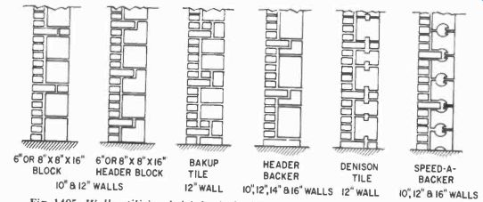
Fig. 1405. Walls utilizing brick backed with concrete block or clay
tile. (Architectural Graphic Standards.)
The difference is that in a construction that is entirely masonry, there is no wood frame in the walls. Fig. 1404 shows cross sections through several types of walls made entirely of brick. Note that some are solid and others hollow. If there is a way of telling by surface inspection whether the inside of a brick wall is solid or hollow, we haven't heard of it. To you it doesn't matter anyway.
You're not going to fish lines through the inside of the wall, even if it is hollow. And if you are thinking of piercing a hole of any size bigger than perhaps 1 inch through a brick wall, it can some times be done, but call in an architect or a structural engineer to work it out for you. Do not attempt to work it out yourself! If you have occasion to hang something fairly heavy on an all brick wall, or merely wish to attach a built-in unit to such a wall, you'll do well to use some type of expansion plug. Toggle bolts are not a good idea because, even if you know the wall is of hollow construction, you can't tell when you'll hit the hollow and when you'll hit a bonding course from the other side.
While brick can be used by itself to form a wall, it is often used in combination with concrete blocks or clay tiles. Fig. 1405 shows cross-sections of some of the various constructions possible.
If you can just manage to find out which material was used for the backing blocks (concrete or clay), then the actual internal con figuration won't matter for your purposes.
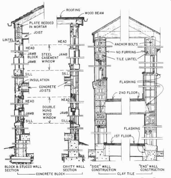
Fig. 1406. Typical sections of concrete block and structural clay
tile walls. (Architectural Graphic Standards.)
In concrete blocks, expansion plugs will hold perfectly well, so you needn't waste time and effort poking about to locate the voids in them. But you'll do well to avoid expansion anchors and to use toggle bolts in clay tiles. And take care to load the toggle bolts rather lightly. Clay tiles are designed to stand up under the kind of compression loading they get as a part of the wall, but not much of the kind of lateral pull they'll get from a toggle bolt.
Concrete block or clay tile can perfectly well be used by them selves without brick facing. Fig. 1406 shows sections of such walls.
They will often carry an exterior coat of stucco for appearance.
Obviously the absence of the exterior layer of brick is not going to change the fastening considerations regarding these walls one bit.
In combination walls of brick with block or tile and in walls of block or tile alone, observe the same caution about piercing large holes as you would in an all-brick wall. Get an architect or an engineer to plan the job.
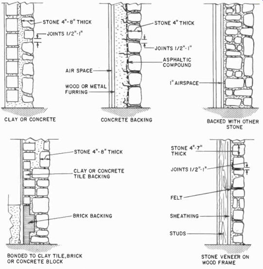
Fig. 1407. Common methods of using stone. (Architectural Graphic Standards.)
Probably the first type of construction to come to mind at the mention of the word masonry is stone. Like brick, stone is some times used alone to form a wall, and at other times either as a veneer over wood-frame construction or in combination with concrete block or clay tile. Fig. 1407 shows some of the ways stone can be used.
When you do run into stone work, it isn't going to change your life any. Most of what you have to do with a wall is related to the backing, and the majority of the stone you'll encounter will be backed with either wood frame, clay tile or concrete block. You know how to deal with them.
If you do have to attach something directly to stone, use expansion plugs the same as for brick, but be prepared to have a harder time making holes for the expansion anchors in stone. At times you'll run into some brutally hard stone. Then the carbide drill turned by a powerful, slow-speed hand drill is the installer's best friend. (And give it heavy feed pressure.) Or you may find it expedient to put the holes for the anchors in the mortar between stones wherever possible.
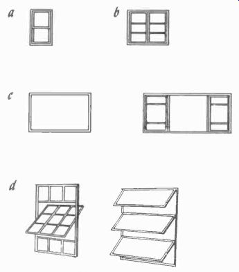
Fig. 1408. Common window types: (a) sash. (6) casement, (c) picture
and picture with side casements and (d) projected and awning.
Steel frame
Nowadays if a building is planned to be of really significant size, only two methods of holding it up are worth serious consideration. One of these is steel-frame construction.
You've doubtless seen the bare steel frames of office buildings under construction, at least from a distance. If you examined a number of them closely, you'd see wide variations in the structure of the members forming the frame, but the underlying principle remains the same. The entire weight of the building and its con tents is carried by the structural steel. This takes a good deal of steel, and steel is frequently an rf shield. The frame in itself might not be too bad, but by the time steel floor beams, studs and metal lath have been added, the shielding can become pretty complete. Add exterior curtain walls of aluminum paneling, and you have a pretty good screened room. The only real solution is an outdoor antenna, which may present difficulties in a large apartment building.
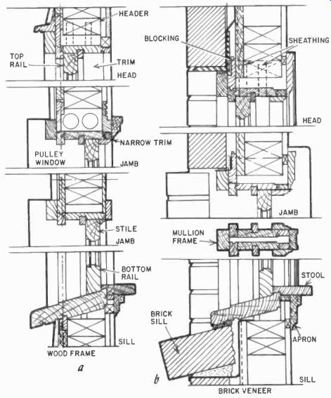
Fig. 1409. Installation details for double-hung wood sash windows
in (a) wood frame and (b) brick veneer. (Architectural Graphic Standards.)
Reinforced concrete
Here again, as with steel framing, the structural details can vary quite widely, but the basic method remains the same. A series of reinforced concrete columns support each floor, which is, in turn, essentially a continuous reinforced concrete slab.
Variations in size and placement patterns of the reinforcing bars depend on the sizes. uses and expected stresses.
In any event, it's also possible in this kind of construction to encounter shielding problems. The outside antenna is again likely to be required.
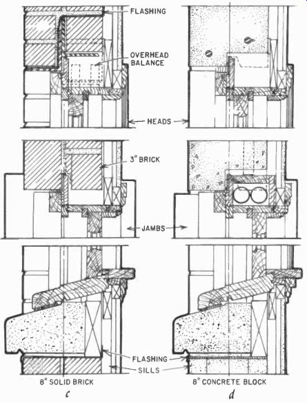
Fig. 1409. (continued) Details of double-hung wood-sash windows (c)
solid brick and (d) concrete block. (Architectural Graphic Standards.)
Typical construction details
Regardless of how a building is built, it must have doors and windows, floors and interior partitions. These are things you'll have to work through and around in installation work, so we'd better see how these things are normally handled.
Windows
The basic types of windows are: first (and most common), double-hung sash; second, casement; third, single- or double-glass picture; and fourth, projected or awning types (Fig. 1408). The old type that swings horizontally on a center pivot and the sliding types are so uncommon they are hardly worth mentioning.
All the common types are available in three materials: wood, aluminum and steel. And any of them can be mounted in any of the constructions we have discussed; wood frame, masonry, steel frame or reinforced concrete. In practice, wood windows are seldom used in steel-frame or concrete buildings. Steel sash windows are not as common as wood or aluminum ones.
Fig. 1409 shows details for double-hung wood sash windows in wood frame, brick-veneer, solid-brick and concrete-block constructions. Fig. 1410 shows aluminum double-hung sashes in wood frame and brick.
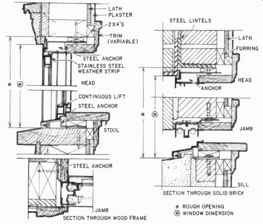
Fig. 1410. Aluminum double-hung sash windows in wood-frame and brick
constructions. (Architectural Graphic Standards.)
Fig. 1411 shows a wood casement in wood frame, and an aluminum casement in brick.
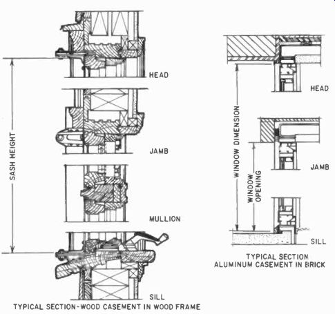
Fig. 1411. Wood casement window in wood-frame construction and aluminum
casement in brick construction. (Architectural Graphic Standards.)
Fig. 1412 shows steel casement used in various ways. There is neither space nor need to illustrate all the possible permutations and combinations you may encounter. From the viewpoint of installation work, a window is an opening in the structure of a wall that you may use to get through to the outside with a transmission line. The window details shown will cover the vast majority of those you'll see.
To make a hole for leads through the apron from the inside, start it just under the stool, and aim to come out just under the sill on the outside by angling your drill somewhere between 10° and 15° (Fig. 1413). The hole should always be angled down as it goes out to prevent water entering from outside through it.
After the leads have been run through, caulk the outside end of the hole as an additional precaution.
As you can readily see from the window-sill details, not all windows will permit you to do this. That's why we've shown so many. If you can't get the hole through properly, don't put it through at all. Either open the window and lay in a piece of flat lead on which the window can close or, if this won't work, get outdoors somewhere else entirely.
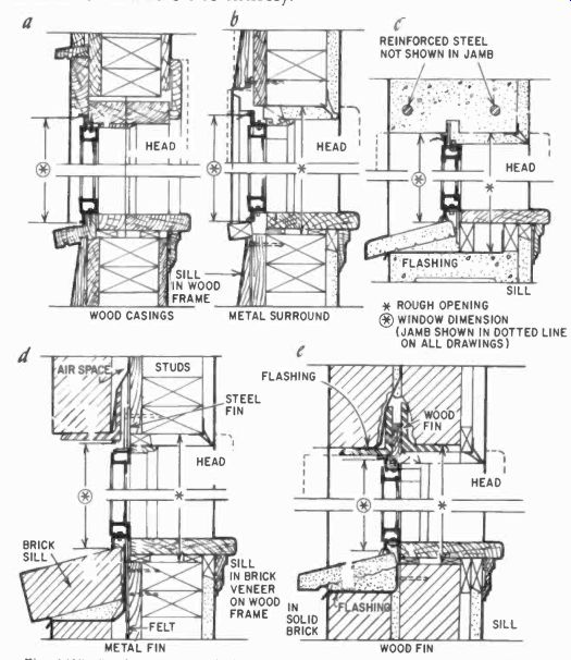
Fig. 1412. steel casement windows: (a and b) wood frame construction,
(c) concrete block or structural tile construction, (d) brick veneer
on wood frame and (e) solid brick construction. (Architectural Graphic
Standards.)
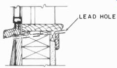
Fig. 1413. Section of window sill showing hole for leads in dashed
lines. (Architectural Graphic Standards)
Doors
In installation work, a door is usually a nuisance around which you have to run a wire. Fig. 1414 shows a detail of a typical interior door and frame. For our purposes, exterior doors are essentially similar.
If a door has wood trim, there is no problem getting a line around it by running up one side of the trim, across the top and down the other side. But if you've metal trim or no trim or madam considers a line up, across and down unsightly, there is another way. You can run the line straight across the bottom of the door opening. Unfortunately, this is usually done by the lazy method of stapling it alongside the door saddle. We consider this method dangerous, and therefore unsatisfactory. The door saddle should properly be removed, grooved to accommodate the line, and replaced with the line passing under it and thus covered.
A line stapled right alongside a door saddle does get some protection but, if you think about it for a moment, you'll agree it's really not much, certainly not enough for a permanent installation.
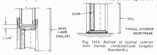
Fig. 1414. Section of typical interior door frames. (Architectural
Graphic Standards.)
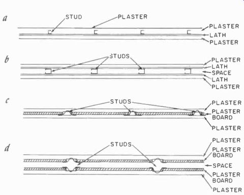
Fig. 1415. Interior partitions: (a) solid with metal studs and lath,
(b) hollow with metal studs and lath, (c) solid with metal studs and
plasterboard and (d) hollow with metal studs and plasterboard.
Interior partitions
The interior partitions in wood-frame structures are pretty sure to be wood-frame construction also. Stud spacing will be the same as for exterior walls, normally 16 inches on centers. Fig. 1402, showing cross-sections of frame walls, gives a variety of interior finishes as well as exterior. Either one or both sides of an interior partition wall may be finished in any of the various ways shown.
To attach something to such a wall, follow the same procedure as for attaching to an exterior frame wall. If you make an opening in which to flush-mount something, be sure you plan to frame it in with a header and sill just as if it were a window opening in an exterior wall. And check where the power wiring and plumbing seem to be going, before you decide finally on the location and size of the opening.
Wood-frame partitions will be found not only in wood-frame buildings, but also in a good many masonry structures: brick, concrete block and so on. The obvious reason is that they are cheaper and easier to put up than masonry partitions.
Where masonry interior partitions are used, they will be made of light building blocks: concrete, cinder or clay tile. Brick is very seldom used for this purpose.
Outside of the fact that masonry interior partitions are generally made of thinner blocks than are exterior walls, both masonry and wood-frame partitions are constructed in basically the same way as exterior walls. But there are several types of metal-stud and metal-lath partitions in use that do not resemble any type of exterior wall.
Fig. 1415 shows four of them. In Figs. 1415-a and-c, the solid types, are essentially similar to each other, as are-b and-d, the hollow ones. Methods for attaching to such partitions are obvious in solid walls, use expansion plugs; in hollow types, use toggle bolts. If you want to hang a cabinet completely unsupported except by the wall on any of these types of partitions, don't do it unless all you are hanging is one of the little half-pint speaker systems. These partitions won't take much of this kind of load. Not that they'll fall down, but they won't hold fastenings as well as some of the other types.