THE various types of manufactured hi-fi system components pose few serious technical problems from the installer's point of view. Nevertheless, it is useful to have an overall picture of just what may be encountered, and what may be anticipated as later additions to a system before you begin. Right away, it becomes desirable to clarify a few definitions before going into details. For our purposes, a hi-fi system is defined as meaning the entire collection of equipment that makes up the installation, even though all the various units that make up the whole may never be in operation at once. Thus, a simple system (Fig. 401) might consist of a turntable with its associated tone arm and pickup, a preamplifier, a power amplifier and power supply (either as one unit or separate), a speaker in its enclosure and the cabling necessary to connect these components in the proper manner.

Fig. 401. The simplest form of a single-channel high fidelity system
contains just three components: the record player, the preamp-amplifier
combination and the speaker system. For many installations, this is
all that will be required.
A component we define as any single unit of equipment, such as a preamplifier or record changer, that forms one of the building blocks of a system. This will simplify the discussion both here and in more complex matters taken up later. While we're at it, we may as well define the word part, also. This word gets abused often, so we'll use it to mean a specific part of a component or system that is not usually further sub-dividable, such as a vacuum tube, pickup, resistor or speaker.
System elements
Before we go on to detailed consideration of the various components that may be combined into a hi-fi system by the installer, it will be useful to consider a more versatile system than that of Fig. 401 and a fairly elaborate stereo layout.
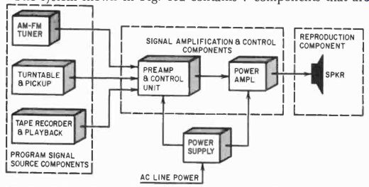
Fig. 402. Greater listening variety is afforded by using several different
program sources and a flexible preamplifier. The control section of
the preamp will per form a variety of switching functions, while use
of a separate power amplifier makes for easy replacement for future
expansion of system.
The system shown in Fig. 402 contains 7 components that are classifiable into 3 categories that will be recognized in all hi-fi installations. The three boxed at the left in the illustration are sources of program signals to be reproduced. Since the signal from such sources is not strong enough to drive the reproducer directly, and also usually requires some frequency response correction, it goes next to the components in the center box. Here, a switching circuit permits selection of the desired program signal, and equalizing networks and tone control circuits afford the needed adjustment of frequency response. Finally, the prepared signal is raised to the desired power level and applied to the reproducer, where the electrical signal is converted into sound waves and radiated into the listening area.
It doesn't necessarily follow that all monophonic systems are simple and stereo systems complex. The interconnections for the various components of a monophonic setup can be somewhat extensive. Fig. 403 shows a monophonic arrangement.
Regardless of how simple or elaborate a system is, it contains at least one component in each of the three categories mentioned,...
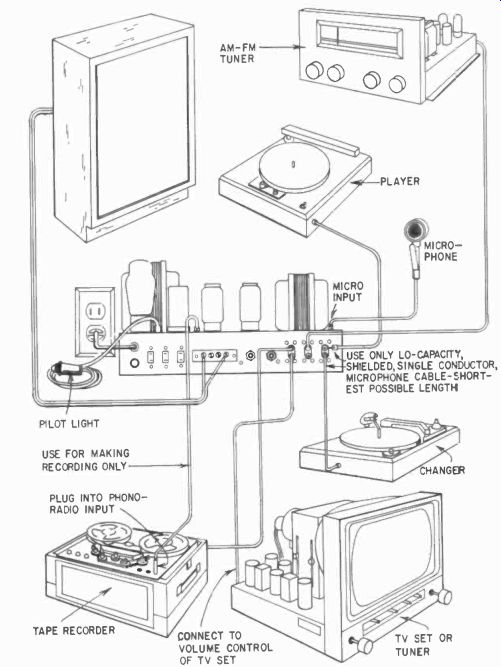
Fig. 403. A truly flexible preamp section should have many inputs,
both high- and low-level, tapped speaker outputs of several impedances
and a constant-level output for tape recording. Make primary connections
between program sources and amplifier with low-capacitance coaxial
cable.
Keep cable length as short as possible-preferably 18 inches or less. And when wiring, be on the lookout for a hot chassis. Avoid interconnecting transformerless TV sets.
...and two or more components are often combined in a single assembly. For example, the system shown in Fig. 401 has the pre amplifier, power amplifier and power supply combined in a single assembly. Many modest hi-fi installations use this combination type of component, particularly if space is at a premium. On the other hand, in elaborate installations such as the stereo system of Fig. 404, several components not often encountered may be found, such as resistance-capacitance frequency-divider networks.
In this stereo setup, the FM and AM tuners are shown as one mechanical assembly, although they must be independently tunable to be usable for stereo. The preamplifier and control units for the right and left channels are shown this way also.
Tuners for hi-fi systems
In order that high-fidelity broadcasts may be reproduced in the home with something like the quality of sound that the artists create in the studio, a radio receiving unit of somewhat special characteristics is needed at the receiving end. In a few cases, such a receiver may be a very elaborate component built into a cabinet with its own power amplifier and speaker. However, the most popular hi-fi component for this purpose is a specialized unit called a tuner. The name derives mainly from the fact that it tunes in the desired station while excluding undesired ones, amplifies the signal, demodulates the audio signal from the station carrier, and delivers the demodulated audio signal at a low power level to the next component in the reproduction chain, usually the preamplifier. A representative tuner is shown in Fig. 405.
Tuners may cover the regular broadcast band of amplitude modulated stations only, the frequency-modulation band only, or both. The last variety may be so constructed that only one of the two bands may be received at a time, or so designed that any station on either band may be tuned in simultaneously, but in dependently. This type is rapidly gaining in popularity, since it makes possible reception of stereo programs from those stations using the simultaneous AM and FM system of stereo broadcasting.
All-wave receivers
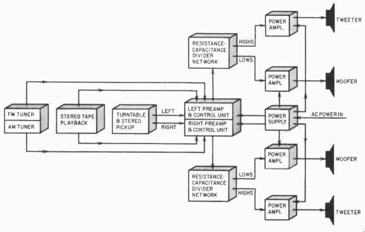
Fig. 404. A stereo system with several program sources demands a preamp
control section with many switching functions.
The all-wave receiver, once very popular, was so-called because it could receive the regular American broadcast band (550 to 1600 khz) and one or more high-frequency (shortwave) broadcast bands. These receivers fell from popularity for some years, but are now experiencing a renewal of listener interest, and you may occasionally find it necessary to integrate one into a hi-fi system.
Some receivers of this type are not very satisfactory as a high fidelity signal source without modification, due to sideband cut ting in the if amplifier, restricted frequency range in the audio ...
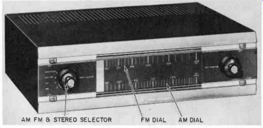
Fig.
405. This unit is a stereo tuner having separate AM and FM tuning units.
(Allied Radio corp.)
... section or excessive hum and noise. Others, however, offer variable if selectivity to meet the varying receiving conditions, and good-to-excellent audio channels. A number of US and foreign stations broadcast fine music programs with the world's best artists live or on recordings. Such programs, when coupled into a good hi-fi system (where some compensation can be made with the tone controls of the preamplifier to correct, at least partially, for high and low audio-frequency deficiencies in the receiver), can be very enjoyable, since they are unusually free of breaks for commercials.
Several representative receivers of this type are shown in Fig. 406.
Television sound channels
In a good many cases, the less said about piping the sound out put of a TV set into a hi-fi system, the better off everyone concerned is going to be. While TV stations are theoretically able to provide a high-quality sound signal over the sound FM carrier, a good many of them don't. They know quite well the quality of the average TV receiver's audio section, and the capabilities of the puny little 5-inch speaker inside the rattly metal cabinet. Once in a while, though, you'll get a client with a TV set providing a pass able audio signal from the detector, and once in a while TV stations will broadcast the Philharmonic. In such cases, piping the detector output into an input of the hi-fi preamplifier may be fully justified, particularly in a full custom installation, where the TV set can be integrated into the overall setup right from the start.
Pickups and tone arms
BROADCAST BAND SHORT-WAVE BANDS
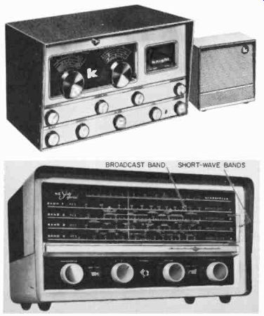
Fig. 406. All-wave receivers of the type used by hams and short-wave
enthusiasts can be incorporated as a program source in a high-fidelity
system. (Upper photo: Allied Radio Corp. Lower photo: National Radio
Co., Inc.)
Perhaps the most critical element in the reproducing chain between the wiggly groove in the record surface and the strains of the Philharmonic emanating from the reproducer is the pickup or cartridge. Few consumer items require such excellence in design and manufacture, or such a combination of delicacy and ruggedness.
All pickups do essentially the same job. They convert the small departures of the record groove from a perfectly smooth spiral path in the record material into an audio-frequency electrical signal almost the exact electrical equivalent of the signal applied to the cutting head in the studio. Such a device for converting one form of energy into a precise equivalent in another form (in this case mechanical to electrical) is called a transducer. Modern pickups (Fig. 407) are greatly improved over their predecessors of 10 or even 5 years ago, thanks to concentrated research effort in the industry in response to continued public support of the hi-fi market.
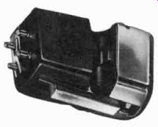
Fig. 407. Example of a typical stereo cartridge.
No one transducer principle has so far shown itself to be outstandingly superior for solving the pickup problem. At present, excellent pickups operating on piezoelectric, variable-reluctance, electrodynamic and frequency-modulation principles are available, and the use of magnetostriction and the strain gauge. (vari able resistance) principles is by no means dead. The principal problem this variety of pickups presents to the installer is that of making sure the pickup is working into the optimum load impedance in the preamplifier input circuit, and that the ambient conditions are not such as to injure the unit or degrade the quality of reproduction. Piezoelectric pickups employing Rochelle salt as the sensitive element are soon damaged by extremely humid or dry conditions (fortunately, not in the range found in the average living room), and by even short exposures to temperatures above 115°F. Unfortunately, this can be a snag, since the rising air column over power or rectifier tubes in a hi-fi installation can easily exceed this limit.
Piezoelectric pickups using a ceramic element such as barium titanate are relatively immune to humidity and temperature problems, but provide a lower electrical output for a given groove modulation.
Electrodynamic and variable-reluctance pickups are usually more troubled by strong hum fields such as may exist around some turntable motors or exposed ac wiring in the room. Iron turn tables may also cause trouble with such pickups, either through hum induction or a change of stylus pressure because of magnetic attraction. The ribbon type of electrodynamic pickup is some what more delicate mechanically than some other types, although all good pickups should be handled carefully.
Pickups in which the frequency of an rf oscillator is modulated by action of the vibrating stylus are somewhat susceptible to direct electrical interference, and also to an extent by drift of the basic oscillator resting (no-modulation) frequency, although this problem has been much reduced in recent years.
All pickups employ a certain amount of mechanical damping Fig. 408. A wide variety of pickup arms is available for manual turntables.
This type of arrangement gives best record reproduction and longest record life. (Stromberg-Carlson Co.) to smooth the response, particularly at the two principal resonances that wall in the audio range. Improvements in damping materials in recent years have substantially reduced the effects of age and high ambient temperature and low humidity on pickup damping blocks. However, these effects should not be forgotten, particularly if a good, but old pickup, is a part of an installation.
In particular, any pickup using natural-rubber damping blocks should be regarded with suspicion if it is more than a year or so old, or has been exposed to high temperatures.
Tone arms and turntables
The partners of the pickup in the act of transducing the record groove wiggles into an electric signal are the tone arm that holds the pickup, and the turntable or record changer that spins the disc. Both these elements of a hi-fi system are equally important, but the tone arm has a more direct and intimate relationship with the pickup. Tracking error, stylus pressure and the arm and record material resonances are directly affected by the design of the arm and its interaction with the pickup in operation. For this reason, some makers have developed arms specifically for use with a certain model pickup. In general, best results with these pickups will be obtained by sticking to the recommended combination. A number of excellent tone arms are available, however, (Fig. 408) that permit a wide range of adjustment to suit various pickups, and have acceptably low pivot friction and satisfactory resonance characteristics. The installer must give the same careful consideration to the maker's recommendations for mounting, leveling and similar matters as he does to any other part of the installation process. An error of 1/16 inch in placement of the tonearm turning center with respect to the center of the record spindle can cause a significant increase in tracking error, particularly with short pickup arms.
The turntable itself is a critical element in the reproduction system, particularly in a system good enough to really reproduce hum and rumble if they are present in significant amounts. It is difficult to design and manufacture a mechanical drive that affords the exceptional constancy of angular velocity, acoustic quietness, and freedom from vibration required of even a good monophonic turntable. When these stiff requirements are aggravated by the additional requirement that vertical vibration also be held to a very low level to afford good stereo reproduction, the problem becomes acute.
TONEARM COUNTER-BALANCE RUBBER MAT TURNTABLE TONE ARM HANDLE SELECTOR CONTROL ( ON-OFF REJECT) MA IN PLATE
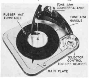
Fig. 409. Record changers currently avail able have many features
formerly found only in professional-quality equipment.
This model has an adjustable weight on the tone arm and a handle for manual operation. (Webcor, Inc.)
Good turntables are manufactured, but to achieve high quality throughout a production run is expensive. From the installer's point of view, making the cutout and installing and leveling the table and the tone arm are the chief concerns. Bear in mind, however, that the greatest care in this process can be nullified by a sloppy bearing fit in the drive mechanism of a spanking new turntable.
Record changers
The installer must face the fact that record changers are going to be around for a long time, even though the vibration, rumble, wow and various other ills that afflict them are usually much more prominent than in straight turntables. In typical changers (Fig. 409) in the popular-price range, such factors are not intolerable, but must be given the same attention recommended in connection with turntables. When the equipment is tested after installation, take special care to check for excessive rumble and other objectionable characteristics. If this is not done, the installer may be blamed for something beyond his control. Fortunately, reputable makers are always willing to correct a condition in an individual unit that does not meet their published performance figures.
------------------
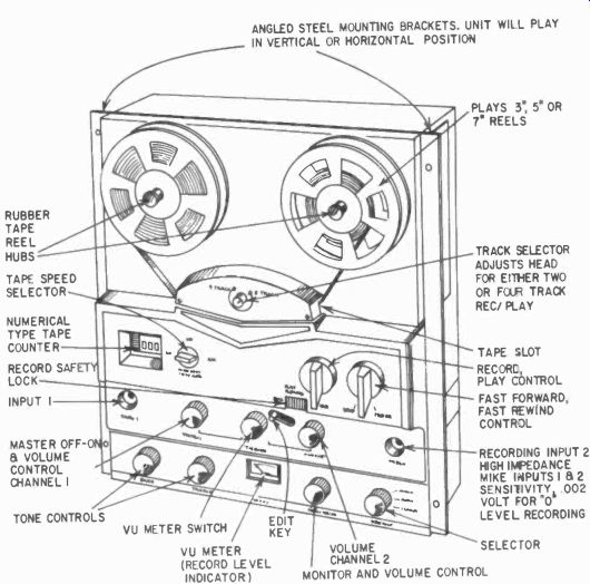
Fig. 410. Stereo tape recorders are becoming highly versatile and
complex. The home-model tape deck shown here will record and play back
two stereo channels and will play back pre-recorded four-track tapes.
(Webcor, Inc.)
---------------------
The cutout template, mounting instructions, clearances above and below the mounting board, and other necessary specific in formation for a given changer are provided in the manufacturer's literature, usually in a sheet or pamphlet accompanying the equipment. Follow the instructions carefully. Overlooking a single point, such as removal of inconspicuous packing or holddown ties used for protection in shipment, can lead to an exasperating waste of time later.
Tape recording and playback equipment
The use of tape recorders and tape players has not shown quite the phenomenal growth of disc high fidelity. Nevertheless, it continues to increase, particularly among audio hobbyists and the wealthier general hi-fi audience. Such equipment (Fig. 410) comes in a large variety, from completely self-contained midget portable units powered by batteries to large, rack-mounted professional equipment. Of course, the tape playback signal from any type can be put into an input of the hi-fi preamplifier and reproduced over the system. But you'll hear some pretty weird sound if the proper frequency compensation is not provided, and impedance matching and noise can be problems, too.
Many tape machines come complete with preamplifiers for recording and playback that provide the correct compensation for the tape heads used in the machine. With such equipment, the installer's problems are considerably simplified, as these preamplifiers usually afford the requisite sensitivity for microphone input, and an audio output level about equal to that of a good tuner. However, beware the noise, hum and interference-pickup troubles of a low-priced tape machine played through a good-quality hi-fi system. The proud owner will hear things he never dreamed was on the tape of his inexpensive little portable when listening to it on the small built-in speaker.
The actual installation of tape equipment is no more difficult than putting in a turntable or changer, but remember that the controls of a tape machine will be used a lot more often than those of some other parts of the system. For this reason, it should be positioned for convenience. Fumbling with half-visible knobs and threading tape reels deep in the recesses of a cabinet is a chore that will cause the customer to remember you with displeasure.
Preamplifiers
Of all the hi-fi components, probably more genuine advance in design has been achieved in preamplifiers than in any other.
This opinion may sound surprising, but it is based on considerable field experience. Even some relatively inexpensive modern pre-amps offer features that were well-nigh unattainable 10 years ago.
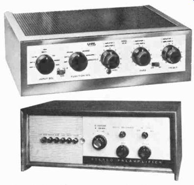
Fig. 411. Preamplifiers must perform many functions in a stereo system.
Complex switching systems take some of the brainwork out of operating
the rig, but a customer can be frightened by "all those knobs" if
he doesn't understand their purpose. (Upper photo: Electronic Instrument
Co. Lower photo: Altec Lansing Corp.)
This has come about partly through improvements in circuitry, but more because of advances in the design and manufacture of vacuum tubes, resistors and capacitors, and the advent of printed circuits, transistors and other semiconductor devices. In representative preamps now available (Fig. 411), hum, noise and in stability are well below the tolerable maximum limits for good performance with the other components of a system.
In addition, modern preamps provide a far greater and more precise control over frequency response, input switching and impedance for various input devices than was formerly available.
For the installer, preamplifiers are usually an easy item to handle.
The main consideration is to position the unit so that manipulation of the controls is easy and convenient, and the input and output connections are protected from accidental detachment.
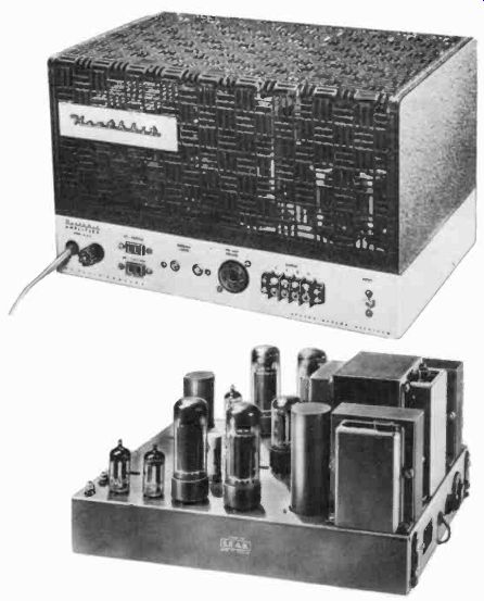
Fig. 412. The power amplifier is your hi-fi system's workhorse: (a)
a typical single-channel amplifier and (b) a stereo power amplifier.
Both units must be used with appropriate preamplifiers. (Upper photo:
Heath Co. Lower photo: British Industries Corp.)
Power amplifiers
Modern power amplifiers leave very little to be desired, as far as performance is concerned, and definitely provide more clean watts per dollar than was ever before available in good-quality audio. This has come about partly through the development of new tube types, such as the 6551, KT88 and others, and partly because of wider availability of really good output transformers.
Oddly enough, the most important feature of the celebrated Williamson amplifier was the relatively tough specification written for the output transformer. Only with a transformer of such superior frequency and phase characteristics was the amount of negative feedback used by Williamson feasible. As to the use of feedback itself, this was common in high-quality professional audio equipment even during the mid-30's.
For the installer, power amplifiers are most likely to be of concern when considering ventilation, heat radiation, size and weight factors. Since adjustment of the power amplifier is seldom required, it can be located in the less accessible part of a cabinet or shelf, but don't slight the air circulation problem. The run of signal and power wiring should be inconspicuous, and it is well to hold the length of cable from the power amplifier to the reproducer to a reasonable minimum. But, in the average home, this is not likely to be a critical factor (Fig. 412).
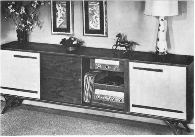
Fig. 413. An integrated stereo system is frequently very bulky and
may require extensive rearrangement of living room furniture. (Bogen-Presto
Co., A Division of the Siegler Corp.)
Reproducers
The speaker and cabinet or enclosure combination that makes up the reproducer is one of the most critical elements in any hi-fi system. The reproducer is a transducer in that it converts the electrical signal provided by the power amplifier into sound waves radiating into the listening area. Other things being equal, dollars and care expended on the transducing elements in the hi-fi chain (the pickup and reproducer) will show more net return in quality than if spent anywhere else. For the installer, some caution is in order if the job calls for putting speakers into an enclosure that is a part of the structure of the building. The factors involved are discussed in later sections. It is enough now to remember that they warrant respect.
Where the enclosure is a free-standing cabinet, the job is usually straightforward, even though the speaker is to be put into the cabinet as part of the job. Usually the maker's literature on the cabinet and speaker will provide any necessary details, such as ...
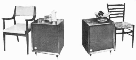
Fig. 414. To avoid
major reorganization of the living room, smaller speakers, conveniently
placed, can act as end tables. Be sure to insulate porcelain-ware
and other knick knacks against vibration. (R-J Audio Products. Inc.)
... the required size of the mounting-board hole. If the enclosure is a completely assembled unit, the problem resolves itself into one of placement for the desired acoustic and visual effect (Fig. 413).
The run of cable to the power amplifier can usually be handled inconspicuously along the upper edge of the baseboard, under a rug or even under the floor if there is a basement.
The trend in enclosures toward smaller, completely assembled units (Fig. 414), has been sparked in part by the modest dimensions of many modern homes and apartments. From the installer's viewpoint, this simplifies the job still further, since placement atop a bookcase or even on a shelf in an existing piece of furniture is entirely practical.