THE procedures for testing preamplifiers are quite similar to those for basic amplifiers. The principal differences consist of variations in the precautions necessary to insure that the measurements mean what they say. The section on basic amplifiers dealt with an amplifier without any frequency-compensating device, either equalization or tone control, and with an input of line level (that is to say, in the region of 1 volt, possibly as low as 0.1 and not higher than 2, such as would normally be delivered by a preamp).
Quite a number of high-fidelity amplifiers incorporate the functions of both preamplifier and amplifier in a single unit for purpose of economy. Such units can either be tested in .two "halves" or as an entity. The principal difference between testing a preamplifier by itself and measuring the characteristics of a complete amplifier which includes both functions is that, from the preamplifier, one measures the output voltage delivered to a basic amplifier while, in the complete unit, the output will be measured across the dummy load for the power amplifier section.
Frequency response
The procedure for checking the frequency response of a pre amplifier in its flat position is precisely similar to the method adopted for basic amplifiers. It is, however, even more important to be sure that the measurement technique does not introduce spurious effects, such as a ground loop formed between the instrument and the amplifier producing hum. This is likely to be more difficult to control because of the much lower level employed at the input of a preamplifier. Therefore it is important to practice looking at what you measure with the aid of a scope.
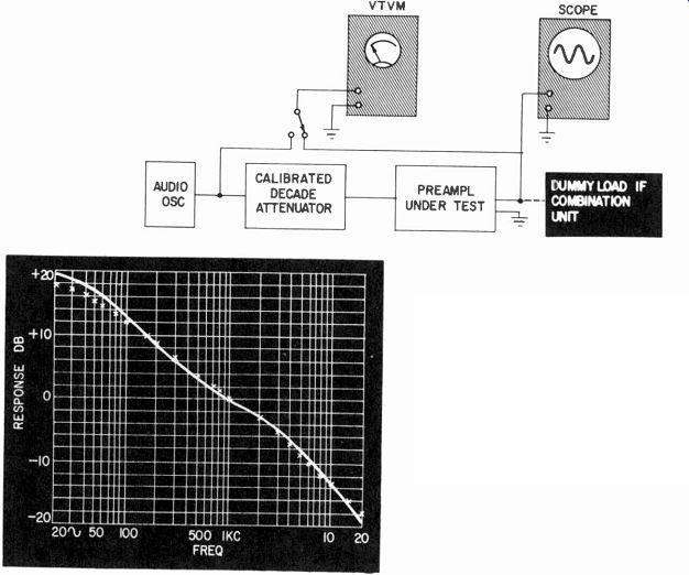
Fig. 601. Method for checking the equalization characteristics of a preamplifier.
A gain characteristic curve can be plotted.
When measuring frequency response with equalization characteristics or tone control circuits included, the question of level must be considered. For example, some methods of measurement may insert a constant input voltage and measure the frequency response by plotting the output voltage. This often is an unsatisfactory procedure because the large voltage output required at the low-frequency end, to get a measurable voltage output at the high-frequency end, will drive the preamplifier into distortion.
In deciding how to measure characteristics such as this, the purpose of the frequency compensation provided must be under stood. In an equalization characteristic, low-frequency boost is provided because low frequencies are de-emphasized in the input signal. In phono equalization, the low frequencies are deficient in a velocity pickup because of the 500-cycle turnover of the RIAA characteristic. So the playback has to receive a 6-db-per-octave boost below this frequency.
Similarly, pre-emphasis is provided on the record for frequencies above 2,120 cycles to improve the signal-to-noise ratio in this region. This produces a boost of the high frequencies in the input signal as compared with the 1,000 cycle reference point.
Therefore the purpose of equalization, as well as boosting the low frequencies, is to cut down the high frequencies so the overall response of the preamplifier comes out flat. This being the case, the method of measuring the frequency response of a preamplifier with its equalization characteristic requires that the output voltage be maintained at a constant level.
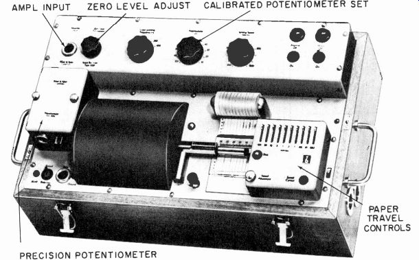
Fig. 602. A servo-type recording voltmeter, useful for automatic plotting
of response curves. (Courtesy Bruel & Kjoer)
Using a decade attenuator at the input of the amplifier is quite satisfactory for this purpose. The input and output voltages (input to the attenuator and output from the preamplifier), are maintained constant and the gain characteristic of the amplifier is plotted by reading the values from the attenuator (Fig. 601).
Where there is a higher gain, such as at the extreme low-frequency end, there is also a higher attenuation and consequently the amplifier input voltage is correspondingly reduced.
It is advisable to look at the signal measured at the output because the extreme attenuation can reduce the signal to a point where noise or some other component is measured instead of the frequency applied at the input. Where the response curve of production preamplifiers must be taken in routine fashion, it may be advantageous to use an automatic response-checking instrument (Fig. 602). However, a modification is needed if the output level is to be maintained constant.
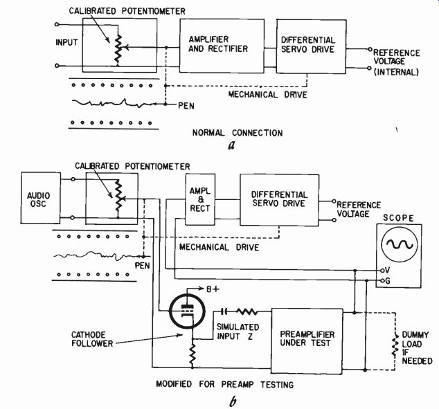
Fig. 603. Modification of the basic circuit of a recording voltmeter to permit
plotting the curves at constant output voltage rather than constant input voltage.
The instrument measures the variation in voltage at the output.
It is necessary to transfer the instrument's calibrated potentiometer from the output to the input circuit. The potentiometer is servo-coupled to the recorder and this mechanical coupling must be retained. But, electrically, the potentiometer is placed to work as the input attenuator to the preamplifier (Fig. 603).
Appropriate matching or isolation arrangements may be necessary if the input impedance of the preamplifier loads the attenuator and invalidates its calibration, as may happen with relatively low-impedance inputs intended for magnetic cartridges. Then a cathode follower can be interposed between the potentiometer and the preamplifier input, a suitable padding resistor being applied between the cathode follower and the preamp to simulate the input impedance required by the preamplifier.
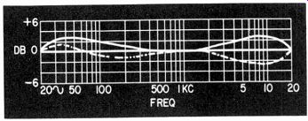
Fig. 604. Possible deviation from flat frequency response (solid and dot-and-dash
curves) when tone controls are set for equal gain at three points: 20, 1,000,
and 20,000 cycles.
The preamplifier output is connected to the point in the recorder circuit where the potentiometer tap is normally connected.
This enables the servomechanism of the recorder to adjust the input to the preamp so its output remains constant and the curve plotted indicates the precise adjustment of the input at all frequencies. In this way a curve will be plotted equivalent to that which will be taken by the manual method, adjusting the output of all frequencies to a constant level and measuring the attenuation necessary to do this.
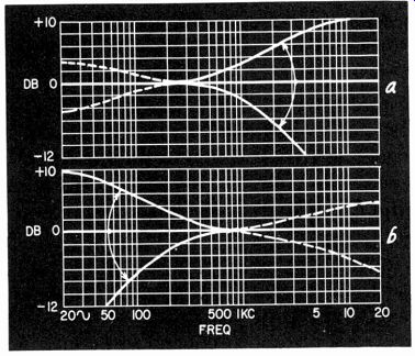
Fig. 605. Checking for possible interaction (dashed lines) between bass and
treble tone controls.
Modern equipment usually has at least two tone control knobs, one for bass and the other for treble. Measuring the overall performance of a tone control system can become quite complex. The best method is to determine how close to a flat response the tone control provides. To do this, adjust both controls until the gain measures the same at, say, 20, 1,000 and 20,000 cycles, or whatever extremes of frequencies the preamplifier is intended to handle, as well as the 1,000-cycle reference.
Having adjusted the tone control circuit so spot measurements of gain at these three points give the same answer, the complete frequency response can be taken. It is sometimes erroneously concluded that, having set up a tone control to achieve the same gain at three spot frequencies, the response must automatically be flat.
Unfortunately this is not always true, and many tone controls in the nominally flat position produce deviations of the kind shown in Fig. 604.
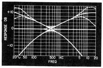
Fig. 606. Checking for interaction between controls when both are moved away
from flat position together.
After the response in the nominally flat position is determined the next step is to leave the bass control in the flat position and check the overall response with the treble control at maximum and minimum. Then restore the treble control to its nominally flat position and check the overall response with the bass control at maximum and minimum.
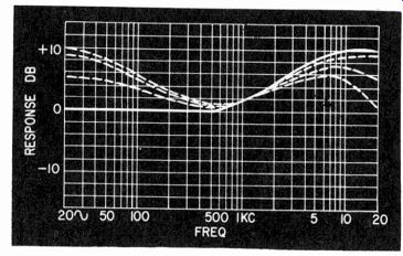
Fig. 607. Deviation when both, controls are at extreme setting (dot-and-dash
curve) may occur suddenly in the last few degrees of the bass control (short-dash
curve) or more gradually (long dash curve). Solid-line curve shows treble control
with bass control at level.
This reveals any possible interaction of the control varied on the one left at its nominally flat position (Fig. 605). The remaining thing to check is possible interaction between controls in other positions. This can be done (for extreme conditions at any rate) by taking the response with both controls at maximum, both controls at minimum and then with one each way (Fig. 606).
If there is serious interaction at some point, where it would not normally be expected, determine whether this extreme interaction takes place progressively or whether it is only an effect that shows up in the last few degrees of rotation of one of the controls (Fig. 607). This will depend upon the relative values of the circuit components.
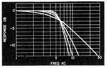
Fig. 608. Ideal response variation of variable-slope turnover type of control.
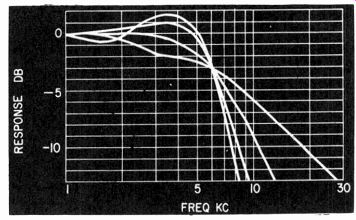
Fig. 609. Some variable-slope controls may produce undesirable peaking.
Some preamplifiers come with a special tone control intended for playing old records which takes the form of a variable low-pass filter. Sometimes only the frequency at which this filter turns over can be varied and sometimes both frequency and slope are adjustable. A representative series of responses should be taken to deter mine that the filter behaves at least approximately according to specifications. Often the curves published for such filters look very ideal with a turnover point that stays constant, and the slope adjustment varies the rate at which attenuation takes place above turnover (Fig. 608).
When the actual instrument is measured, however, the slope adjustment may affect not only the attenuation slope above turn over but may also introduce undesirable peaking and other variations in the response below the turnover frequency (Fig. 609).
The only way to explore such possibilities is to take a fairly large number of representative characteristics at different frequency and slope settings to see just how the circuit behaves.
There are two types of loudness control and the method of checking depends upon which is used. One uses a continuously variable control so the loudness control can be used in place of the older "volume" control. In this case, check the frequency response at a number of representative levels on the control.
First, take the response with the control wide open and then check the level so it is, say, 10 db lower at 1,000 cycles and take another response. Repeat this procedure for successively lower levels at intervals of about 10 db.
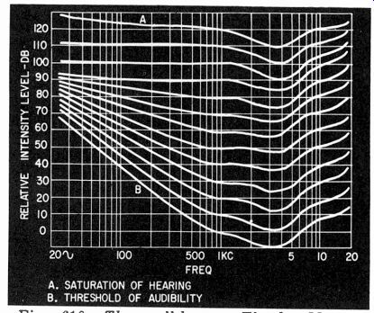
Fig. 610. The well-known Fletcher-Munson loudness contours on which the theory
of loudness controls is based. Each curve represents a different phon level.
The alternate form of loudness control uses fixed values with a switch, marked "low" "medium" "high" or "volume" and "loudness", relying on the gain control for minor loudness adjustment.
In this case the response in the fixed positions will be taken.
Some engineers are sticklers for making the loudness control give a response as close as possible to the Fletcher-Munson characteristics (Fig. 610). At the low-frequency end this procedure is probably justified because the loudness contour characteristics are reasonably representative of general acceptance. But at the high-frequency end the Fletcher-Munson characteristics are average curves from which individual ears are likely to deviate quite considerably. Consequently, there seems to be little point in going to great engineering trouble and expense in duplicating the high frequency end of the Fletcher-Munson characteristics.
If the particular kinks in these curves are to be reproduced, as a frequency response, considerable electronic circuitry is needed. It is important to realize that the curves at the high end of the Fletcher-Munson contour diagram run very nearly parallel. For this reason, it is not necessary or even desirable to compensate for the wiggles in the Fletcher-Munson curves because these are common to all characteristics. The loudness compensation is required to take account of the difference between individual contours and not their actual shape (Fig. 611).
What is more important than the precise high-frequency correction is to endeavor to get the steeper slope indicated at the low-frequency end for general effect there. Some are altogether too critical in adjusting loudness contours. If the response deviates from the Fletcher-Munson characteristics for the appropriate loudness contour by as much as, say 2 db, this must be corrected. On the other hand, many loudness controls go to the opposite extreme and make no attempt to achieve the kind of contour provided by the Fletcher-Munson characteristics even at the low-frequency end.
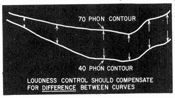
Fig. 611. The important thing in loudness compensation is to equalize for
difference between loudness contours.
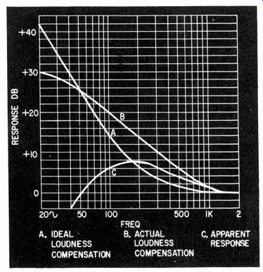
Fig. 612. The result of incorrect loudness compensation: over-emphasis of
middle-low frequencies and loss of extreme lows.
In the vicinity of the threshold of hearing, necessary for low level listening, the Fletcher-Munson contour in the low-frequency region has a slope of approximately 18 db per octave. If a slope approaching this order is not achieved, then the result of the loudness control will be an apparent middle-low-frequency heaviness (in the region of 100 to 250 cycles). Because the boost for the extreme low end is too gradual, the middle-low end will receive more boost than it should (Fig. 612). This adds an unnatural coloration to low-level music.
Some loudness controls make no variation in the high-frequency response at all with level. Actually the Fletcher-Munson contours for the high end do not justify a very large compensation. The most that is necessary is a gradual "lift" of between 3 and 10 db.
Most recordings sound balanced if played at approximately a 70-phon level because this is the level at which they were recorded.
Consequently this level should not have any loudness compensation in a preamplifier. The level at which the program is played must be adjusted (by a gain control and not a loudness control) so the level at which an uncompensated program is played comes out at about 70 phons. Then, as the loudness control turns the gain down, compensation should be made for the difference between the Fletcher-Munson curve at the precise level being played and the contour for 70 phons.
In the fixed type loudness control, "high" plays flat, "medium" introduces compensation for about 15 db and "low" for about 30 to 35 db. The loudness switch also introduces necessary attenuation.
On this basis, the high-frequency compensation will never need to be more than about 10 db at the extreme high end, of extremely gradual slope. Even this, in fact, is quite uncritical. Some may provide no more than a maximum compensation of 6 db while others may give as much as 12 or 14. This becomes somewhat a matter of individual preference since ears are not sufficiently consistent to warrant deciding on one or another.
Gain and sensitivity
Before we leave the question. of frequency response, it is well to measure the gain of the system, presumably at the nominal reference frequency of 1,000 cycles. In measuring the gain, which goes along with the sensitivity, it is important, in any amplifier where the gain control or loudness control is later than the first stage, to determine the range of sensitivity which the amplifier can satisfactorily accept.

Fig. 613. Block schematic of typical well-designed preamplifier, showing points
at which distortion can occur, according to the level of operation.
In discussing basic amplifiers in which the gain control is usually a potentiometer before the first-stage input, this is not of great importance. It is difficult, of course, for the average potentiometer to accept 100 volts input and apply 0.25 volt to the grid of the first tube. This is probably a greater range than the potentiometer will accept and the 100 volts may readily burn out the low-rated potentiometer with audio taper, used for the input control. But a range up to say 10 volts, which is more than 20 db (and may be as much as 40 db) higher than the nominal input for the amplifier, can usually be handled by a control in this position.
But when the gain or loudness control is somewhere in the middle of the amplifier, this means the earlier stages have to handle the full input without attenuation. So it is important, not only to know the maximum sensitivity of the amplifier, but also the maximum input it can handle without distortion (Fig. 613).
1 millivolt at the input, with the gain control wide open, may give the full power output in the case of a combination amplifier, or the rated voltage output in the case of the preamplifier. The gain control may be located at a position where the level is say 0.5 volt. Perhaps the stage that feeds 0.5 volt to the gain control receives an input of 100 millivolts and is capable of handling up to 1 volt before distortion is encountered. Working backward, this means the input can be 10 times the value required at maximum sensitivity before distortion will occur at this stage.
It is not necessarily the stage immediately before the gain control that will run into distortion. This depends upon other factors.
Usually the equalization controls come after the first stage of a preamplifier and the distortion may occur in the first stage, due to the large amount of attenuation in the equalizer. However, this possibility must be considered in combination with the normal level accepted by the input at different frequencies.
If equalization gives a 20-db boost to the low frequencies and 20-db attenuation to the high frequencies, then an input of 20 millivolts at 1,000 cycles should be regarded as commensurate with an input of 2 millivolts at 20 cycles or 200 millivolts at 20,000 cycles.
The easiest way to check this is to adjust the gain control to different settings and take frequency runs at each setting, observing at the same time possible distortion. In this way the highest input level (or the lowest position on the gain control that can be operated), can be determined before distortion occurs at some frequency with the tone controls set for flat position. The frequency response will be taken in each case so as to produce the nominal output of the preamplifier.
The loudness control cannot be used for the same function as a gain control-to adjust for different input levels received by the preamplifier. This will result in what is termed scale distortion, because the program will be played according to the wrong loudness contour for the level delivered by the preamplifier. When the loudness control, properly used, is turned down, the output level is reduced correspondingly and consequently is not likely to cause any distortion not present at the maximum setting.
Distortion
Measurement of distortion in a preamplifier requires a more sensitive meter than that used for basic amplifiers because of the lower voltage levels handled. Distortion is measured, not only at maximum output and a level 6 to 10 db lower, but also at very low levels, because some tubes seem to have an inherent hysteresis type of distortion, which is a minimum value produced in low-level operation. [Hysterisis distortion in a tube is a type of "residual nonlinearity," in which, at extremely low levels, current changes lag voltage changes.]
It is not customary to operate a preamplifier as close to its distortion point as a basic amplifier is normally operated. This is partly because preamplifiers do not run into distortion as suddenly as amplifiers do. This results in considerable latitude in the operational level of a preamplifier, which may generally be determined by the input level required by the basic amplifier although, where these come as separate units, it is possible to adjust for the best combination level.
If a preamplifier will deliver an output of 1 volt before distortion begins to rise appreciably, the input control to the amplifier should be adjusted so that the maximum loudness required with a particular speaker is achieved when the preamplifier delivers about 1 volt. The best overall dynamic range of a system is achieved by keeping preamplifier noise at as low a level as possible at its output.
Noise
The measurement of preamplifier noise generally includes back ground hiss, due to tubes and other components, and hum. But we will consider these separately as they have a different nature.
Both should be measured under a variety of conditions. Noise and hum can be measured at the same time by using a meter with a scope to analyze the content of the noise (Fig. 614) or with a wave analyzer if this is preferred for its precision.

Fig. 614. Typical scope display, using line time base, to assess relative
quantities of hum and noise.
Hum and noise are measured with the gain or loudness control in the off position so as to measure the noise and hum output of the stages following this point. They should also be measured with the gain or loudness control wide open and the input terminated with an appropriate input resistor suitably shielded to avoid un necessary hum pickup.
Sometimes noise or hum is due to the circuit resistance of the control. In this case, both may show minimum values when the control is turned either off or wide open and a higher value when operated part way up. To check for this, analyze the condition when the control is turned so as to give 6 db less than the maxi mum gain. This results in the maximum circuit resistance at this point in the circuit and consequently will normally give the maxi mum noise or hum pickup.
Occasionally hum pickup is exaggerated at some point in the control rotation due to proximity of the gain or loudness control slider to the power switch, which happens to be housed on the back of the same control. The only way to check for this is to use as much gain following the system as possible and rotate the control to see if there is any point at which hum becomes abnormally louder. If the line switch is located on another control, such as one of the tone controls, it must be checked for the same kind of defect too.
Hum should be checked quite early in the measurement of a preamplifier because it can often invalidate readings. When abnormally high hum is found, it is necessary to trace and eliminate it.
One cause of hum, particularly the 120-cycle variety, is defective filter capacitors in the power supply, or even defective grounding of the filter capacitors, where electrolytic capacitors with a case ground are employed. Under these circumstances the case cannot be relied upon to provide a ground to the chassis by the twist-lock lug normally carried on the capacitor. A ground return using a soldered connection should always be used.
This brings up the question of the part played by the chassis in ground return. If the inputs are grounded by phono plugs and the amplifier's negative line is also grounded by the electrolytic capacitors, this can provide a ground loop-two paths for supply negative currents to get back from their individual tube circuits to supply negative; one through the ground line of the amplifier and the other by the grounding of the phono sockets, the chassis and the grounding of the electrolytic capacitors.
This can be avoided by isolating the ground side of the phono input jacks from the chassis, relying on the circuit ground to provide the ground connection or by mounting the electrolytic capacitors in insulating wafers so these rely only on the ground connection to their lugs and not on the metallic contact with the chassis.
Sometimes hum becomes evident as soon as test equipment is connected to the input of the preamplifier. The best remedy is to get better-isolated test equipment, but this may not always be practical. A simpler remedy is to use some kind of isolating transformer between the oscillator input and the input to the pre amplifier. This can be connected between the oscillator output and the input to the attenuator (Fig. 615).
It is important to measure the input voltage after such an isolating transformer, because it invariably has a frequency response of its own, which invalidates any response curves plotted if it is included in the measurement between input and output.
Dynamic range
Having measured both the distortion and noise characteristics of the preamplifier, it is possible to evaluate its dynamic range. To do this compare the normal maximum signal level at any particular control setting with the noise level at the same setting. The ratio between these voltages, expressed in db, gives the dynamic range of preamplifier at this setting. Usually the maximum dynamic range will be when the preamplifier is operated to give full output for whatever input is provided.
Cross-talk
Another form of noise or interference to be checked in pre amplifiers having more than one input is cross-talk between inputs.
If no switching is provided between inputs, then obviously the preamplifier is not intended to be connected to more than one input simultaneously, because then the inputs would be mixed and there is no means of determining which one is selected. But if the preamplifier comes with a number of inputs and a selector switch, cross-talk must be checked.
Usually a good preamplifier of this type will provide for grounding any inputs not being used, thus effectively preventing or at least considerably reducing cross-talk between one input and another.
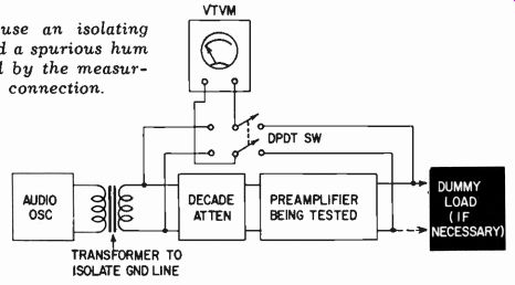
Fig. 615. How to use an isolating transformer to avoid a spurious hum problem,
introduced by the measuring equipment connection.
One disadvantage of this practice is that the same input may be needed for more than the one preamplifier. Perhaps a radio chassis can be provided with an outlet to a preamplifier input for playing over the hi-fi system and also with an alternative connection to another amplifier and speaker for use in another room, so the same radio tuner can be employed for delivering program material to alternative rooms. Under these circumstances a shorting switch would effectively kill the program in both places. Suit able isolation should be provided so the shorting switch does not short the actual input terminals but prevents leakage from this input into the signal path of the preamplifier.
Another form of cross-talk to check is in dual preamplifiers intended primarily for stereo use. Take the frequency response from one input to the other output when both are set for the same gain. Compare the gain and response of each channel with this cross-talk response. The cross-talk ratio may be given either as the ratio in db at 1,000 cycles or the minimum ratio at the worst point, in which case it is termed "minimum cross-talk" (Fig. 616).
Termination
Another thing to check in a preamplifier is the effect of different input, and output impedances. The preamplifier is usually designed to accept input from a variety of pickups or tuners as sources, but the effect of different input resistances on the frequency response and noise level of the preamplifier should be checked independently, to see how dependent its characteristics are upon such changes.
Similarly its output performance should be checked against changes of loading provided by the basic amplifier. If a preamplifier is provided with a cathode follower of nominal impedance in the region of 600 ohms, 'this does not necessarily mean it will operate satisfactorily into a basic amplifier with a 600-ohm input.
Usually this will result in considerably higher distortion.
A low-impedance cathode follower is intended to be operated into a high-impedance input of 50,000 ohms or higher at least.
The purpose of the low impedance is to avoid high-frequency losses due to shielded cable connectors, which occurs when the output of the preamplifier is at high impedance as well as the input to the basic amplifier.
The use of a 600-ohm load on a 600-ohm cathode-follower out put cause considerably more distortion, and also severely restricts the output voltage. A preamplifier that might give as much as 5 volts with a certain (low) amount of distortion before going into severe distortion when operating into a high impedance, may give less than 0.5 volt when operated into 600 ohms. Even at this voltage, the distortion will be considerably higher than the 5-volt output into high impedance. So this is something that should be measured in assessing the effect of output matching on the performance of the preamplifier.
In tube type preamplifiers, the input resistance or impedance is unlikely to affect the distortion produced by the preamplifier.
It will affect only the noise components, hum and hiss, to any appreciable degree. But in preamplifiers using transistors the input impedance connected to the preamplifier can affect distortion as well as hum and noise. Consequently, a transistor preamplifier should also be checked for the effect of input loading on other characteristics of the amplifier-its frequency response and distortion, as well as hum and noise.
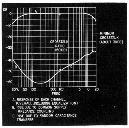
Fig. 616. Typical cross-talk curves.
Most transducers or sources that are fed into preamplifiers are voltage-producing devices. Consequently, it is important to check the effect of feeding from a low source resistance rather than a very high one. Crystal or capacitance transducers, however, can sometimes better be regarded as current type sources. For measuring the effect of impedance differences here it may be advantageous to check the effect of feeding the preamplifier from a very high source resistance, in the region of megohms, and then applying, as a supplementary source impedance, parallel capacitance to simulate the source impedance provided by the transducer.
With tube amplifiers these changes are likely to affect hum, noise and frequency response, but not distortion. But, with transistor preamplifiers, distortion also may be affected by such changes.
Microphony
In tube amplifiers microphony sometimes is encountered. This is a difficult thing to measure and give numbers to because the magnitude of output produced by the microphonic effect depends on how hard the tube is hit or the intensity of the vibration picked up by the chassis. Also, the microphony is of complex frequency construction because it sets up a complex vibration in the electrodes that produce it. The only thing that can be done is to investigate whether it is something inherent to the component used or just the particular sample that happens to be defective.
Supply changes
Preamplifiers must also be checked for the same kind of deviation that was discussed in the section on basic amplifiers, due to supply change or changes in signal level. Usually neither of these has such drastic effects on preamplifier performance as it can have on the basic amplifier. No preamplifier has such large amounts of overall feedback as do basic amplifiers.
Some preamplifiers in fact have no overall feedback loops at all.
Maybe individual stages utilize feedback to linearize them as individual stages, hence supply changes produce practically no effect whatever. Sometimes feedback may be used to produce tone compensation or equalization characteristics. Occasionally such circuits will produce a stability margin problem, but usually they are well enough designed to insure that no peaking occurs outside the range of frequencies for which the equalization is provided.
This being the case, the kinds of transient effects noted in basic amplifier performance do not usually arise in feedback preamplifiers. However it is well to check these things, especially in a pre amplifier where the schematic shows that feedback is employed to achieve tone-compensating or equalization characteristics.
Recommended Reading
1. W. B. Barnard, "Distortion in Voltage Amplifiers," Audio Engineering, February, 1953.
2. L. Fleming, "Distortion Measurements Without Tubes," Radio & Television News, March, 1951.
3. L. Fleming, "Voltage Amplifier Distortion," Radio & Television News, September, 1956.
4. Norman H. Crowhurst, "Why Loudness Control?" Radio & Tele vision News, April, 1957.
See also references at the end of Section 4, many of which are also applicable to this section .