It impossible to consider phono pickups (cartridges) and tonearms as separate entities from a performance point of view. This can be illustrated by considering the possible effect of arm resonance.
Resonance may be considered as a mode of vibration dependent upon the dimensions and structure of the arm itself. But whether this resonance has any effect on reproduction depends upon the degree of coupling between the pickup mechanism and the arm. This in turn is controlled by the reaction of the stylus to movement imposed on it by the record groove.
If the stylus produces zero reaction at all frequencies (that is, it moves infinitely easily), then the vibration transmitted from the record grooves will produce no vibration in the body of the pickup cartridge. This being the case, it cannot transmit any vibration to the arm, so any resonances in the structure of the arm are unimportant because the pickup mechanism will never excite them. All the arm is called upon to do, under these hypothetical circumstances, is to carry the pickup across the record so the stylus keeps pace with the spiral groove.
This is an impossible idealization. However compliant the pick up mechanism, it always produces some reaction at the stylus point and there is some tendency to transmit vibration from the stylus to the body of the pickup, which in turn is transmitted to the arm.
The amount of such transmission is relative and is determined by the characteristic of the pickup.
Consequently the effect of arm resonance upon the performance of the whole unit is dependent most upon the characteristics of the pickup. This does not alter the fact that it is desirable to eliminate arm resonances. It merely changes the relative importance of any that may be present.
Frequency response
Mechanical features usually cause pickups and arms to deviate from their ideal frequency response. If the pickup stylus could be rigidly coupled to the transducer mechanism and the body of the transducer mechanism be held equally rigid, then in most instances the electromechanical frequency response would be perfect.
A coil moving in a magnetic field is not in itself frequency-discriminative in the voltage output it produces. A certain rate of movement will always produce the same output voltage. Thus, a moving coil pickup is inherently a velocity pick-up device and its only electrical contribution to frequency response will be due to the resistance, inductance and self-capacitance of the coil itself.
The same is true of the magnetic construction. The output is due to the changing magnetic field which varies in conformity with the movement of the magnetic components controlling it.
Within the audio range, this is not appreciably frequency-discriminative. So the magnetic pickup also is basically a velocity device.
Crystal and ceramic pickups produce a voltage proportional to their deflection, provided they are operated open-circuit. The resistance into which they operate will tend to discharge this voltage according to a specific bass-loss characteristic that can be deter mined quite readily from the electrical characteristics of the unit.
But the basic transducer is a constant-amplitude transfer device without frequency discrimination in itself.
With each type of pickup, any frequency discrimination ob served, particularly the difficult, resonant types, are due to the mechanical properties of the coupling between the stylus and the transducer, including of course the stiffness of the crystal or ceramic itself.

Fig. 701. The position taken by the stylus at any instant depends on both
disc and pickup compliances.
The most convenient means for taking frequency response, measuring sensitivity and other characteristics of a pickup, uses one of the wide range of test records available on the market. They contain calibrated test frequencies and also standard velocity magnitudes for determining sensitivity.
However, tests with a variety of these discs may produce apparently conflicting results. Fortunately, it is simple to check the frequency response recorded onto the disc by the light-calibration method described earlier. This utilizes the fact that the width of a light reflection pattern is dependent upon the maximum velocity of the groove. This makes it relatively easy to construct a test record of known calibration, and there are quite a number of good records of this type on the market. Unfortunately, this is not quite the whole story....
The complete performance of the pickup includes the performance of the stylus in the groove itself. If the record were completely rigid, so the stylus riding in the groove had to move in conformity with the modulation in the groove, there would be no reason for discrepancy between one test record and another, provided the maximum signal-handling capacity of the pickup is not exceeded at any point.
But with practical discs, which are not infinitely rigid, the stylus movement is determined by the ratio of two compliances: the compliance of the groove walls pushing it, and that of the pickup tending to stop it from moving (Fig. 701). If the compliance measured at the stylus point due to both these causes is equal, then the output from the pickup will be reduced 6 db as compared with the same grooves driving the pickup, but with completely rigid grooves.
In modern pickups, the stylus compliance is invariably much greater than that of any disc material. But it is evident that the figures obtained from different test discs, both as to frequency response and sensitivity of the pickup, may disagree due to difference in the compliance of the pickup compared to the disc.
To obtain standards in this regard it is necessary to establish more accurately the stylus movement itself. For this purpose the stylus is driven, not by a record groove, but some other type of transducer, possibly a moving coil from a speaker, coupled mechanically to the stylus point. The important thing is to establish the magnitude of movement of the stylus point and from this deduce the transfer characteristic of the complete pickup.
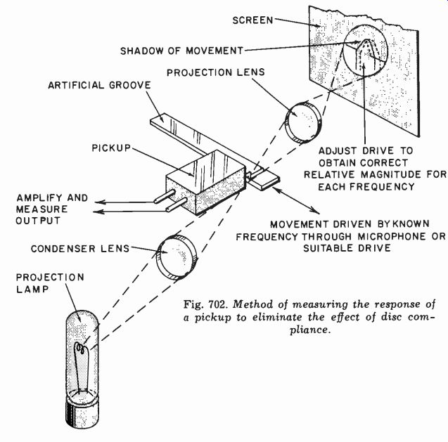
Fig. 702. Method of measuring the response of a pickup to eliminate the effect
of disc compliance.
The simplest way of establishing the magnitude of stylus movement is to use a projection microscope and throw the shadow of the stylus complete with its movement on a screen. Then with known optical magnification the magnitude of movement can be accurately measured and adjusted by the driving force to a specified value. In this way, a frequency response of the pickup can be taken independently of the effect of record material (Fig. 702).
Technically, this may be regarded as the response that should be published for the pickup. But of course it has no practical value because pickups do not play in grooves with infinitely rigid walls. Consequently a response measured with a practical test disc is more acceptable-if less definite as to its meaning.
One advantage of driving the pickup mechanically so the stylus movement can be controlled is that it eliminates one variable from the measurement and thus enables more ready evaluation of the contribution of different components of the pickup performance.
As far as the pickup mechanism is concerned, two factors, broadly speaking, contribute to the frequency response: the mechanical reactance 'seen' at the stylus point and the effectiveness of coupling between the stylus point and the transducer element.
Some pickups, such as the G-E for example, concentrate on get ting the transducer as close as possible to the stylus point. This then means the output voltage is determined almost entirely by the relative movement between the stylus and its cartridge. In other words, this almost eliminates the second possible cause of frequency discrimination. However, close coupling in this way does not eliminate the first possible cause-the fact that the stylus presents a mechanical impedance to the stylus point, and consequently may require considerably harder driving at some frequencies than others.
Technically such a pickup will produce the best frequency response when measured by driving the stylus mechanically and holding the cartridge rigidly. But by the same token this kind of pickup can show a greater deviation in performance when test records are used instead of such a mechanical drive. It does not necessarily mean that this type of pickup will also show greater variation in frequency response according to whose test record you happen to use.
The other trend in construction uses a mechanical coupling between the stylus point and the transducer element. Moving coils employ such a construction because a leverage is required between the stylus point and the coil, which is located in a magnetic gap. Various types of construction are used, each of which has its own mechanical resonances.
A mechanical resonance in the stylus arm coupling the stylus itself to the coil can result in excessive movement of the coil compared to the drive motion at the stylus. This will produce a large resonant peak in the output response, which will occur with equal force whether driven by a relatively compliant disc or by an almost rigid one. But the magnitude and frequency of the peak, particularly the latter, may be shifted by using a disc of different compliance.
We could pursue this discussion through the relative types of pickup construction. Some of the ceramics use quite a complicated lever system to transfer the stylus movement to the "distorting element" in the crystal that produces an output voltage. To design the resonances out of his system as far as possible is the pickup manufacturer's job. What we are concerned with here is measuring the performance. The only reason for going thus far into the mechanical aspect is that it is very helpful in visualizing what can be causing certain resonances when interpreting the results measured.
The arm usually produces a sequence of resonances toward the low-frequency end of the audio range. This can be checked independently, if desired, in designing the arm, by driving at the point where the pickup is inserted mechanically and measuring the motion produced at different points along the arm. Alternatively, the mechanical driving-point impedance can be measured as a frequency response.
The latter method is probably the most satisfactory because it determines what mechanical reaction the arm presents to the cartridge mounting. The best approach is to use a strain-gauge crystal in the drive coupling, so the drive force applied to the application point can be measured while using the shadowgraph method of determining the magnitude of movement induced (Fig. 703). A plot of these relative magnitudes will give the mechanical impedance characteristic of the arm measured at this point.
This impedance should be a rising one, characterized by less movement (with a constant drive force) with increasing frequency.
The thing to watch for is any dips in impedance due to resonances that would allow the arm to pick up more motion than it should from the drive to the pickup stylus.
These measurements are said to be most important in the lateral plane. But spurious vertical effects can also interfere with lateral performance due to mechanical translation effects. With the ad vent of stereo discs, measurement in both planes becomes even more vital.
The vertical mechanical impedance characteristic can be measured in just the same way as the horizontal, by applying the force vertically and measuring the movement by a shadowgraph.
Sensitivity
This is measured by driving the pickup at known amplitude and measuring its electrical output with a calibrated amplifier. Frequency is important, as sensitivity is usually expressed in terms of output volts per unit velocity of drive. Magnitude of movement is connected with velocity on a 6-db-per-octave basis.
Assume the peak-to-peak movement amplitude is 2A, as measured by the shadowgraph. This means the movement is given by:
S = A X sin wt = A x sin 2rft
where f is frequency in cycles. Then velocity will be:
ds
= 2rAf X cos 2irft dt
When we speak of stylus velocity, we mean the maximum instantaneous velocity which will be 2rAf.
To take an example, assume the peak-to-peak movement is .01 cm at 1,000 cycles. Then A is .005 cm, and velocity is 2r X .005 X 1,000 = 31.42 cm/sec. The same magnitude of movement at twice the frequency would be twice the velocity, and should, in a velocity type pickup, produce twice the output voltage.
Impedance
Pickup impedance can be measured by normal bridge methods and the electrical impedance of a pickup indicates quite accurately how the termination at the input to the preamplifier can modify the frequency response of the pickup.
If the pickup contains inductance, as most moving-coil and magnetic types invariably do, then terminating the pickup with a lower value of resistance will result in a high-frequency turnover at lower frequency.
If the pickup is of relatively low impedance (less than, say, 5,000 ohms), then its own capacitance is not likely to bother it as regards frequency response. But the capacitance of a connecting cable can always cause high-frequency loss, unless the impedance of the pickup is kept to a low enough figure to avoid this. All of these effects can be computed on simple frequency-response parameters of the circuit elements involved.
In ceramic and crystal pickups the source impedance of the pick up is approximately that of a capacitor. Consequently, termination in different values of resistance will result in different degrees of bass loss. The pickup is regarded as a constant-amplitude rather than a constant-velocity device as are moving-coil and magnetic types.
Compliance and dynamic mass
Pickup compliance is not a very easy thing to measure, largely because of the very minute size of the components. It is impossible to connect an additional compliance to the stylus point, either in the form of the disc that drives it or a compliant driving source such as a rubber pad, without also adding to the stylus point mass as well as compliance.
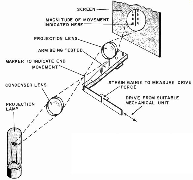
Fig. 703. Setup for checking the mechanical impedance characteristic of the
arm.
Static compliance is measured fairly simply by applying a small force and noting the movement it produces. But dynamic compliance is complicated by the various other factors involved.
It can be measured by comparative means, using a driving source of known compliance and determining how much the movement of the stylus is reduced, by allowing it to be driven by a compliant source as compared with a rigid one. The change in magnitude of movement then, gives the relative compliance of the driving source and of the pickup movement itself. However, this has to be interpolated on the basis of measurement over a range of frequencies, so the contributing masses can also be calculated as well as the compliances.
Dynamic mass or inertia of a solid moving part, such as a stylus arm, can usually be calculated reliably from the mechanical formula for the mode of movement used. An alternative approach in discovering compliance, at least in the region of the resonant frequency of the device, is to check by means of a strobe whether the mode of movement remains according to theory as the driving frequency is passed through resonance. Then the frequency characteristic can be taken and analyzed from the known value of mass and other circuit elements to provide a characteristic for the compliance value.
Completely detailed calculations of compliance values are be yond the scope of this guide and the reader is referred to the further reading at the end. of the section for appropriate literature.
However, it will soon he important (more so than heretofore) to measure the vertical as well as the horizontal compliance, as this will determine the compatibility of an LP pickup for playing stereophonic discs without ruining the grooves for playing by a stereo pickup. This is more important than has sometimes been realized even for playing lateral recordings. Lack of adequate vertical compliance increases the susceptibility of the pickup to spurious effects, including some varieties of intermodulation, due to vertical vibration modes in the mechanical system.
Measuring the characteristics of stereo pickups involves measurement of dynamic mass (inertia) as well as the compliance in both directions. It also involves measuring the frequency response and sensitivity of the pickup to motion in both directions.
For single-channel pickups a variety of combinations of vertical and lateral characteristics can be used and the choice varies considerably. Some have almost zero vertical compliance while some have a compliance almost equal to the lateral. The mass required in both directions varies with different hypotheses too.
A relatively high dynamic arm mass laterally is usually employed to minimize vibration transfer from the stylus due to the stylus compliance. Vertically, however, the pickup has to track the warp age on a bent record without any tendency to leave the groove when it gets to the top of its excursion. This is usually achieved by minimizing the vertical dynamic mass so the pickup follows the groove down again.
If a larger tracking force is used, equal to the actual mass of the pickup for example, there is no problem. But modern pickups have been working toward smaller tracking forces. For some time it seemed as if 5 or 6 grams was about the minimum. But several pickups now available utilize a tracking force in the region of 1 or 2 grams. This means the dynamic mass in a vertical direction must be correspondingly smaller, otherwise the pickup will be left in the air because of a sudden vertical undulation due to warpage.
Smaller tracking forces which can be measured with some kind of balance (see Fig. 704) mean that all the corresponding masses can be reduced in the same proportion. This not only reduces record wear but makes it simpler to achieve wide-range frequency response with good precision.
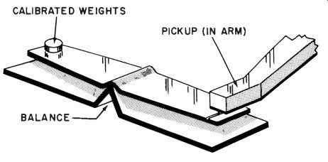
Fig. 704. A simple stylus balance for measuring stylus force.
While reduction of vertical tracking force reduces wear on the bottom of the record groove, making it too light will cause the stylus to ride up the groove wall, producing distortion and also damaging the wall. This wall-riding tendency would be stimulated by lateral velocity at frequencies where lateral stylus motion is compliance-controlled. These are usually the low frequencies, where velocity is low; but where the stylus motion is mass-controlled the riding tendency is acceleration stimulated.
This means the safe-handling signal magnitude, set by the stylus tracking force, is inversely proportional to frequency at the high end, on a velocity basis, or to the square of frequency on an amplitude basis. An alternative thing that happens at these high frequencies is that the record compliance absorbs, the "motion," losing these frequencies from the reproduction. This action may also "clean off" these frequencies from the disc, especially by repeated playing.
Distortion
As well as the effect on frequency response of the pickup acting as a transducer, we need to consider possible forms of distortion that a pickup can produce. If a harmonic method of measurement is used, the term of distortion involved is relatively less important than if an IM method is employed.
To measure the distortion of a pickup it is necessary to drive the stylus mechanically, usually by very carefully prepared records, and then measure the distortion present in its output. The fact that the input to a pickup is a mechanical one precludes the input/ output comparator method that has been suggested for amplifiers and preamplifiers. We have to be content with making the mechanical input as pure as possible and then measuring the distortion components in the output.
The same variety of IM distortion signals can be used for testing pickups as for other items of equipment, either the low- and high-frequency or the beat-tone combination. With any measurement in which the input signals are removed from the output and the residue measured as a distortion component, some precaution, such as checking on an unmodulated groove, is necessary to insure the quantity measured is not due to rumble or hum.
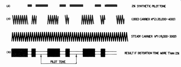
Fig. 705. Operation of the A-N IM test for a pickup-playback system.
The beat-tone combination in a form of disc that gives an A-N indication that can be heard has been very popular, largely because no additional test equipment is necessary. The disc can be put on a turntable and the pickup played on it. Careful listening to the beat tone to determine whether the Morse code A or N is heard establishes whether the distortion is above or below limits (Fig. 705).
The disadvantage of this method is that the only distortion it indicates is that due to asymmetrical nonlinearity in the mechanical-to-electrical transfer characteristic of the pickup. If the pickup is out of alignment (in the case of a magnetic type nearer to one pole piece than the other, for example), then there will be a very definite asymmetrical nonlinearity. Sometimes nonlinearity is due to the side force produced by the drag component of friction relative to the disc. It is true a variety of possible asymmetrical non linearities is inherent in pickups as distinct from other audio de vices. But this does not alter the fact that damping material and other components of the pickup may well cause symmetrical non-linearity, which this particular type of distortion measurement does not detect.
For this reason either the harmonic method of measurement or an IM method employing the low- and high-frequency tones is preferable as it detects both forms of nonlinearity.
One cause of asymmetrical nonlinearity is that contributed by arm tracking. At certain points the stylus movement is not perpendicular to the direction of groove travel. By using correct offset angles and operating the arm within the range for which the offset is designed, this kind of distortion can be kept within known minimum values.
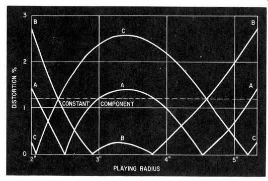
Fig. 706. How so-called tracking distortion due to arm mounting (offset angle
and overhang) can be invalidated by other distortions. Here the dashed line
represents a constant distortion due to other factors. Curve A is the ideal
curve for tracking distortion. A combination of the two produces curve B or
C, according to the phase relationship. By altering the arm mount so tracking
distortion would theoretically come out to curve B or C, the result can be
modified to curve A.
Most presentations on the subject assume that this kind of distortion is the principal one and analyze it as a separate entity. If, however, this asymmetrical nonlinear distortion should combine with another residual asymmetrical nonlinear distortion inherent in the pickup itself or due to record drag, then some degree of cancellation may occur with one phasing of the tracking distortion, while addition will occur at points on the disc where the phasing of tracking distortion is reversed (Fig. 706) . This may well mean that the ideal offset angle and degree of overhang for one pickup may differ from that for another because of the tendency of the tracking distortion to interact with other forms of distortion which are also asymmetrical in nature.
This is a region where an A-N test (which detects asymmetrical forms of distortion specifically with the test signal inscribed over the entire range of radii to be used) can be helpful in determining the best tracking condition for this particular compromise.
Utilization features
Finally, in testing pickups and arms we come to some factors that do not lend themselves to specific measurements, but which require assessment as to their practical performance value. One of these is the possible danger to records from wear or accidental damage.
One would presume wear to be proportional according to some relationship to the stylus tracking force used. A 6-gram pickup will produce six times more wear than a 1-gram pickup, or it may follow some other relationship. But this is not the only factor that controls the degree of wear. Increased vertical force on the stylus, if it causes the stylus contour only to rest more firmly on the bottom of the groove, will necessarily increase wear on the groove bottom. But, if insufficient stylus force is used and the diamond does not rest at the bottom of the groove at all times but rides up a little and bounces around, this can result in increased wear for reduced tracking force. This can usually be indicated at the same time by distortion measurements because, when the stylus rides up the groove, considerable distortion will be present. But there are other factors that contribute to the wear imposed on the disc.
Among these is the compliance of the stylus, which is a measure of how readily it follows the undulations recorded in the disc. A stiffer pickup will naturally tend to wear the walls of the disc more than one that is more compliant. Further than this, possible frequency-discriminative reactions to stylus movement, due to resonances and other features of the stylus arm assembly, may also contribute to frequency-discriminative wear that may tend to score out particularly high frequencies, for example.
Reactions of this nature will usually be accompanied by two other effects. If considerable force is transmitted back to the stylus point due to a resonant effect, it will also produce a strong force at the other end of the stylus movement, causing considerable force to be applied to the cartridge body. This in turn means, when the electrical reproduction is turned off, that increased needle talk will be noticeable due to radiation of this particular sound component from the vibrating cartridge body. Then, whether or not the cartridge body vibrates, increased force on the disc surface may also increase effective needle talk due to the actual vibration induced in the groove walls.
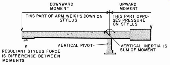
Fig. 707. Mechanics of a mass- (or weight-) counterbalanced arm.

Fig. 708. Mechanics of a spring-counterbalanced arm.
So it is a fairly safe generalization to say that the relative wear prospect of a pickup can be approximately estimated by listening to the relative needle talk with the amplification turned off. This is something that cannot be given a figure, but can readily be listened to, comparing one pickup with another.
Another thing that can happen with a phono assembly is due to vibration picked up from other sources. This may cause the pickup arm mounting board to transmit vibration, vertically or in other directions, that ultimately reaches the stylus point. Such vibration can be transcribed in this way as a spurious pickup effect, making the whole assembly sensitive to floor vibrations and producing a form of microphony. This can be prevented to some extent by absorbent mounting and mechanical filtering.
But vertical components of this kind of force may produce a resonant effect causing the stylus to jump out of the groove or to be uncertainly pressured into the groove, resulting in distortion and additional wear. With the modern extremely low tracking forces, it would seem to be ideal to have a pickup and arm assembly which is dynamically balanced so that external vibrational forces produce no resultant output of this kind.
Some arms use gravity to provide the necessary tracking force, using a mass differential fore and aft of the vertical pivot, so the stylus force is precisely the required value (Fig. 707). Others use a spring counterbalance for the gravity vertical component, thus avoiding the necessity for a large counterpoise weight, which does have the effect of increasing the vertical component of dynamic mass (Fig. 708).
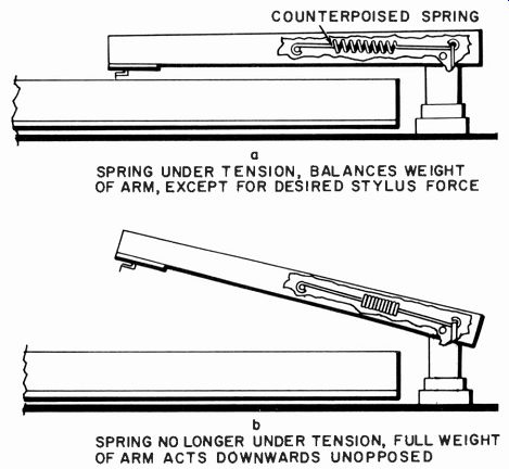
Fig. 709. A disadvantage of some spring-counterbalanced arms is the greater
downward acceleration from a small distance above the disc. This disadvantage
can also appear in certain designs of mass counterbalancing.
Whichever method is employed, a feature that can be of importance in possible accidental damage due to careless lowering of the stylus onto the disc is the way in which the stylus force changes with height of the stylus above the record. With a carefully counterbalanced gravity scheme, using fairly long arms, the stylus force does not vary appreciably over a height even of several inches.
But, with the spring counterbalance method and some forms of gravity methods, there can be a more rapid change. A force of 1 gram at the surface of the disc may be increased to 10 grams from 1/2 to 1 inch above the disc (Fig. 709). This is dangerous because it means that the dynamic mass is accelerated toward the disc with a force of the order of 10 grams, although the acceleration force when it reaches the disc is only 1 gram. The cumulative effect on the dynamic mass can produce destructive impact of the diamond into the groove.
One does not normally lower a stylus this carelessly, but the fact that such a design makes it subject to accident in this way is a detrimental performance factor, especially if the instrument is to be used by nonprofessional people unskilled in the application of stylus to record. Alternatively, too great a vertical dynamic mass can produce similar results, as well as being detrimental to operation on warped records.
We cannot close this section without reference to viscous damping in arms. As with other features, it must be related to pickup performance, particularly the stylus compliance. While one can generalize, the only real answer to the problem is in overall performance tests, as outlined in this section , for the individual arm-pickup combination.
Recommended Reading
1. Norman Pickering, "Effect of Load Impedance on Magnetic Pick up Response," Audio Engineering, March, 1953.
2. J. G. Woodward and J. B. Halter, "The Lateral Mechanical Impedance of Phonograph Pickups," Audio Engineering, June and July, 1953.
3. W. A. Fitzmaurice and W. Joseph, "Pickup Loading and Its Effect on Frequency Response," Audio, July, 1954.
4. John M. Salani, "Evaluation of High-Fidelity Pickups," Audio, March, 1955.
5. F. V. Hunt and D. A. Barlow, "On Stylus Wear and Surface Noise in Phonograph Playback Systems," Journal of the Audio Engineering Society, January, 1955; July, 1956.
6. John D. Seagrave, "Minimizing Pickup Tracking Error," Audio craft, December, 1956; January and August, 1957.
7. Joseph Marshall, "Loading Phono Pickups," RADIO-ELECTRONICS Magazine, October, 1956.
8. Norman H. Crowhurst, "Buying a Tone Arm," Radio & Television News, January, 1957.
9. Bent Gehlsh0j, "Electromechanical and Electroacoustical Analogies," Akademiet for de Tekniske Videnskaber, Copenhagen, 1947.
10. Harry F. Olson, Acoustical Engineering, D. Van Nostrand Co., New York, 1957.