[… Missing content …] move at constant speed, but also the points where the tape passes the record and playback heads (Fig. 901). These, after all, are the important points where the tape has to perform correctly.

Because all magnetic recording tape is an elastic material, its motion must be completely smooth. If any of the guide posts used to direct it around its transport parts cause the tape to shudder, even though the tape drive at the capstan is perfectly constant in its speed, this varying tension will be reflected at the point where the tape passes the playback and record heads.
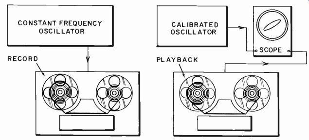
Fig. 902. A method of checking for overall relative speed constancy as well
as flutter and wow.
Flutter and wow
Measurement of speed constancy is relatively simple, following the same method employed for turntables and record changers.
A flutter and wow meter is used to determine all kinds of speed fluctuation. First, the constant frequency has to be applied to the tape and then it has to be played back and measured (Fig. 902).
To achieve perfect constancy of the played-back tone, complete freedom from flutter or wow in both the recording and playback process is necessary.
The degree of flutter and wow induced by the transport of the tape may differ on record or playback either because the tape heads occupy a different position along with tape motion, or the mechanisms are slightly different (applying different pressure or tension in some way). In most instances the degree of flutter or wow produced both in recording and playback will be of the same order.
Consequently, an advantage in measuring flutter and wow on a tape recorder by using a constant-frequency oscillator to record and then playing the same tapes back is that it doubles the sensitivity of the measuring apparatus.
There is the possibility that flutter and wow components are out of phase, so the resultant output becomes almost constant.
Usually there is some deviation so that, at other points along the tape, the two components of flutter and wow get into the opposite phase relationship and so there is twice as much frequency deviation due to flutter and wow results (Fig. 903) .
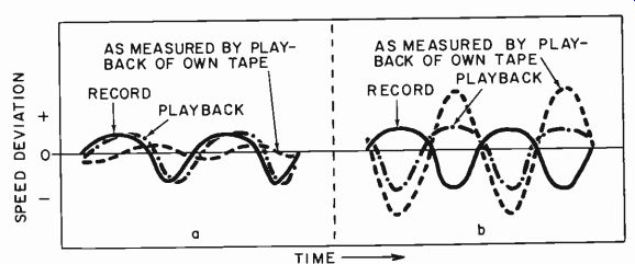
Fig. 903. How an overall relative flutter or wow test (Fig. 902) can vary
according to a time relationship, although the actual deviation on both record
and playback may be the same.
Constancy of speed needs checking throughout the entire length of the spool of tape that the machine handles. The tension applied by the takeup motor varies from the beginning to the end of the tape. At the beginning a given torque produces more tension on the tape than at the end because the spool is operating at a much larger radius. Consequently, the takeup tension can alter the speed throughout the run of the tape.
This really calls for a calibrated tape since in using a constant frequency to record and play back with the same recorder, any error in speed is likely to repeat in playback. For example, if the nominal speed is 7 1/2 inches per second, the spool may start operating at 7 ¾- inches per second and finish in the region of 7 1/4.
If this operation occurs or repeats identically on record and play back, the constant frequency used to record from beginning to end will be reproduced precisely on playback.
If there is a slight difference between record and playback speeds (for example, the beginning playback speed may drop from 7 3/4 to 7 5/8 ips while the end will drop from 7 1/4 to 7 1/8), this results in an approximately uniform drop in frequency on playback and no indication is given that the speed varies throughout the duration of the tape. It just seems as though the playback is slower than the record.
For this reason we need a calibrated tape with the frequency recorded on it at a calibrated speed. This can be achieved by using a tachometer (see Fig. 904)-a precision instrument that indicates exactly the speed at which the tape passes. By using a tape recorder that provides for speed adjustment a specified frequency can be recorded on the tape for use in testing the speed constancy of tape recorders.
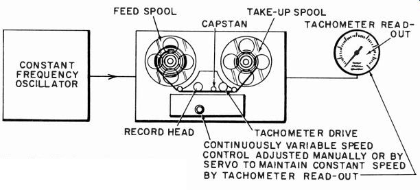
Fig. 904. Method of preparing a standard tape for a speed constancy test.
Performance on record can be deduced, either by comparison of self-recorded tape with pre-calibrated, or by analyzing the recording made on the tape with the machine under test (Fig. 905).
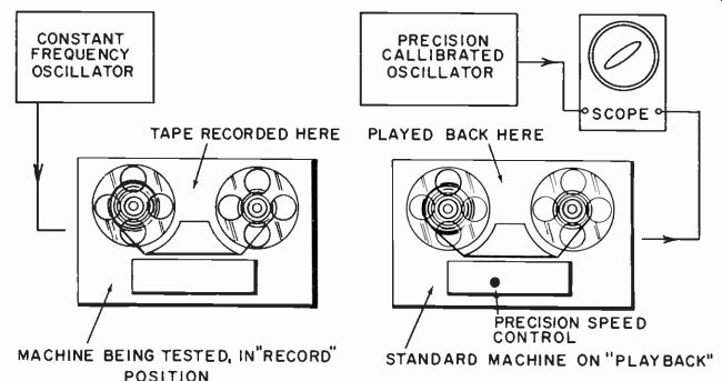
Fig. 905. Method of testing the record speed constancy of a machine (left)
against a precision standard (right).
Tape handling
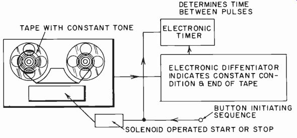
Fig. 906. Setup for measuring start and stop times electronically.
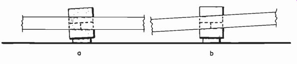
Fig. 907. Incorrect alignment can be due to error in the head mounting (a),
or in the tape transport past the head (b).
A mechanical utility feature of a tape recorder is the speed at which it can start and stop the tape, both from normal playing speed and also from the fast forward and rewind speeds. Tape, unfortunately, is not as convenient to handle in this respect as disc, where all that is needed to pick off a particular piece of pro gram is to lower the stylus to the desired groove. In tape, finding a desired position in a 1,200-foot (or more) length of tape re quires fast forward or rewind until the desired position is located.
This requires good acceleration on the motors that provide the fast forward and rewind action and also careful but rapid braking to stop the tape very quickly without breaking it. This information is usually given as the time taken to start or stop from each running speed, which can readily be measured with a stopwatch and calibrated tape (Fig. 906) .
The tape transport mechanism is also responsible for that very important aspect in tape recorder performance, maintaining correct tape alignment. The normal alignment of a tape uses a magnetic gap which runs transversely across the tape to produce a longitudinal magnetization. The angle of the gap should be at precisely 90° to the direction of tape motion.
Maintaining this precise 90° angle is important to the reproduction of the very high frequencies whose wavelength is comparable with the magnetic length of the playback head. Consequently, precise alignment is necessary to high-quality reproduction. This requires not only insuring that the playback head does not move in any way with the operation of the recorder so as to change this alignment, but also that the transport mechanism guiding the tape past the head does not allow it to change its angle of transit at this position (Fig. 907). This means the tape must cross the guide posts in such a way that it cannot slide to and fro and change the angle of transit past the heads.
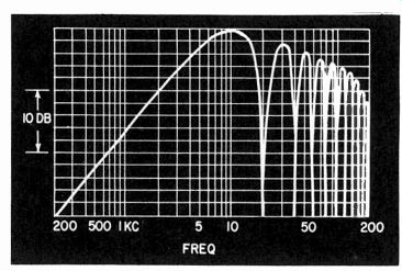
Fig. 908. Response of a very good head, showing successive nulls that indicate
the effective gap length.
The basic method of checking alignment is by precision measurement of the head angle and parallelism of tape transport. This establishes a standard. Then for routine checking, which is used practically all the time, a tape recorded with high frequency-the higher the better-at precision alignment is played on the machine being tested, and adjustments made to produce maximum high frequency output. For rough alignment, a frequency as low as 5,000 cycles is sufficient, since the output will be obtained even if the head is several degrees off and it will be possible to see "which way to go" to correct it. For fine alignment, a high frequency is used, which may be 7,500 or 10,000 cycles (or even higher) depending on the tape speed and the head response anticipated.
The important physical properties of heads are in the gap that comes in contact with the tape. A microscope is used for physical examination and appropriate analysis of frequency responses made with the heads.
For a playback head, the gap needs to be very narrow, parallel, straight and at 90° to the tape motion. When a good-quality gap is so aligned, its magnetic width is measured by the location of nulls which occur at wavelength intervals (Fig. 908). A poor gap will show up by not producing definitive null points in the response.
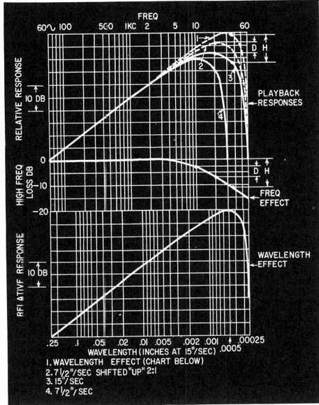
Fig. 909. Playing tapes with different frequencies re corded, at different
speeds, can be used to separate frequency and wavelength effects. The dimensioned
points 'D' show how the frequency effect is isolated from the two solid curves
by construction; dimensions 'H' show how wavelength effect is then found from
15"/sec. curve and frequency effect, re-plotted below to a wavelength
scale (which then becomes applicable to any speed).
Effects due to gap width can be separated from other frequency-discriminative effects by varying the tape speed. While wavelength is dependent on both frequency and tape speed, once a frequency is recorded on tape its wavelength does not change: frequency and speed change together. Thus a combination of different frequencies, recorded with the tape played at different speeds, shows two kinds of variation, according to whether the effect is due to frequency or to wavelength (Fig. 909).
For a record head, the trailing edge of the gap is most important (Fig. 910). It is not important for the gap to be very narrow, because the bias frequency is cyclically magnetizing the tap at a frequency whose wavelength is a small fraction of the gap length anyway, so that a number of cycles of bias magnetization occur while the tape passes the gap, even when it is as narrow as possible.
With a wider gap, a greater number of cycles occur during this transit. What is important is the way the bias magnetization is tapered off and this is determined by the trailing edge of the gap.
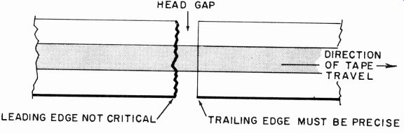
Fig. 910. The trailing edge of a record head gap is the important feature.
(In combination record/playback heads, limitations are set by playback requirements.)
Frequency response
Measuring the overall frequency response, distortion and dynamic range characteristics of the tape recorder is very similar to the corresponding operation on a disc recorder. The big difference is that tape has a precisely restricted dynamic range, limited in one direction by the maximum magnetization the tape can receive without running into distortion and in the other direction by the inherent noise of the system.
Maximum magnetization on the tape is limited by the onset of saturation. At a certain magnetic density the recorded distortion, as measured on playback, makes a rapid increase (Fig. 911). This will occur at approximately the same record current, regardless of frequency. (The only thing that invalidates this relationship is the record-head loss, which is quite small over most of the range in a well designed head).
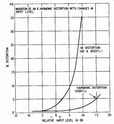
Fig. 911. Distortion characteristic for a typical tape, measured by the two
most-used methods.
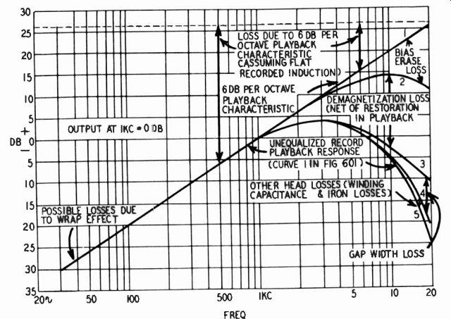
Fig. 912. An analysis of typical playback losses in a tape and playback head
at a speed of 7.5"/sec.
The impedance of a head is basically inductive; a constant current at varying frequency is accompanied by a voltage proportional to frequency. Correspondingly, the output from a playback head is proportional to the rate of change of magnetization. If the tape is magnetized to the same density at all frequencies, the playback head produces an output that rises at 6-db-per-octave with frequency. In practice, the response is modified by various losses to a typical curve shown in Fig. 912.
Thus, assuming the maximum anticipated signal is the same electrical voltage at all frequencies, this should be converted to constant current in the record operation and requires a 6-db-per octave boost on playback.
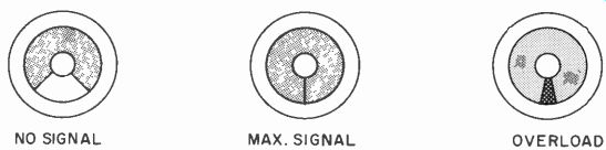
Fig. 913. The type of indication given by a "magic-eye" level indicator.
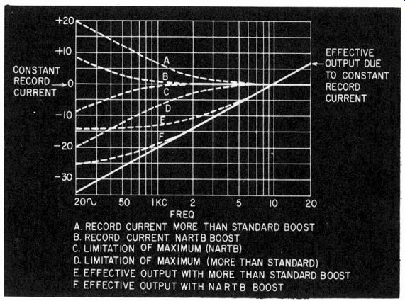
Fig. 914. Deviation from the ideal "constant current record" condition,
by using bass boost, results in limitation of maximum density, but allows
a larger relative output on playback at low frequency. Two deviations from
the ideal are shown, the NARTB standard, and a much-increased boost.
This means the chosen equalization characteristic must be closely adhered to, and also the record level must be carefully monitored to see that useful "headroom" is not wasted so as to reduce the effective dynamic range of the tape. For this reason, even the cheaper home tape recorders are provided with level indicators, usually in the form of a peak-reading device such as a neon lamp or a "magic-eye" cathode-ray tube which will indicate precisely when the maximum permissible level is reached (Fig. 913). Professional machines usually employ the regular VU type meter, which is a mean-reading indicator. While this is not so precise, most people associated with the recording and broadcasting industries have become so used to its characteristics that they understand what they are doing with it better than they would with a peak-indicating device.
Consequently, they are able to operate at a reading below the maximum saturation level, according to the program content being recorded. This allows a satisfactory margin. It is a matter of experience and one which a skilled operator can achieve quite successfully. For the unskilled operator, the peak-reading type of indication is much more useful because it indicates to him exactly when a permissible degree of magnetization is reached.
The equalization of tape recording must take into account a velocity compensation very similar to that encountered in disc recording. The important relationships in tape recording are based upon a basic linear relationship between record current and magnetization and, on playback, the relationship is at 6 db per octave due to a velocity effect. The output voltage is proportional to the rate of change of magnetization.
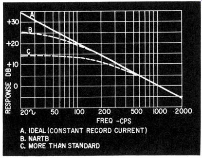
Fig. 915. The deviations of Fig. 914 allow a turnover to be used in the playback
equalization.
Consequently, somewhere in the overall equalization characteristic, there has to be introduced a 6-db-per-octave slope virtually from one end of the frequency range to the other. If in record a constant-current basis were used for the whole frequency range, this would require 6-db-per-octave boost on playback for the whole range, with a consequent very high gain for the lowest frequencies. The alternative is to provide some low-frequency boost on record, with a consequent reduction of maximum signal that can be accepted in this range (Fig. 914) . This permits a turn over to be used on playback (Fig. 915).
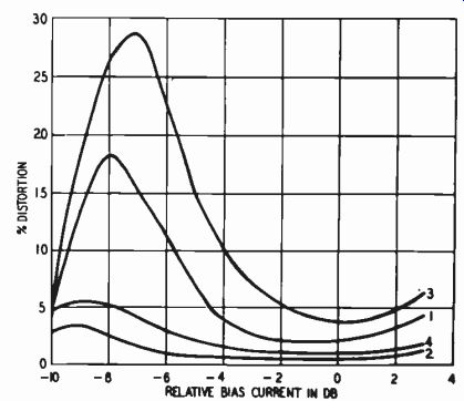
Fig. 916. Variation of IM and harmonic distortion with changes in bias current.
Curve 1: IM distortion at a playback level corresponding to + 3 on the VU meter.
Curve 2: IM distortion at playback level corresponding to 0 on the VU meter.
Curve 3: Harmonic distortion at a playback level corresponding to + 3 on the
VU meter. Curve 4: Harmonic distortion at playback level corresponding to 0
on the VU meter. (Source: Audio, October, 1956.)
On playback a 6-db-per-octave falling characteristic is required to convert the constant current (which is a constant-magnetization density) into a constant-voltage output. At a certain frequency how-ever, usually between 1,000 and 2,000 cycles, there is a turnover point due to the playback characteristics of the head and various other losses. Eventually a null is reached because both edges of the head occupy a similar point of magnetization and there is no magnetic "difference" to play. This is illustrated in Fig. 912. To compensate for this the 6-db-per-octave downward slope is leveled off and a high-frequency boost is inserted to produce the required overall frequency response.
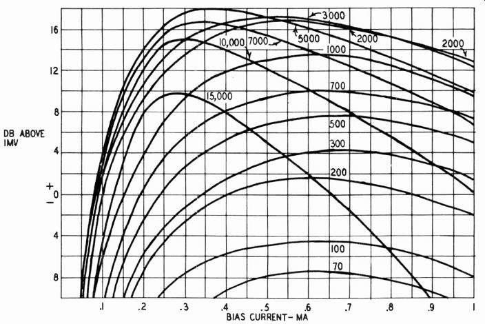
Fig.
917. Variation of output with bias current at various frequencies. Data are
far a Brush BK-1090 head, operated at 7.5 ips. (Source: Otto Kornei, "Structure
and performance of Magnetic Transducer Heads," Journal of the Audio Engineering
Society, July, 1953.)
Fig. 918. Method for connecting a bias current meter in series with bias current feed to the record head.
High-frequency bias
This introduces another important factor in the performance of magnetic tape-the high-frequency bias. It minimizes nonlinear distortion due to 'the magnetic material on the tape. Lack of high frequency bias produces excessive distortion. Fig. 916 shows a typical characteristic. Unfortunately, however, excessive high-frequency bias also tends to swamp the high-frequency response.
This depends on the tape characteristics, the bias frequency and the record head gap. Fig. 917 shows typical results.
The record-head gap width is greater than the equivalent wave length of the high-frequency bias, consequently only a small residual bias appears upon the tape. What the high-frequency bias does is to virtually "demagnetize" the tape to a "static" value of magnetization corresponding with the instantaneous audio signal. But there still is a residue of high-frequency bias and, if the tape is played back slowly enough, it becomes audible. Loss of the high frequencies by use of excessive bias seems to be associated with some kind of swamping effect that occurs due to the residual recorded bias when too much is used.
Whatever the exact explanation of this deterioration in high-frequency response with excessive bias may be, the result from a practical viewpoint is that high-frequency bias needs to be care fully controlled to achieve minimum distortion with minimum loss of high-frequency response. The effective high-frequency bias is dependent upon the current passed through the record coil. Consequently, where adjustment is made to measure according to a meter, the meter is arranged to measure the high-frequency bias current (Fig. 918).
However, the correct adjustment for one type of tape may be an incorrect adjustment for another. Usually a recorder is adjusted to some nominal value which achieves best average results with the types of tape commonly used. If optimum results are required with all types of tape, some experimentation is necessary to determine the optimum high-frequency bias for each tape used, and also the maximum density or audio record current that can be used.
These can be noted as meter readings and any time the tape is changed the recorder can have its bias reset to suit this particular type tape and the maximum level adjusted accordingly. This is one advantage of using a meter, rather than the simple indicator. A refinement for the indicator is to make it adjustable, with calibration (Fig. 919).
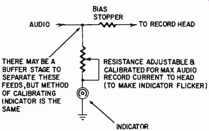
Fig. 919. Making the record level indicator adjustable to suit the maximum
density levels of different tapes.
Getting down to details of the response characteristics of record and playback heads is much easier in a tape recorder than it is in a record player. The only contributing factors to frequency response are those related to the physical dimensions of the head and the gap effect between the magnetization on the tape and the air-gap width of the head. Also, the electrical characteristics can readily be measured: the inductance, resistance, core losses and capacitance of the head windings.
The distortion characteristics of a tape recorder and more particularly of the magnetic tape used in the recorder can be measured in the same way as for any other audio equipment except that the input-output comparator method is not practical because of mechanical transport problems.
Dynamic range
Dynamic range is evaluated in much the same way by measuring the residual noise level and its frequency distribution and also determining the maximum signal that can be handled. In general, the dynamic range of tape recorders is dependent on the quality of the recorder.
With a high-quality recorder, better dynamic range is achieved because the full range of recording magnitude is better utilized over the whole frequency range. This involves an extreme low-frequency boost, which runs the designer into quite serious hum problems. For this reason, in inexpensive tape recorders, to avoid the necessity for expensive hum shielding and other steps to eliminate hum in the early stages of the amplifier, a compromise characteristic has to be adopted-one that employs a certain amount of low-frequency boost in the recording operation and that requires less low-frequency boost in the playback operation. While this eases the hum problem, it does definitely reduce the ultimate dynamic range of which the machine is capable.
Recommended Reading
1. P. E. Axon, "An Investigation Into the Mechanism of Magnetic Tape Recording," Proceedings of the IEE, May, 1952.
2. E. D. Daniel and P. E. Axon, "The Reproduction of Signals Recorded on Magnetic Tape," Proceedings of the IEE, May, 1953.
3. E. D. Daniel, "The Influence of Some Head and Tape Constants on the Signal Recorded on a Magnetic Tape," Proceedings of the IEE, May, 1953.
4. H. J. Houlgate, "Testing and Adjusting Magnetic Tape Recorders," Sound Recording and Reproduction, May, 1952.
5. P. E. Axon, "Some Problems of Magnetic Tape Reproduction," Sound Recording and Reproduction, May, 1954.
6. S. J. Begun, Magnetic Recording. Murray Hill Books, New York, N.Y., 1949.
7. Herman Burstein and Henry C. Pollack, "Distortion in Tape Re cording," Audio, October, 1956.
8. James A. McRoberts, "Tracking Hum and Noise in Magnetic Recorders," RADIO-ELECTRONICS Magazine, June, 1957.
9. Herman Burstein and Henry C. Pollak, Elements of Tape Recorder Circuits. Gernsback Library, Inc., New York, N.Y., 1957.
10. Richard Graham, "Measuring Tape Wow and Flutter," Radio & TV News; January, 1958.
11. Robert E. Glendon, "An Analysis of Tape Noise in a 100-Kc Band width," AES Journal; January, 1958.
12. Herman Burstein, "Equalization in Tape Recorders," Audio; March, 1958.
13. R. Lee Price, "Modulation Noise in Magnetic Tape Recordings," IRE Transactions on Audio; March-April 1958.
14. Herman Burstein and Henry C. Pollak, "Improving the Tape Amplifier," Audio; July, 1958.