AMAZON multi-meters discounts AMAZON oscilloscope discounts
In this Section, we will discuss the components commonly used in electronic projects. Included are the basic electrical and mechanical characteristics of the components, as well as how they are mounted and connected into the circuit.

Table 1 . Resistor-Capacitor Color Code
RESISTORS
Perhaps the most common component used in an electronic circuit is the resistor. Resistors are available in a wide range of resistance values, tolerances, and power ratings, and in either wirewound or composition ( carbon) units.
The composition, or carbon, resistor is the most commonly used resistor. Standard carbon resistor values range from less than 1 ohm to 22 megohms. There are specialized carbon resistors of much higher resistance values, but these are rarely used in the average construction project.
Resistor Color Code The resistance value of a carbon resistor is denoted with colored bands placed around one end of the resistor body.
Table 1 is a listing of the resistor and capacitor color code for 1/4-, ½-, 1-, and 2-watt carbon resistors and color coded capacitors. As an example of how these colored bands indicate the resistance value, let us assume a resistor is marked with brown, black, and red bands as read from the end of the resistor (see Fig. 1). The first band (brown) = 1; the second band (black) = 0; and the third (multi plier) band (red) = two zeros, indicate a value of 1000 ohms.
First Significant Figure Multiplier Tolerance Second Significant Figure Resistor Tolerance
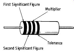
Fig. 1. Arrangement of color coding bands.
Composition ( carbon) resistors are generally marked with a fourth band to indicate the tolerance. If the fourth band is silver, the resistor's tolerance is +10 percent. A gold band indicates a tolerance of ±5 percent. Thus, if the nominal value of a resistor is 10,000 ohms, and it has a silver band, its actual resistance value ranges between 9,000 and 11,000 ohms. If the resistor has no tolerance band, its tolerance is assumed to be +20 percent.
When a carbon resistor is used in a new circuit design, the actual power dissipated by the resistor should be about one half the rated wattage of the resistor.
Composition (carbon) resistors are furnished with axial tinned copper leads to connect the resistor into the circuit.
These leads allow the resistor to be self-supporting.
Precision Carbon-Film Resistors
This type of resistor is intended for applications requiring extremely close resistance tolerance ± 1 percent or better. The carbon film resistor is generally a low wattage (½ to 2 watts) unit, and is used primarily in precision test equipment.
Wirewound Resistors
When higher power dissipation is required, wirewound resistors are used. These resistors consist of a ceramic tube over which a layer of resistance wire is wound. The resistance winding is in turn covered by a layer of ceramic to protect the winding (see Fig. 2).
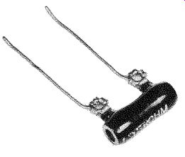
Fig. 2. Fixed wirewound resistor.
Wirewound resistors are available with resistance values ranging from a fraction of an ohm to approximately 100K ohms. Power ratings range from 2 to 500 watts.
Unlike a composition resistor, which has its resistance values indicated by colored bands, a wirewound resistor has its resistance values printed on its side.
The normal tolerance value of the wirewound resistor is
± 10 percent, although closer tolerance units are available.
Adjustable wirewound resistors are also available in which the resistance may be varied with an adjustable slider moved along an exposed portion of the winding, as shown in Fig. 3.
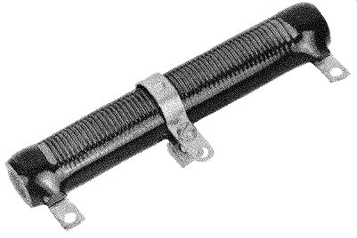
Fig. 3. Adjustable wirewound-resistor.
Low wattage (2-20 watts) wirewound resistors are generally provided with wire leads for their connection into the circuit. Due to the relatively light weight of these resistors, these connecting leads also provide mechanical sup port for the resistor. Resistors with higher wattage (25-500 watts) are generally provided with brackets for mounting and solder lugs at each end of the resistor body for electrical connections.
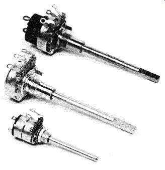
Fig. 4. Potentiometers.
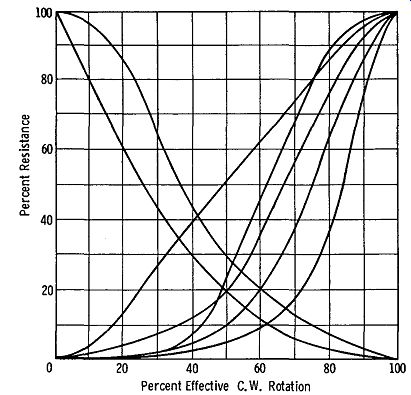
Fig. 5. Potentiometer resistance tapers.
POTENTIOMETERS
A potentiometer (Fig. 4) is a continuously variable resistor used in such applications as volume and tuning controls.
Standard potentiometers are available in two basic types; composition ( carbon) and wirewound. The composition potentiometer is a low wattage unit (½ to 2 watts). Wirewound potentiometers are available in wattages ranging from 2 to 300 watts or more.
Potentiometer Tapers
Potentiometers of the composition type are available with various resistance tapers, as shown by the graph in Fig. 5. A potentiometer with a linear taper means that its resistance will vary linearly (from zero to maximum) with respect to its shaft rotation. A potentiometer with a logarithmic taper means that its resistance will vary from zero to maximum in a logarithmic manner with respect to its shaft rotation. The latter type of taper, often referred to as an "audio taper," is used in volume controls.
CAPACITORS
Capacitors, as well as resistors, form the "backbone" of electronic circuitry, and are available in a wide variety of physical and electrical configurations to suit the particular application.
Paper Capacitors
Perhaps the most common of all capacitors is the paper capacitor. Used extensively in coupling and bypass applications, paper capacitors are available in a wide range of capacitance values and voltage ratings. Typical capacitance values range from .0001 µ.F to 1.0 µ.F, with voltage ratings ranging from 200 to 10,000 volts and more for specialized units.
A paper capacitor is made by rolling alternate layers of aluminum foil and chemically treated paper into a cylindrical shape as shown in Fig. 6. Connecting leads are attached to alternate foil sides.
Paper capacitors should not be used in radio-frequency tuned circuits because they are not electrically stable enough.
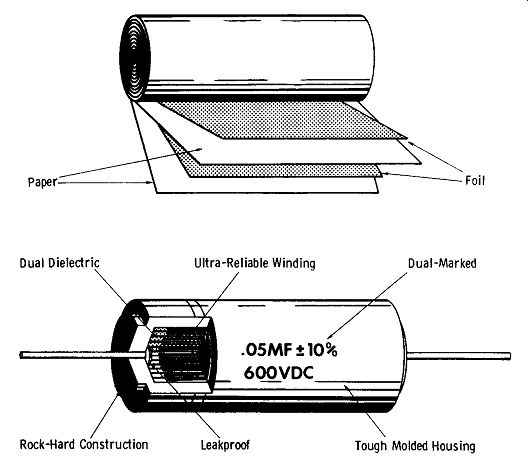
Fig. 6. Paper tubular
capacitor.
Mica Capacitors
Mica capacitors are used extensively in rf tuned circuits, since they are considerably more stable electrically than paper capacitors.
The construction of a typical mica capacitor is illustrated in Fig. 7, and consists of alternate thin sheets of aluminum foil separated by thin mica sheets. Leads are connected to the foil sheets, and the assembly is encased in a plastic housing.
Silver-mica capacitors have a silver coating (which acts as the conducting material) deposited on opposite faces of the mica sheets. Connecting leads are attached to the silver.
Silver-mica capacitors are more stable electrically than foil-type capacitors, and are used in high-stability frequency determining circuits. Silver-mica capacitors are available in tolerances ranging from +5 percent to +1 percent or better.
(A) Construction of a typical mica capacitor.
(B) Flat mica capacitor.
(C) High-capacitance mica capacitor.
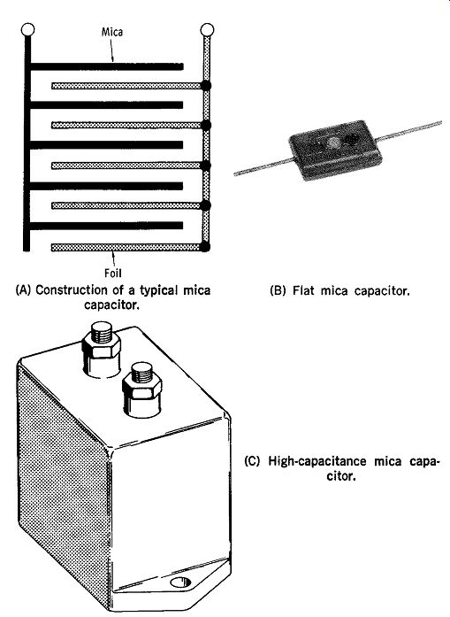
Fig. 7. Fixed mica capacitors.
Disc Capacitors
A disc capacitor (shown in Fig. 8) consists of a thin wafer of ceramic material with a thin coat of silver de posited on opposite sides. Leads are attached to these silver electrodes, and the wafer is encapsulated in a protective coating.
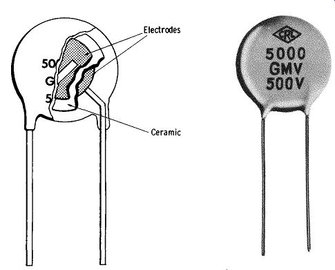
Fig. 8. Disc ceramic capacitor.
Disc ceramic capacitors are used primarily as coupling and bypass portions of radio frequency-circuits, rather than frequency-determining elements. Exceptions to this are special, close-tolerance, high-stability ceramic capacitors which are especially designed for use in resonant circuits.
Disc ceramic capacitors are commonly available in capacitance values ranging from 47 pF to .05 µF. Voltage ratings range from 600 to 3000 volts.
Special low-voltage, high-capacitance disc capacitors are also available for use in transistor circuits. These capacitors have voltage ratings ranging from 12 to 100 volts. Capacitance ratings of these units range from .05 µF to .47 µF and higher.
Electrolytic Capacitors
Electrolytic capacitors have a high capacitance-to-size ratio, and are used extensively in the filter section of de power supplies and transistor circuits.
Fig. 9 shows the can and tubular types, which are the most widely used electrolytic capacitors. (A) Tubular capacitor. (8) Can type capacitor.
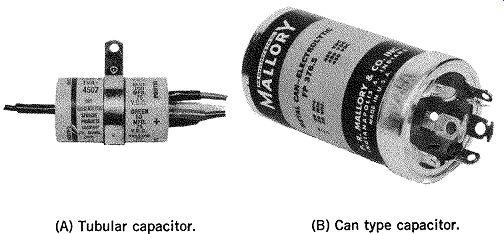
Fig. 9. Tubular and can electrolytic capacitor.
Electrolytic capacitors are available in capacitance values ranging from less than 1µ,F to 10,000 µ,F or more. Common voltage ratings range from 5 to 700 volts.
High heat tends to increase electrolytic capacitor leakage current, causing further internal heating of the capacitor and the vicious circle continues. Increased leakage current shortens the life of the capacitor and degrades filtering action when it is used in power supply service.
When placing electrolytic capacitors in service, it is important that their polarity be observed. If connected in correctly into a circuit, an electrolytic capacitor will be destroyed almost immediately.
Variable Capacitors
Variable capacitors are used primarily for varying the frequency of a resonant circuit. Receiver-type variable capacitors are generally available in capacitance ranges from 10 pF to 365 pF. Transmitting-type variable capacitors are available in similar capacitance values and with voltage breakdown ratings up to 20 kV and higher.
Variable capacitors are available in single, dual-, and three-section units. Fig. 10 shows a three-section unit.
Two- and three-section variable capacitors are used primarily in the tuning sections of superheterodyne receivers, where it is necessary to simultaneously tune several resonant circuits.
Made by J. W. Miller Co.
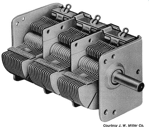
Fig. 10. Three-section variable capacitor.
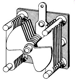
Fig. 11. Butterfly capacitor.
Transmitting variable capacitors have an additional rating-voltage breakdown. This rating refers to the maximum voltage that may be applied to the capacitor before voltage breakdown occurs between the capacitor plates. Therefore, when purchasing a transmitting-type capacitor, be sure that the voltage rating of it is sufficient for the voltages encountered in the circuits. These voltages can be obtained from the tube manual or transmitter circuit diagrams.
"Butterfly capacitors," shown in Fig. 11, are used in balanced rf circuits, where it is necessary to maintain electrical symmetry.
Trimmer Capacitors
Fig. 12 shows two types of trimmer capacitors. The trimmer capacitor shown in Fig. 12A is called a "compression" trimmer and consists of one or more metal (aluminum) sheets separated by sheets of mica. The aluminum sheets are under spring tension so that as they are squeezed together by the turning of an adjusting screw, their physical spacing and, hence, trimmer capacitance is varied.
(A) Compression type capacitor. (B) Air-dielectric type capacitor.
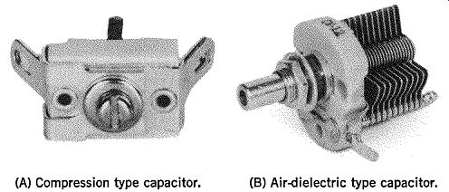
Fig. 12. Trimmer capacitors.
Fig. 12B illustrates a trimmer capacitor with an air dielectric. Actually, this is a miniature version of the standard size air variable capacitor. Air trimmer capacitors usually have a screwdriver-adjustable short shaft in place of the longer shaft employed in standard air variables.
Trimmer capacitors are also referred to as "padder" capacitors.
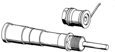
Fig. 13. Piston capacitors.
Fig. 13 shows a variable capacitor known as a "piston" capacitor. One plate consists of an outer metal cup. A glass sleeve fits inside this cup, and a second metal cup ("piston") is fitted inside the glass sleeve. As the "piston" is moved up and down within the glass sleeve, the capacitance is varied.
Due to the small physical area of the inner and outer metal parts of the piston capacitor, its maximum capacitance is quite low, usually less than 50 pF. Trimmer capacitors are used primarily to add small amounts of capacitance to tuned circuits. In effect, they "trim" the capacitance to the required value.
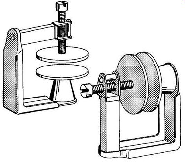
Fig. 14. Neutralizing capacitors.
Another type of capacitor, known as a neutralizing capacitor (Fig. 14), is used to provide the negative feedback capacitance in a triode rf amplifier stage. Without this neutralizing capacitance, the grid-plate interelectrode capacitance in the triode would cause oscillation of the amplifier.
The typical neutralizing capacitor consists of a fixed metal disc which forms one plate of the capacitor. The other plate is a movable metal disc whose position with respect to the fixed disc, is varied with a threaded drive screw. As the distance between the two discs is increased, the capacitance decreases.
TRANSFORMERS
Transformers represent another major category of electronic components. There are many types, including audio, power filament, pulse, and rf transformers.
Power Transformers
Perhaps the transformer you will encounter most in your work with electronics is the power transformer. The power transformer is designed to convert the 120-volt power-line voltage applied to its primary winding into one or more separate voltages. These voltages may be either higher or lower than the applied primary voltage. For example, a typical power transformer designed to power a vacuum-tube circuit will furnish a high voltage (200 volts and up) which is rectified to provide the proper de plate voltage for the tubes in the circuit. In addition, one or more separate low voltage windings (2.5, 3.5, 6.3, etc.) are provided to furnish voltage for the heaters of the tubes.
Chart 1 shows the accepted color code for the leads of the power transformers commonly used in electronic circuitry. The leads connected to the primary winding are black and red, or sometimes black and yellow. The high voltage secondary end leads are identified with red, and the center tap lead with red-yellow.
Fig. 15 shows a typical power transformer. The power transformer's filament winding is identified by two green leads, and if the filament winding has a center tap, it is identified by a green-yellow lead. Rectifier filament winding leads are yellow, if included.
--------
Primary Leads .............
Black If tapped: Common .... Black Tap ...........
Black and Yellow Striped Finish ............. Black and Red Striped High-Voltage Plate Winding ............... Red Center-Tap . Red and Yellow Striped Rectifier Filament Winding ........... Yellow Center-Tap ................. Yellow and Blue Striped Filament Winding No. 1 . Green Center-Tap ............... Green and Yellow Striped Filament Winding No. 2 . Brown Center-Tap ............... Brown and. Yellow Striped Filament Winding No. 3 ... Slate Center-Tap ................. Slate and Yellow Striped
Chart 1 . Power Transformer Leads Color Code
--------
Made by Stanco, Products, Essex Wire Corp.
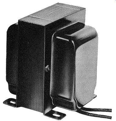
Fig. 15. Typical power transformer.
Typical receiver-type power transformers have secondary voltage ratings ranging from 125 to 600 volts. High voltage secondary current ratings range from 10 to 200 mA. Typical filament voltages are almost exclusively 6.3 volts, although some older power transformers offer 2.5-volt filament windings. Current ratings for filament windings range from 0.6 to 10 amperes or more. Rectifier filament winding voltages are usually 5 volts at current ratings of several amperes.
Power transformers designed to power semiconductor circuits usually have only a single secondary winding. The voltage rating of this winding will depend on the circuit requirements, usually ranging from 6 to 40 volts or more.
The current rating may be from a few milliamperes to several amperes. Since these transformers are generally used to power a bridge-type semiconductor rectifier, the secondary winding is not center-tapped.
Another type of power transformer is known as a "plate" transformer. This type has a single high-voltage secondary winding, and is designed to provide plate voltage for tubes in transmitting and industrial equipment. Secondary voltage ratings of plate transformers range from less than 1000 volts to 10 kV or more. Secondary current ratings range from 100 mA to several amperes.
Filament Transformers
The filament transformer (a variation of the power transformer) generally has a single secondary winding, and is designed to furnish operating power to the filaments of vacuum tubes (see Fig. 16).
Tips on Using Power Transformers
When mounting power transformers-power, filament, plate, etc.--it is important that the transformer be mounted well away from any low-level portions of the circuit when the transformer is used to power audio-frequency equipment such as audio amplifiers. This is because the ac field radiated from the transformer can be picked up by a high-gain, low level stage, thereby causing hum in the output signal of the amplifier.
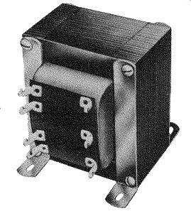
Fig. 16. Typical filament transformer.
Made by Stancor Products, Essex Wire Corp.
When purchasing a transformer, note that the secondary voltage of the transformer is listed as, say, 300 VCT. This denotes that when used with a full-wave rectifier, the output from the rectifier will be only 150 volts. This is because 150 volts appears on each half of the secondary winding with respect to the centertap. On the other hand, some transformer manufacturers list their secondary voltages as, say, 300-0-300 volts. This means that 300 volts appear on each side of the center tap, and thus, 300 volts will appear at the output of the full-wave rectifier connected to this winding.
When a higher voltage than is obtainable from a full wave rectifier configuration is desired, a bridge rectifier may be used. This will yield twice the output voltage from the same secondary winding. For example, a power transformer with a secondary voltage of 300 volts, C.T. will provide 150 volts when used with a full-wave rectifier and 300 volts when used with a bridge rectifier. However, the total power delivered by the secondary must remain the same in both cases. Therefore, if the bridge rectifier is used, the current drawn from the secondary must be cut in half to keep within the VA rating of the transformer.
When selecting a filament transformer to furnish operating voltage for a rectifier, it is important that the primary-to-secondary insulation of the transformer be high enough so that there will be no voltage breakdown between the secondary and primary windings. The maximum voltage that may be applied between primary and secondary windings is generally given for filament transformers by the manufacturer.
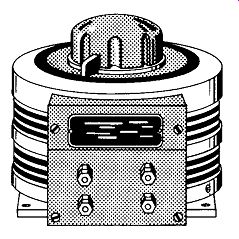
Fig. 17. Variable-voltage transformer.
Variable Transformers (Variacs)
Fig. 17 shows a handy device that enables one to continuously vary the applied voltage (120 volts ac) from 0 to maximum. Unlike a variable power rheostat, which drops voltages by means of heat loss, the variable transformer is extremely efficient. Variable transformers are available in current ratings ranging from less than 1 ampere to 20 amperes or more.
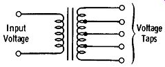
Fig. 18. Voltage-adjusting transformer.
Voltage Adjusting Transformers
A variation of the variable transformer is shown in Fig. 18. Instead of a continuously variable output, the voltage adjusting transformer has a series of taps on its secondary winding which provide different levels of secondary voltage. These taps are often provided so that the secondary voltage is slightly higher than the applied primary voltage. As an example of this, a voltage-adjusting transformer may be used to boost a lower-than-normal line voltage, say, 105 volts, up to 120 volts.
Audio Transformers
Transformers that fall into this category include audio input, audio interstage, and audio output transformers.
Audio Output Transformers
The audio output transformer is intended to couple the output of a vacuum-tube or transistor audio amplifier to a speaker.
Audio output transformers have definite characteristics, the most important of which are:
1. Proper impedance match between the source (amplifier plate or collector circuit) and load,
2. Adequate power handling capability, and
3. Adequate frequency response.
Proper impedance matching means that the proper load impedance should be reflected back to the amplifier output stage for the given load (speaker). Manufacturer specifications indicate the proper transformer for the particular amplifier output stage/load combination. "Universal" audio output transformers are available which greatly simplify the matching. Such a transformer is shown in Fig. 19.
Multiple secondary taps permit a wide range of impedance matching arrangements.
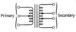
Fig. 19. Impedance-matching audio transformer.
The power handling rating of the output transformer depends on the output power of the amplifier. For example, a 15-watt audio amplifier should employ an output transformer capable of handling 15 watts, etc. There is one point to keep in mind: Most manufacturers of standard audio output transformers do not correctly rate their transformers. One of their transformers rated at, say 10 watts will actually handle about 5 watts without introducing excessive harmonic distortion. Therefore, as a rule of thumb, it is a good idea to select an output transformer with a power rating 5 or 10 watts higher than the rated output of the amplifier stage. (This does not apply to the higher quality "high fidelity" output transformers which are rated honestly as far as power handling capacity is concerned.)
Fig. 20 shows a typical output transformer.
Made by Stanco, Products, Essex Wire Corp.
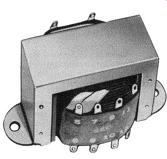
Fig. 20. Typical audio-output transformer.
The frequency response of an audio output transformer is an important consideration when it is to be used in a high-fidelity amplifier. Generally speaking, the output transformer should have a frequency range of from at least 20 Hz to 20 kHz. If negative feedback is to be placed around the output transformer, the frequency bandwidth of the transformer should extend beyond this range.
Air-Core Coils and Transformers
Examples of air-core coils and transformers include intermediate frequency (i-f) transformers, radio-frequency (rf) chokes and traps, antenna and rf transformers, etc.
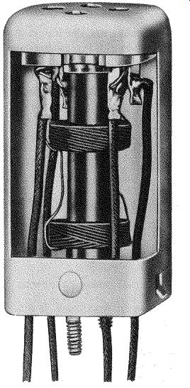
Fig. 21. Intermediate-frequency (i-f) transformer.
I-F Transformers
Fig. 21 illustrates one of the more common types of air-core transformers. It is known as an intermediate frequency transformer because it is used in the intermediate frequency amplifier sections of radio and tv receivers. It consists of two windings placed on a fiber or ceramic form.
Generally, both the primary and secondary windings are tuned to the operating frequency by mica compression trimmer capacitors.
In some i-f transformers, ferrite slugs are used to tune the windings to the desired frequency.
FILTER CHOKES
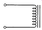
Fig. 22. Filter choke.
A filter choke (Fig. 22) is a device used in the filter section of a de power supply. The two major ratings of a filter choke are the inductance and current rating. Fig. 23 is a photo of a typical low-current filter choke.
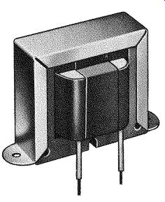
Fig. 23. Typical low-current filter choke. Made by J. W. Miller Cu.
The inductance of a filter choke is expressed in henrys, and may range from less than 1 henry to 50 or more.
The current rating of a choke may range from a few milliamperes to several amperes. It is important that the maximum current rating of the choke not be exceeded. If more than the rated value of current is drawn through the choke, the inductance will decrease, which in turn will decrease the effectiveness of the choke in the filtering circuit.
When used in high-voltage circuits, the insulation between the winding and mounting frame of the choke must be sufficient to prevent voltage breakdown.
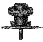
Fig. 24. Radio-frequency (rf) choke. Made by J. w. Miller Co.
RF Chokes
An rf choke (Fig. 24) consists of a winding placed over a fiber or ceramic form. Often, the winding is arranged in a "pie" to reduce the distributed capacitance of the choke.
Frequently, in an effort to increase the inductance of an rf choke, a ferrite core is employed.
Also see: Basics of Electricity and Electronics with Projects
AMAZON multi-meters discounts AMAZON oscilloscope discounts