ELECTRONIC CIRCUIT DESIGN
The type of circuit layout used for almost all analog (i.e. non-digital) magnetic tape recorders is as shown, in block diagram form, in FIG. 18.
The critical parts of the design, in respect of added circuit noise, are the replay amplifier, and the bias/erase oscillator. They will be considered separately.
It should also be noted that the mechanical design of both the erase and record heads can influence the noise level on the tape. This is determined by contact profile and gap design, consideration of which is beyond the scope of this SECTION.
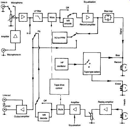
FIG. 18 Schematic layout of the 'building blocks' of a magnetic tape recorder.
The replay amplifier:
Ignoring any noise reduction decoding circuitry, the function of this is to amplify the electrical signal from the replay head, and to apply any appropriate frequency response equalization necessary to achieve a substantially uniform frequency response. The design should also ensure the maximum practicable s/n ratio for the signal voltage present at the replay head.
It has been noted previously that the use of very narrow replay head gaps, desirable for good high frequency and transient response, will reduce the signal output, if only because there will be less tape material within the replay gap at any one time. This makes severe demands on the design of the replay amplifier system, especially in the case of cassette recorder systems, where the slow tape speed and narrow tape track width reduces the extent of magnetic induction.
In practice, the mid-frequency output of a typical high quality cassette recorder head will only be of the order of 1 mV, and, if the overall S/N ratio of the system is not to be significantly degraded by replay amplifier noise, the 'noise floor' of the replay amp., should be of the order of 20 dB better than this. Taking 1 mV as the reference level, this would imply a target noise level of -72 dB if the existing tape S/N ratio is of the order of -52 dB quoted above.
The actual RMS noise component required to satisfy this criterion would be 0.25 µs , which is just within the range of possible circuit performance, provided that care is taken with the design and the circuit components.
The principal sources of noise in an amplifier employing semiconductor devices are:
1. 'Johnson' or 'thermal' noise, caused by the random motion of the electrons in the input circuit, and in the input impedance of the amplifying device employed (minimized by making the total input circuit impedance as low as possible, and by the optimum choice of input devices)
2. 'shot' noise, which is proportional to the current flow through the input device, and to the circuit bandwidth
3. 'excess', or ?//' , noise due to imperfections in the crystal lattice, and proportional to device current and root bandwidth, and inversely proportional to root frequency
4. collector-base leakage current noise, which is influenced by both operating temperature and DC supply line voltage
5. surface recombination noise in the base region.
Where these are approximately calculable, the equations shown below are appropriate.
Johnson (thermal noise) =
Shot noise =
Modulation noise =
… where 'delta f ' is the bandwidth (Hz), K = 1.38 x 10^-23 , T is the temperature (Kelvin), q the electronic charge (1.59 x 10^-19 Coulombs), f is the operating frequency and R the input circuit impedance.
In practical terms, a satisfactory result would be given by the use of silicon bipolar epitaxial-base junction transistor as the input device, which should be of PNP type. This would take advantage of the better surface recombination noise characteristics of the n-type base material, at an appropriately low collector to emitter voltage, say 3-4 V, with as low a collector current as is compatible with device performance and noise figure, and a base circuit impedance giving the best compromise between 'Johnson' noise and device noise figure requirements.
Other devices which can be used are junction field-effect transistors, and small-signal V-MOS and T-MOS insulated-gate type transistors. In some cases the circuit designer may adopt a slightly less favorable input configuration, in respect of S/N ratio, to improve on other performance characteristics such as slew-rate balance or transient response.
Generally, however, discrete component designs will be preferred and used in high quality machines, although low-noise integrated circuit devices are now attaining performance levels where the differences between IC and discrete component designs are becoming negligible.
Typical input amplifier circuit designs by Sony, Pioneer, Technics, and the author, are shown in Figs 19-22.
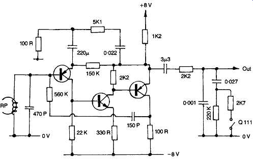
FIG. 19 Cassette deck replay amplifier by Sony (TCK81).
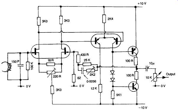
FIG. 20 Very high quality cassette recorder replay amplifier due to Pioneer
(CT-A9).
In higher speed reel-to-reel recorders, where the signal output voltage from the replay head is higher, the need for the minimum replay amplifier noise is less acute, and low-noise IC op. amplifiers, of the type designed for audio purposes will be adequate. Examples are the Texas Instruments TL071 series, the National Semiconductor LF351 series op amps. They offer the advantage of improved circuit symmetry and input headroom.
If the replay input amplifier provides a typical signal output level of 100 mV RMS, then all the other stages in the signal chain can be handled by IC op. amps without significant degradation of the S/N ratio. Designer preferences or the desire to utilize existing well tried circuit structures may encourage the retention of discrete component layouts, even in modern equipment.
However, in mass-produced equipment aimed at a large, low-cost, market sale, there is an increasing tendency to incorporate as much as possible of the record, replay, and noise reduction circuitry within one or two complex, purpose-built ICs, to lessen assembly costs.
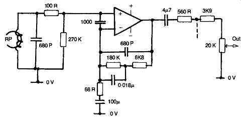
FIG. 21 Combined record/replay amplifier used by Technics, shown in replay
mode (RSX20).
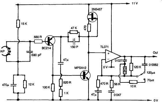
FIG. 22 Complete cassette recorder replay system, used in portable machine.
REPLAY EQUALIZATION
This stage will usually follow the input amplifier stage, with a signal level replay gain control interposed between this and the input stage, where it won’t degrade the overall noise figure, it will lessen the possibility of voltage overload and 'clipping' in the succeeding circuitry.
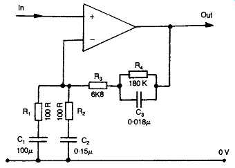
FIG. 23 RC components network used in replay amplifier to achieve frequency
response equalization.
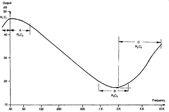
FIG. 24 Cassette recorder replay response given by circuit layout shown in
FIG. 23y indicating the regions affected by the RC component values.
Opinions differ among designers on the position of the equalization network. Some prefer to treat the input amplifier as a flat frequency response stage, as this means the least difficulty in obtaining a low input thermal noise figure. Others utilize this stage for the total or initial frequency response shaping function.
In all cases, the requirement is that the equalized replay amplifier response shall provide a uniform output frequency response, from a recorded flux level having the characteristics shown in FIG. 8, ignoring for the moment any frequency response modifications which may have been imposed by the record-stage noise reduction processing elements, or the converse process of the subsequent decoding stage.
Normally, the frequency response equalization function will be brought about by frequency sensitive impedance networks in the feedback path of an amplifier element, and a typical layout is shown in FIG. 23.
Considering the replay curve shown in FIG. 24, this can be divided into three zones, the flattening of the curve, in zone '?' , below 50 Hz, in accordance with the LF 3180 µ8 time-constant employed, following TBL. 3, in almost all recommended replay characteristics, the leveling of the curve, in zone ?' , beyond a frequency determined by the HF time constant of TBL. 3, depending on application, tape type, and tape speed.
Since the output from the tape for a constant remanent flux will be assumed to increase at a +6 dB/octave rate, this leveling-off of the replay curve is equivalent to a 4-6 dB/octave HF boost. This is required to correct for the presumed HF roll-off on record, shown in FIG.
Finally, there is the HF replay boost of zone C\ necessary to compensate for poor replay head HF performance. On reel-to-reel recorders this effect may be ignored, and on the better designs of replay head in cassette recorders the necessary correction may be so small that it can be accomplished merely by adding a small capacitor across the replay head, as shown in the designs of Figs 19-22. The parallel resonance of the head winding inductance with the added capacitor then gives an element of HF boost.
With worse replay head designs, some more substantial boost may be needed, as shown in in FIG. 23.
A further type of compensation is sometimes employed at the low frequency end of the response curve and usually in the range 30-80 Hz, to compensate for any LF ripple in the replay response, as shown in FIG. 10. Generally all that is attempted for this kind of frequency response flattening is to interpose a tuned LF 'notch' filter, of the kind shown in FIG. 25 in the output of the record amp, to coincide with the first peak in the LF replay ripple curve.
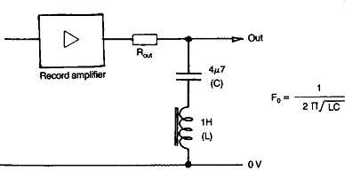
FIG. 25 Notch filter in record amplifier, used to lessen LF ripple effects.
BIAS OSCILLATOR CIRCUITS
The first major requirement for this circuit is a substantial output voltage swing - since this circuit will also be used to power the 'erase' head, and with some tapes a large erase current is necessary to obtain a low residual signal level on the erased tape. Also needed are good symmetry of waveform, and a very low intrinsic noise figure, since any noise components on the bias waveform will be added to the recorded signal.
The invariable practical choice, as the best way of meeting these requirements, is that of a low distortion HF sine waveform.
Since symmetry and high output voltage swing are both most easily obtained from symmetrical 'push-pull' circuit designs, most of the better modern recorders employ this type of layout, of which two typical examples are shown in Figs 26 and 27. In the first of these, which is used in a simple low-cost design, the erase coil is used as the oscillator inductor, and the circuit is arranged to develop a large voltage swing from a relatively low DC supply line.
The second is a much more sophisticated and ambitious recorder design.
Where the actual bias voltage level is automatically adjusted by microcomputer control within the machine to optimize the tape recording characteristics. The more conventional approach of a multiple winding transformer is employed to generate the necessary positive feedback signal to the oscillator transistors.
In all cases great care will be taken in the choice of circuitry and by the use of high 'Q' tuned transformers to avoid degrading the purity of the waveform or the S/N ratio.
In good quality commercial machines there will generally be both a switch selectable bias level control, to suit the IEC designated tape types (1-4) and a fine adjustment. This latter control will usually be a pair of variable resistors, in series with separate small capacitors, in the feed to each recording channel, since the high AC impedance of the capacitor tends to restrict the introduction of lower frequency noise components into the record head. It also serves to lessen the possibility of recording signal cross-talk from one channel to the other.
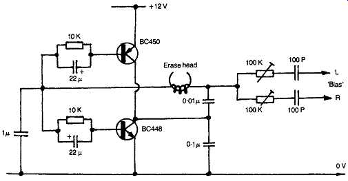
FIG. 26 High-output, low-distortion, bias / erase oscillator used in cassette
recorder.
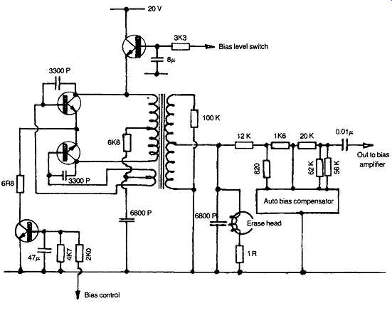
FIG. 27 High-quality bias oscillator having automatic bias current adjustment
facilities (Pioneer CT-A9).
THE RECORD AMPLIFIER
Referring to the block diagram of FIG. 18, the layout of the recording amplifier chain will normally include some noise reduction encoding system (Dolby A or equivalent, and/or Dolby HX, in professional analogue-type tape recorders, or Dolby B or C in domestic machines). The operation of this would be embarrassed by the presence of high-frequency audio components, such as the 19 kHz FM 'pilot tone' used in stereo broadcasts to regenerate the 38 kHz stereo sub-carrier.
For this reason, machines equipped with noise reduction facilities will almost invariably also include some low-pass filter system, either as some electronic 'active filter' or a simple LC system, of the forms shown in FIG. 28. Some form of microphone amplifier will also be provided as an alternative to the line inputs. The design of this will follow similar low noise principles to those essential in the replay head amplifier, except that the mic. amplifier will normally be optimized for a high input circuit impedance. A typical example is shown in FIG. 29.
As mentioned above, it’s common (and good) practice to include a 'muting' stage in the replay amp line, to restrict the audibility of the amplifier noise in the absence of any tape signal. A similar stage may be incorporated in the record line, but in this case the VU or peak recording meter will require to derive its signal feed from an earlier stage of the amplifier. Thus the input signal level can still be set with the recorder at 'pause'. The recording amplifier will be designed to deliver the signal to the record head at an adequate amplitude, and with low added noise or distortion, and in a manner tolerant of the substantial HF bias voltage present at the record head.
Contemporary design trends tend to favor record heads with low winding impedances, so the record amplifier must be capable of coping with this.
As noted above, the design of the record amplifier must be such that it won’t be affected by the presence of the HF bias signal at the record head.
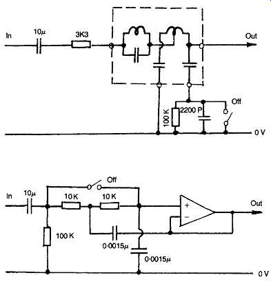
FIG. 28 LC and active low-pass filter systems used to protect noise reduction
circuitry from spurious HF inputs.
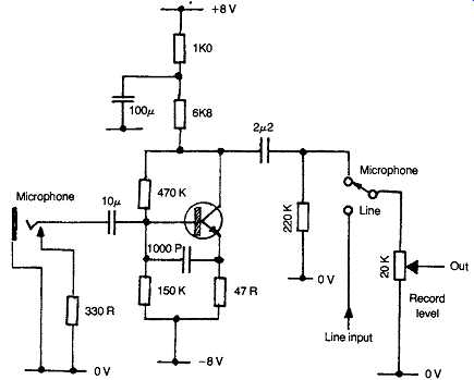
FIG. 29 Single stage microphone input amplifier by Sony (TCK-81).
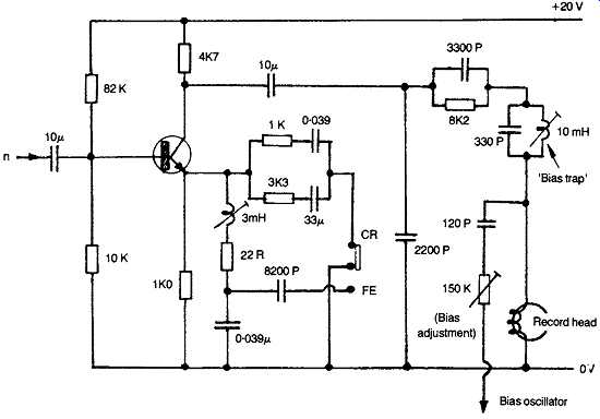
FIG. 30 Record output stage, from Pioneer, showing bias trap and LC equalization
components (CT4141-A).
Several approaches can be chosen. One is to employ an amplifier with a very high output impedance, the output signal characteristics of which won’t be influenced by superimposed output voltage swings.
Another is to interpose a suitable high value resistor in the signal line between the record amp. and the head. This also has the benefit of linearizing the record current versus frequency characteristics of the record system. If the record amplifier has a low output impedance, it will cause the intruding bias frequency signal component to be greatly attenuated in its reverse path.
However, the simplest, and by far the most common, choice is merely to include a parallel-tuned LC rejection circuit, tuned to the HF bias oscillator frequency, in the record amplifier output, as shown in the circuit design of FIG. 30. Some very advanced recorder designs actually use a separate mixer stage, in which the signal and bias components can be added before they are fed to the record head. In this case the design of the output stage is chosen so that it can handle the total composite (signal + bias) voltage swing without cross-modulation or other distortion effects.
RECORDING LEVEL INDICATION
This is now almost exclusively performed in domestic type equipment by instantaneously acting light-emitting diodes, adjusted to respond to the peak recording levels attained. There are several purpose-built integrated circuits designed especially for this function.
In earlier instruments, where moving coil display meters were used, great care was necessary to ensure that the meter response had adequate ballistic characteristics to respond to fast transient signal level changes.
This invariably meant that good performance was expensive.
It’s notable that professional recording engineers still prefer to use meter displays, the ballistic characteristics of which are normally precisely controlled, and to the ASA C16-5 specification. However, the indication given by these may be supplemented by LED-type peak level indication.
TAPE DRIVE MOTOR SPEED CONTROL
Few things have a more conspicuous effect upon the final performance of a tape recorder system than variations in the tape speed. Electronic servo systems, of the type shown in schematic form in FIG. 31, are increasingly used in better class domestic machines (they have been an obligatory feature of professional recorder systems for many years) to assure constancy of tape travel.
In arrangements of this kind, the capstan drive motors will either be direct current types, the drive current of which is increased or decreased electronically depending on whether the speed sensor system detects a slowing or an increase in tape speed. Alternatively, the motors may be of 'brushless' AC type, fed from an electronically generated AC waveform, the frequency of which is increased or decreased depending on whether a positive or a negative tape speed correction is required.
With the growing use of microprocessor control and automated logic sequences to operate head position, signal channel and record/replay selection, and motor control, the use of electronically generated and regulated motor power supplies is a sensible approach. The only problem is that the increasing complexity of circuitry involved in the search for better performance and greater user convenience may make any repairs more difficult and costly to perform.
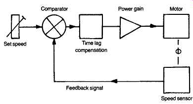
FIG. 31 Schematic layout of speed control servo-mechanism.
PROFESSIONAL RECORDING EQUIPMENT
This is aimed at an entirely different type of use to that of the domestic equipment, and is consequently of different design, with a different set of priorities.
Domestic tape cassette recorders are used most commonly for transferring program material from radio broadcasts gramophone or other tape recordings, or spontaneous (i.e., non-repeatable) 'live' events, to tape and the finished recording is made for the benefit of the recordist or the participants. No editing is desired or practicable. In contrast, in commercial/professional work it’s likely that the final product will be closely scrutinized for imperfections, and will be highly edited.
Moreover, in broadcasting or news applications, it’s essential that time synchronization , for example with pictures, be practicable.
Also, since the recording process is just one step in a necessarily profitable commercial operation, professional machines must be rugged, resistant to misuse, and reliable. The cost of the equipment, except as dictated by competitive pressures between rival manufacturers, will be of a secondary consideration, and its physical bulk will be less important than its ease of use.
These differences in use and outlook are reflected in the different types of specification of professional recording systems, and these are listed below.
GENERAL DESCRIPTION
Mechanical
Professional tape recording machines will invariably be reel-to-reel recording as 'half-track', or occasionally as 'quarter-track' on 1/4 in. tape, or as 8-track, 16-track, 24-track or 32-track, on x h in., 1 in. or 2 in. wide tape.
(Because of the strong influence of the USA in the recording field, metric dimensions are very seldom used in specifying either tape widths or linear tape speeds of professional equipment.) Even on half-track machines, facilities are now being provided for time code marking as are more generally found on multi-track machines by way of an additional channel in the central 2.25 mm dead band between the two stereo tracks.
This allows identification of the time elapsed since the start of the recording as well as the time remaining on the particular tape in use. This information is available even if the tape is removed and replaced, part wound. (It’s customary for professional recorders, copied now by some of the better domestic machines, to indicate tape usage by elapsed-time displays rather than as a simple number counter.) Also available is the real time - as in the conventional clock sense - and any reference markers needed for external synchronization or tape editing.
The mechanisms used will be designed to give an extremely stable tape tension and linear tape speed, with very little wow or flutter, a switched choice of speeds, and provision for adjusting the actual speed, upwards or downwards, over a range - customarily chosen as seven semitones - with facility for accurate selection of the initial reference tape speed. It’s also customary to allow for different sized tape spools, with easy and rapid replacement of these.
The high power motors customarily used to ensure both tape speed stability and rapid acceleration - from rest to operating speed in 100 ms is attainable on some machines - can involve significant heat dissipations.
So the bed-plate for the deck itself is frequently a substantial die-casting, of up to two inches in thickness, in which the recesses for the reels, capstans and heads are formed by surface machining . The use of ancillary cooling fans in a studio or sound recording environment is understandably avoided wherever possible.
To make the tape speed absolutely independent of mains power frequency changes, it’s common practice to derive the motor speed reference from a crystal controlled source, frequently that used in any microprocessor system used for other control, editing, and search applications.
Since the product will often be a commercial gramophone record or cassette recording, from which all imperfections must be removed before production, editing facilities - either by physically splicing the tape, or by electronic processing - will feature largely in any 'pro' machine. Often the tape and spool drive system will permit automatic 'shuttle' action, in which the tape is moved to and fro across the replay head, to allow the precise location of any edit point.
An internal computer memory store may also be provided to log the points at which edits are to be made, where these are noted during the recording session. The number and position of these may also be shown on an internal display panel, and the tape taken rapidly to these points by some auto-search facility.
Electrical
The electronic circuitry employed in both professional and domestic tape recorder systems is similar, except that their tasks are different. Indeed many of the facilities which were originally introduced in professional machines have been taken over into the domestic scene, as the ambitions of the manufacturers and the expectations of the users have grown.
In general outline, therefore, the type of circuit layout described above will be appropriate. However, because of the optional choice of tape speeds, provision will be made for different, switch-selectable, equalization characteristics and also, in some cases , for different LF compensation to offset the less effective LF recording action at higher tape speeds. Again, the bias settings will be both adjustable and pre-settable to suit the tape types used.
To assist in the optimization of the bias settings, built-in reference oscillators, at 1 kHz, 10 kHz, and sometimes 100 Hz, may be provided, so that the flattest practicable frequency response may be obtained.
This process has been automated in some of the more exotic cassette recorders, such as the Pioneer CT-A9, in which the bias and signal level is automatically adjusted when the recording is initiated, using the first eleven seconds worth of tape, after which the recorder resets itself to the start of the tape to begin recording. Predictably, this style of thing does not appeal greatly to the professional recording engineer! Whether or not noise reduction circuitry will be incorporated within the machine is a matter of choice. ‘Pro' equipment will, however, offer easy access and interconnection for a variety of peripheral accessories, such as remote control facilities and limiter and compressor circuitry, bearing in mind the extreme dynamic range which can be encountered in live recording sessions.
Commonly, also, the high-frequency headroom expansion system, known as the Dolby HX Pro will be incorporated in high quality analogue machines. This monitors the total HF components of the recorded signal, including both program material and HF bias, and adjusts the bias voltage output so that the total voltage swing remains constant. This can allow up to 6 dB more HF signal to be recorded without tape saturation.
In the interests of signal quality, especially at the high frequency end of the audio spectrum, the bias frequency employed will tend to be higher than in lower tape speed domestic machines. 240 kHz is a typical figure.
However, to avoid overheating in the erase head, caused by the eddy Current losses which would be associated with such a high erase frequency, a lower frequency signal is used, such as 80 kHz, of which the bias frequency employed is the third harmonic. This avoids possible beat frequency effects.
Very frequently, both these signals are synthesized by subdivision from the same crystal controlled master oscillator used to operate the internal microprocessor and to control the tape drive speed.
With regard to the transient response shortcomings of tape recording systems, referred to earlier, there is a growing tendency in professional analogue machines to employ HF phase compensation, to improve the step-function response. The effect of this is illustrated in FIG. 32, and the type of circuitry used is shown in FIG. 33.
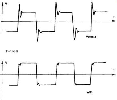
FIG. 32 Improvement in HF transient response, and consequent stereo image
quality, practicable by the use of HF phase compensation.
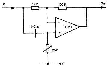
FIG. 33 HF phase-compensation circuit.
A major concern in professional work is the accurate control of both recording and output levels. Frequently the recording level meters will have switch selectable sensitivities for their 0VU position, either as the basic standard (0VU = 1 mW into 600 ohms = 0.774 V RMS) or as dB V (referred to 1 V RMS). It’s also expected that the OVU setting will be related accurately to the magnetization of the tape, with settings selectable at either 185, 250 or 320 nanoWebers/m.
Finally, and as a clear distinction from amateur equipment, professional units will all have provision for balanced line inputs from microphone and other program sources, since this greatly lessens the susceptibility of such inputs to mains induced hum and interference pick-up.
MULTI-TRACK MACHINES
Although single channel stereo machines have a place in the professional recording studio, the bulk of the work will be done on multi-track machines, either 8-, 16-, 24-, or 32-track. The reasons for this are various.
In the pop field , for example, it’s customary for the individual instrumentalists or singers in a group to perform separately in individual sound proofed rooms, listening to the total output, following an initial stereo mixing, on 'cans' (headphones). Each individual contributor to the whole is then recorded on a separate track, from which the final stereo master tape can be recorded by mixing down and blending, with such electronic sound effects as are desired.
This has several advantages, both from the point of view of the group, and for the recording company - who may offer a sample of the final product as a cassette, while retaining the master multi-track tape until all bills are paid. For the performers, the advantages are that the whole session is not spoilt by an off-color performance by any individual within the group, since this can easily be re-recorded. Also, i f the number is successful, another equally successful 'single' may perhaps be made , for example, by a re-recording with a different vocal and percussion section.
Moreover, quite a bit of electronic enhancement of the final sound can be carried out after the recording session, by frequency response adjustment and added reverberation, echo and phase, so that fullness and richness can be given , for instance, to an otherwise rather thin solo voice.
Studios possessing engineers skilled in the arts of electronic 'fudging' soon become known and sought after by the aspiring pop groups, whose sound may be improved thereby.
On a more serious level, additional tracks can be invaluable for recording cueing and editing information. They are also useful in the case, say, of a recording of a live event, such as an outside broadcast, or a symphony orchestra, in gathering as many possible signal inputs, from distributed microphones, as circumstances allow. The balance between these can then be chosen, during and after the event, to suit the intended use. A mono radio broadcast needing a different selection and mix of signal than , for example, a subsequent LP record, having greater dynamic range.
This 'multi-miking' of large scale music is frowned upon by some recording engineers. Even when done well, it may falsify the tonal scale of solo instrumentalists, and when done badly may cause any soloist to have an acoustic shadow who follows his every note, but at a brief time interval later. It has been claimed that the 'Sound Field' system will do all that is necessary with just a simple tetrahedral arrangement of four cardioid microphones and a four-channel recorder.
A technical point which particularly relates to multi-track recorder systems is that the cross-talk between adjacent channels should be very low. This will demand care in the whole record/replay circuitry, not just the record/replay head. Secondly, the record head should be usable, with adequate quality, as a replay head.
This is necessary to allow a single instrumentalist to record his contribution as an addition to a tape containing other music, and for it to be recorded in synchronism with the music which he hears on the monitor headphones, without the record head to replay head tape travel time lag which would otherwise arise.
The need to be able to record high-frequency components in good phase synchronism, from channel to channel, to avoid any cancellation on subsequent mixing, makes high demands on the vertical alignment of the record and replay head gaps on a multi-channel machine. It also imposes constraints on the extent of wander or slewing of the tape path over the head.
DIGITAL RECORDING SYSTEMS
The basic technique of digitally encoding an analogue signal entails repetitively sampling the input signal at sufficiently brief intervals, and then representing the instantaneous peak signal amplitude at each successive moment of sampling as a binary coded number sequence consisting of a train of 0s and 1s. This process is commonly termed 'pulse code modulation', or 'PCM'.
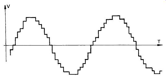
FIG. 34 'Staircase' type waveform resulting from the digital encoding! decoding
process. (1300 Hz sine-waveform illustrated as sampled at 44.1 kHz, and at
4-bit resolution).
The ability of the encoding process to resolve fine detail in the analogue waveform ultimately depends on the number of 'bits' available to define the amplitude of the signal, which, in turn, determines the size of the individual step in the 'staircase' waveform, shown in FIG. 34, which results from the eventual decoding of the digital signal.
Experience in the use of digitally encoded audio signals suggests that the listener will generally be unaware of the digital encoding/decoding process if '16-bit' (65 536 step) resolution is employed, and that resolution levels down to '13-bit' (8192 steps), can give an acceptable sound quality in circumstances where some low-level background noise is present, as , for example, in FM broadcast signals.
The HF bandwidth which is possible with a digitally encoded signal is determined by the sampling frequency, and since the decoding process is unable to distinguish between signals at frequencies which are equally spaced above and below half the sampling frequency, steep-cut low-pass filters must be used both before and after the digital encoding/decoding stages if spurious audio signals are to be avoided.
In the case of the compact disc, a sampling frequency of 44.1 kHz is used. This allows a HF turn-over frequency of 20 kHz, by the time 'anti-aliasing' filtering has been included. In the case of the '13-bit' pulse-code modulated distribution system used by the BBC for FM stereo broadcasting, where a sampling frequency of 32 kHz is used, the 'aliasing' frequency is 16 kHz, which limits the available HF bandwidth to 14.5 kHz.
It must be noted that the digital encoding (PCM) process suffers from the disadvantage of being very extravagant in its use of transmission bandwidth. For example, in the case of the 'compact disc', by the time error correction 'parity bits' and control signals have been added, the digital pulse train contains 4321800 bit/s. Even the more restricted BBC PCM system requires a minimum channel bandwidth of 448 kHz.
Obviously, the use of a wider audio pass-band, or a greater resolution, will demand yet higher bit rates.
If it’s practicable to provide the wide HF bandwidth required, the use of digitally encoded signals offers a number of compelling advantages. Of these probably the most important is the ability to make an unlimited number of copies, each identical to the 'first generation' master tape, without any copy to copy degradation, and without loss of high frequency and low-level detail from the master tape due to flux induced demagnetization during the replay process.
In addition, the digital process allows a ruler flat replay response from, typically, 5 Hz-20 kHz, and offers signal to noise ratio, dynamic range, channel separation, frequency stability and harmonic and intermodulation distortion characteristics which are greatly superior to those offered by even the best of the traditional analogue reel-to-reel equipment.
Moreover, digital 0/1 type encoding shows promise of greater archival stability, and eliminates 'print-through' during tape storage, while the use of 'parity bit' (properly known as 'cross interleave Reed-Solomon code') error correction systems allow the correction or masking of the bulk of the faults introduced during the recording process, due , for example, to tape 'drop outs' or coating damage.
Specific bonuses inherent in the fact that the PCM signal is a data stream (not in the time domain until divided into time-related segments at intervals determined by some master frequency standard) are the virtual absence of 'wow', 'flutter' and tape speed induced errors in pitch, and also that the signals can be processed to remove any time or phase errors between tracks.
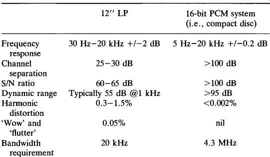
TBL. 5 Analogue versus digital performance characteristics
To illustrate the advantages of digitally encoded signal storage, a comparison between the performance of a good quality analogue recording , for example, a new (i.e., not previously played) 12 inch vinyl 'LP' disk, and a 16-bit digitally encoded equivalent is shown in TBL. 5.
There are, of course, some snags. Of these, the most immediate is the problem of 'editing' the digitally encoded signal on the tape. In the case of conventional analogue reel-to-reel tape machines, editing the tape to remove faults, or to replace unsatisfactory parts of the recording, is normally done by the recording engineer by inching the tape, manually, backwards and forwards across the general region of the necessary edit, while listening to the output signal, until the precise cut-in point is found.
A physical tape replacement is then made by 'cut and splice' techniques, using razor blade and adhesive tape.
Obviously, editing a digital tape is, by its nature, a much more difficult process than in the case of an analogue record, and this task demands some electronic assistance. A range of computer-aided editing systems has therefore been evolved for this purpose, of which the preferred technique, at least for '16-bit' 'stereo' recordings, is simply to transfer the whole signal on to a high capacity (1 Gbyte or larger) computer 'hard disk', when the edit can be done within the computer using an appropriate program.
The second difficulty is that the reproduced waveform is in the form of a 'staircase' (as shown in the simplified example shown in FIG. 34), and this is a characteristic which is inherent in the PCM process. The type of audible distortion which this introduces becomes worse as the signal level decreases, and is of a curious character, without a specific harmonic relationship to the fundamental waveform.
The PCM process also causes a 'granularity' in low level signals, most evident as a background noise, called 'quantization noise', due to the random allocation of bit level in signals where the instantaneous value falls equally between two possible digital steps. This kind of noise is always present with the signal and disappears when the signal stops: it differs in this way from the noise in an analogue recording, which is present all the time.
In normal PCM practice, a random 'dither' voltage, equal to half the magnitude of the step, is added to the recorded signal, and this increases the precision in voltage level resolution which is possible with signals whose duration is long enough to allow many successive samples to be taken at the same voltage level. When the output signal is then averaged, by post-decoder filtering, much greater subtlety of resolution is possible, and this degree of resolution is increased as the sampling frequency is raised.
This increase in the possible subtlety of resolution has led to the growing popularity of 'oversampling' techniques in the replay systems of 'CD' players (a process which is carried to its logical conclusion in the 256x oversampling 'bitstream' technique, equivalent to a 11.29 MHz sampling rate), although part of the acoustic benefit given by increasing the sampling rate is simply due to the removal of the need for the very steep-cut, 20 kHz, anti-aliasing output filters essential at the original 44.1 kHz sampling frequency. Such so-called 'brick wall' filters impair transient performance, and can lead to a 'hard' or 'over bright' treble quality.
Some critical listeners find, or claim to find, that the acoustic characteristics of 'digital' sound are objectionable. They are certainly clearly detect able at low encoding resolution levels, and remain so, though less conspicuously, as the resolution level is increased.
For example, if the listener is allowed to listen to a signal encoded at 8-bit resolution, and the digital resolution is then progressively increased, by stages, to 16-bits, the 'digital' character of the sound still remains noticeable, once the ear has been alerted to the particular nature of the defects in reproduced signal. This fault is made much less evident by modern improvements in replay systems.
Professional equipment So far as the commercial recording industry is concerned, the choice between analogue and digital tape recording has already been made, and recording systems based on digitally encoded signals have effectively superseded all their analogue equivalents.
The only exceptions to this trend are in small studios, where there may seem little justification for the relatively high cost of replacing existing analogue recording equipment, where this is of good quality and is still fully serviceable. This is particularly true for 'pop' music, which will, in any case, be 'mixed down' and extensively manipulated both before and after recording, by relatively low precision analogue circuitry.
Some contemporary professional digital tape recording systems can offer waveform sampling resolution as high as '20-bit' (1048576 possible signal steps), as compared with the '16-bit' encoding (65536 steps) used in the compact disc system. The potential advantages, at least for archive purposes, offered by using a larger number of steps in the digital 'staircase' are that it reduces the so-called 'granularity' of the reproduced sound, and it also reduces the amount of 'quantization noise' associated with the digital-analogue decoding process.
Unfortunately, in the present state of the art, part of the advantage of such high resolution recording will be lost to the listener since the bulk of such recordings will need to be capable of a transfer to compact disc, and , for this transfer, the resolution must be reduced once again to 16-bit, with the appropriate resolution enhancing sub-bit 'dither' added once more to the signal.
Some 'top of the range' professional fixed head multi-track reel-to-reel digital recorders can also provide on-tape cueing for location of edit points noted during recording, as well as tape identification, event timing and information on tape usage, shown on a built-in display system.
However, although multi-track fixed head recorders are used in some of the larger commercial studios, a substantial number of professional recording engineers still prefer the Sony 'U-matic' or ?630' processor, which is, effectively, a direct descendant of the original Sony TCM-G and
'PCM-FI' audio transfer systems, which were designed to permit '16-bit' digitally encoded audio signals to be recorded and reproduced by way of a standard rotary head video cassette recorder.
It’s unlikely that the situation in relation to digital recording will change significantly in the near future, except that the recording equipment will become somewhat less expensive and easier to use, with the possibility of semi-automatic editing based on 'real time' information recorded on the tape.
What does seem very likely is that variations of the 'near-instantaneous companding' (dynamic range compression and expansion) systems developed for domestic equipment will be employed to increase the economy in the use of tape, and enhance the apparent digital resolution of the less expensive professional machines.
Domestic equipment:
In an ideal world, the only constraints on the design and performance of audio equipment intended for domestic use would be the need to avoid too high a degree of complexity - the cost of which might limit its saleability - or the limitations due simply to the physical characteristics of the medium.
However, in reality, although the detailed design of equipment offered by a mass-market manufacturer will be influenced by his technical competence, the basic function of the equipment will be the outcome of deliberations based on the sales forecasts made by the marketing divisions of the companies concerned, and of the policy agreements made behind the closed doors of the trade confederations involved.
A good example of the way in which these forces operate is given by the present state of 'domestic' (i.e., non-professional) cassette recording technology. At the time of writing (1994), it’s apparent that the future for high-quality domestic tape recording systems lies, just as certainly as in the case of professional systems, in the use of some form of digitally encoded signal.
This is a situation which has been known, and for which the technical expertise has been available for at least 20 years, but progress has been virtually brought to a standstill by a combination of marketing uncertainties and objections from the record manufacturing companies.
As noted above, the major advantage offered by digital recording/ replay systems is that, in principle, an unlimited number of sequential copies can be made, without loss of quality - a situation which is not feasible with the 'analogue' process.
The realization that it’s now possible, by direct digital transfer of signals from a compact disc, to make a multiplicity of blemish free copies, indistinguishable from the original, has frightened the recording companies, who fear, quite reasonably, that this could reduce their existing large profits.
As a result, their trade organization, the International Federation of Phonograph Industries (IFPI) has pressed for some means of preventing this, at least so far as the domestic user is concerned, and has brought pressure to bear on their national governments to prevent importation of digital cassette recorders until the possibility of unlimited digital copying has been prevented.
This pressure effectively put a stop to the commercial development, ten years ago, of digital audio tape (DAT) machines, apart from such pioneering units as the Sony PCM-FI, which is designed for use with standard 1/2 inch rotary-head video tape recorders, and which were classified as 'professional' units.
A technical solution to the record manufacturers objections has now been developed, in the form of the 'Serial Copy Management System' (SCMS). On recorders fitted with this device, a digitally coded signal is automatically added to the 'first generation' tape copy, when this is made from a 'protected' source, such as a compact disc, and this will prevent any further, 'second generation', digital copies being made on an 'SCMS' equipped recorder. However, even if the copy is made from an unprotected source, such as a direct microphone input, a digital copy of this material will still carry a 'copy code' signal to prevent more than one further generation of sequential copies from being made.
In the interim period, the debate about the relative merits of domestic 'S-DAT' recorders (digital tape recorders using stationary head systems) and 'R-DAT' systems (those machines based on a rotary head system, of the kind used in video cassette recorders) had faded away. In its original form, 'S-DAT' is used solely on multiple track professional systems, and 'R-DAT' apparatus is offered, by companies such as Sony, Aiwa and Casio, mainly as portable recorder systems, which come complete with copy-code protection circuitry.
The success of any mass-market recording medium is dependent on the availability of pre-recorded music or other entertainment material, and because of the uncertainties during the pre-'SCMS' period, virtually no pre-recorded digital tapes (DAT) have been available, and now that the political problems associated with 'DAT' seem to have been resolved, three further, mutually competitive, non-professional recording systems have entered the field.
These are the recordable compact disc (CDR), which can be replayed on any standard CD player: the Sony 'Mini-Disc', which is smaller (3 in), and requires a special player: and the Philips 'Digital Compact Cassette' (DCC), which is a digital cassette recorder which is compatible with existing compact cassettes for replay purposes.
This latter equipment was developed as a result of a commercial prediction, by the Philips marketing division, that vinyl discs, especially 12 inch 'LP's, would no longer be manufactured beyond 1995, and that compact cassettes, at present the major popular recorded music medium, would reach a sales peak in the early 1990s, and would then begin to decline in sales volume, as users increasingly demanded 'CD' style replay quality.
Compact discs would continue their slow growth to the mid-1990s but sales of these would become static, from then onwards, mainly due to market saturation. What was judged to be needed was some simple and inexpensive apparatus which would play existing compact cassettes, but which would also allow digital recording and replay at a quality standard comparable with that of the compact disc.
The Philips answer to this perceived need is the digital compact cassette player, a machine which would accept, and replay, any standard compact cassette, and would therefore be 'backwards compatible' both with existing cassette stocks, and user libraries. However, when used as a recorder, the unit will both record and replay a digitally encoded signal, at the existing 4.76 cm/s tape speed, using a fixed eight-track head.
Unfortunately, digital recording systems are extravagant in their use of storage space, and the technical problems involved in trying to match the performance of a compact disc, and in then accommodating the digitally encoded signal on such a relatively low speed, narrow width tape, as that used in the compact cassette, are daunting. Even with the effective resolution reduced, on average, to the 4-bit level, a substantial reduction in bit rate is necessary from the 4.3218 Mbit/s of the compact disk to the 384 kbit/s possible with the digital compact cassette.
The technical solutions offered by Philips to this need for an eleven-fold bit-rate reduction are what is termed 'precision adaptive sub-band coding' (PASC), and 'adaptive bit allocation' ( ABA). The 'PASC system is based on the division of the incoming audio signal into 32 separate frequency 'sub-bands', and then comparing the magnitude of the signal in each of these channels with the total instantaneous peak signal level. The sub-band signals are then weighted according to their position in the frequency spectrum, and any which would not be audible are discarded.
The ' ABA' process takes into account the masking effect on any signal of the presence of louder signals at adjacent, especially somewhat lower, frequencies, and then discards any signals, even when they are above the theoretical audibility threshold, if they are judged to be likely to be masked by adjacent ones. The 'spare' bits produced by this 'gardening' exercise are then re-allocated to increase the resolution available for other parts of the signal.
Reports on demonstrations of the digital compact cassette system which have been given to representatives of the technical press, suggest that Philips' target of sound quality comparable with that of the compact disc has been achieved, and the promised commercial backing from the record companies leads to the expectation that pre-recorded cassettes will be available, at a price intermediate between that of the CD and the existing lower quality compact cassette.
Blank tapes, using a chromium dioxide coating, will be available, initially, in the 'C60' and 'C90' recording lengths, and are similar in size to existing analogue cassettes, but have an improved mechanical construction, to allow a greater degree of precision in tape positioning.
In the analogue field, improved cassette record/replay heads capable of a genuine 20 Hz-20 kHz frequency response are now available, though tape characteristics, even using metal tape, prevent this bandwidth being attained at greater signal levels than 10 dB below the maximum output level. There is a greater availability, in higher quality cassette recorders, of the HX-PRO bias control system, in which the HF signal components present in the incoming program material are automatically taken into account in determining the overall bias level setting. When this is used in association with the Dolby C noise reduction process s/n ratios better than 70 dB have been quoted.
A further improvement in performance on pre-recorded compact cassettes has been offered by Nakamichi by the use of their patented split-core replay head system, which is adjusted automatically in use to achieve the optimum azimuth alignment , for replaying tapes mastered on other recorders, and 'three-head' recording facilities are now standard in 'hi-fi' machines.
The extent to which manufacturers will continue to improve this medium is, however, critically dependent on the success, in the practical terms of performance, cost and reliability, of the digital compact cassette system.
Whatever else, the future for domestic equipment is not likely to be one of technical stagnation.