SERIES-CONNECTED DC-TO-DC CONVERTER
This circuit shows a series connected dc-to-dc converter using four power transistors type 2N 1100. In addition to the schematic diagram, there are three curves showing how voltage, frequency, and efficiency vary for three different ambient temperatures.
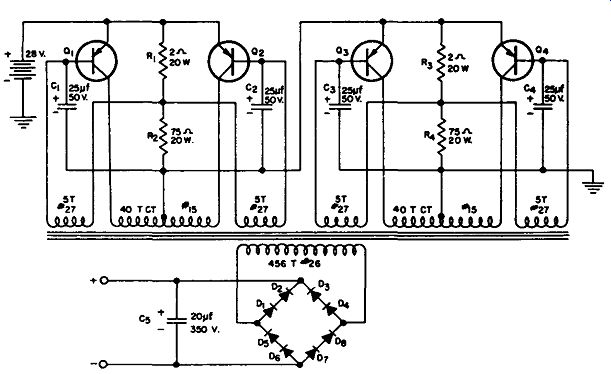
------------- Series-connected dc-to-dc converter.
R,, R, - 2g, 20W, wire wound resistor
R,, R. - 75g, 20W, wire wound resistor
C,, C,, C3 , c. - 25 mfd, 50V electrolytic capacitor
C, - 20 mfd, 350V electrolytic capacitor
D,, D., D,, D., D., D6 , D1 , D8-- Silicon diode (Sarkes Tarzian M500 or equivalent)
Q,, Q., Q,, Q. - 2N1100 Delco Hi-Power Transistor
T1-Transformer, core is Westinghouse RH-79 Toroid (or equivalent), primary and feed back windings are bifilar.
(A) Converter circuit.
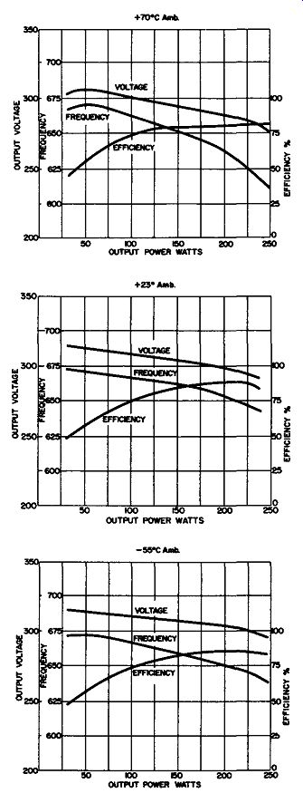
----------- (B) Voltage, frequency, and efficiency vs ambient temperature.
A series connection of transistors allows the operation of converter circuits such as this at higher supply voltages than would ordinarily be possible. All of the transformer windings must be on the same core in order to provide for proper phasing and equal power distribution so that the voltages applied to each transistor will be equal.
These transistors act as switches controlled by bias voltages; the bias voltage for each transistor is obtained from the feedback winding.
With no voltage induced in the feedback winding, resistors R1, R2, R3, and R4 ( as shown in the circuit) act as voltage dividers to provide enough forward bias to allow the beginning of conduction and oscillation. For explanation, assume that transistors Q1 and Q5 are conducting, while transistors Q2 and Q4 are not conducting; the supply voltage is thus divided to the left-hand half of each of the primary windings as shown. When transistors Q1 and Q3 begin to conduct, the current through these halves of the primary windings increases, and voltage is induced in all windings of the transformer; when saturation is reached, the induced voltage is decreased to zero. When the voltage induced in the feedback windings decreases and these two transistors are not saturated, the collector current decreases, causing the core flux to decrease. This decrease induces a voltage in the transformer windings of a polarity which is opposite to the original induced voltage. The voltage thus induced biases Q1 and Q3 to cutoff, while Q2 and Q4 are driven to saturation. Output voltage from the circuit is a square wave where the frequency and amplitude depend on the number of turns in the transformer, the supply voltage, and the flux density of the core material.
Resistors R1 through R4 help to start oscillation, capacitors C1 through C4 are used to protect the transistors, while all of the diodes used in the circuit are connected in a bridge, with two diodes in each bridge leg to provide full-wave rectification. With an output power of 175 watts, there is an output voltage of 300 volts at a 23 °C ambient temperature.
HIGH-VOLTAGE CONVERTER
This circuit shows a two-transistor converter that will change a 3-volt d-c input to a high-voltage a-c output. An output of up to 2100 volts ac can be obtained from this converter with this input voltage.
When switch SW1 is closed, the battery voltage appears across the primary of the transformer T1. The closed-loop path is completed by the leakage current to transistor Q2, and this voltage is then enough to drive transistor Q1 to the on condition, causing it to begin conduction.
When Q1 is turned on, it provides sufficient drive to turn on transistor Q2, and the primary voltage of transformer T1 will decrease in an exponential fashion. When the primary voltage drops below the required voltage to keep transistor Q1 on, this transistor turns off, the magnetic field of the transformer collapses, and this action induces a 60-volt field in the primary of T1. At the same time, this produces the necessary high voltage, which is about 2000 volts, in the secondary. At this time Q1 turns on again so that the cycle is repeated. Diode D1 is a protective diode; it is in the circuit so that the voltage of the primary is not impressed across the base-to-emitter junction of transistor Q1.
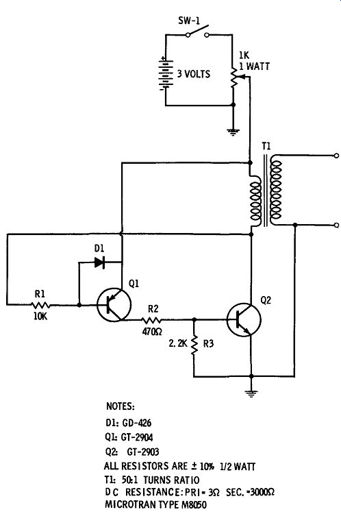
-------------- High-voltage converter.
NOTES: D1: GD-426 Q1: GT-2904 Q2: GT-2903 ALL RESISTORS ARE .± 10% 1/2 WATT Tl: 50:1 TURNS RATIO DC RESISTANCE:PR1•3Q SEC.•3000Q MICROTRAN TYPE M8050
225-WATT 10-Khz CONVERTER
This circuit shows two type 2N1936 transistors used in a dc-to-dc converter operating at 10 -khz. This circuit operates with an efficiency of 80% and an output ripple of less than 1 volt; it provides a 150 volt output from a 28-volt input source. This is a switching type of dc-to-dc converter. The power transistors and the diodes must have adequate heat sinks for proper operation.
NOTE:
Minimum usable hfE·10 at 10 amps, VcE • 3v. Both transistors use heat sinks, llcHS + ~S-A ~ 2 C/w each. All diodes must have adequate heat sinks.
Transformer data: Core· Arnold 2T-6847 - SI or equivalent Np • 15 turns 113 heavy Formvar NF· 6 turns, tapped at 3 turns 118 Ns • 87 turns 118
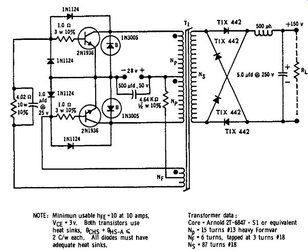
-------- 225-watt 10-khz converter.
DC-TO-DC CONVERTER
This is a 120-watt dc-to-dc converter using two type 2Nl 722 transistors in the switching circuit. Four 1Nl096 silicon-rectifier diodes are used in the bridge-circuit output to provide 400 volts at 120 watts. This converter circuit has an input current of 5 amperes and an output ripple of 0.6 volt maximum. The overall circuit efficiency is 85%.
This is a self-starting switching circuit where the conducting transistor builds up a magnetic field until saturation is reached, and the collapsing magnetic field turns the other transistor on. Both transistors are mounted on a dual-transistor heat sink.
NOTES:
1. All Resistance Values in ohms, 5% Tolerance.
2. All Resistor Wattage Ratings at 125°C Ambient.
3. Capacitor Voltage Ratings at 125°C Ambient.
4. Both Transistors on Same Heat Sink, 8c-Hs +8Hs-A 4 C0/w each.
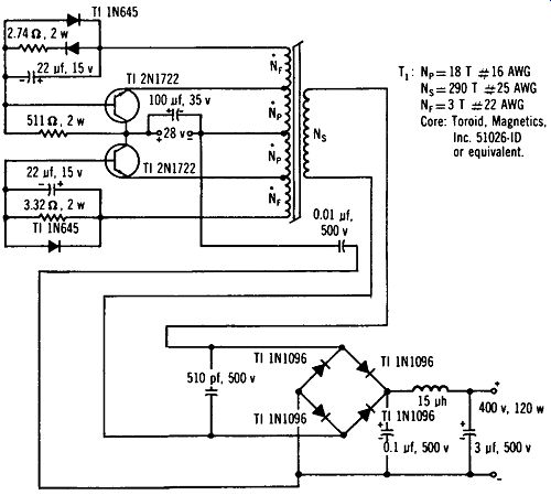
--------- Dc-to-dc converter.
145/225-WATT CONVERTER
This circuit shows a two-transistor power converter with an output of 145 watts with an input of 14 volts, and a power output of 225 watts with an input of 28 volts. Information on both of these applications is shown in the parts list.
This circuit, like many other converters, is essentially a power flip-flop where one transistor is conducting while the other is cut off.
The result is a square-wave output, and as shown in the circuit, operation is at about 800 cycles. Resistors R1 and R2 are used to start oscillation by biasing the transistors, while the four diodes form a bridge rectifier to produce the d-c output. Capacitive filtering is used to provide both a 150-volt and a 300-volt d-c output. It is necessary in this application that the transistors be mounted on heat sinks; a recommended heat sink is the Delco type 7276040. The total output current cannot exceed 750 milliamperes because of the rectifier diodes. The primary wire size can be changed to No. 13 for the 14-volt connector and to No. 15 on the 28-volt connector; this will result in a slight loss in efficiency.
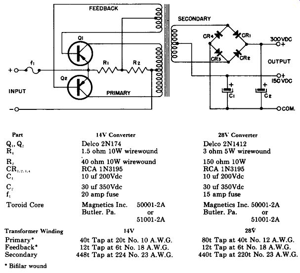
---------- 145/225-watt converter.
Part Q.,Q, R, C f, Toroid Core 14\' Condutor Delco 2Nl74 1.5 ohm 10W wirewound
40 ohm 10W wirewound RCA 1N3195 10 uf 200Vdc 30 uf 350Vdc 20 amp fuse Magnetics Inc. 50001-2A Butler. Pa. or 51001-2A 28\
Convener Delco 2Nl412 3 ohm 5W wirewound 150 ohm 10W RCA 1N3195 10 uf 200Vdc 30 uf 350Vdc 15 amp fuse Magnetics Inc. 50001-2A Butler. Pa. or 51001-2A
Transformer Winding Primary-Feedback Secondary
• Bifilar wound 14V 40t Tap at 20t No. 10 A.W.G. 12t Tap at 6t No. 18 A.W.G. 448t Tap at 224 No. 23 A.W.G. 28V 80t Tap at 40t No. 12 A.W.G. 12t Tap at 6t No. 18 A.W.G. 440t Tap at 220t No. 23 A.W.G.
DC-TO-DC CONVERTER
This is a common-collector circuit operating as a dc-to-dc converter to produce 100 watts at 400 cycles into the rectifier. Transistors type 2N443 are used with a 12-volt source, producing 500 volts of output to the load. Type SKM500 diodes are used as the rectifiers.
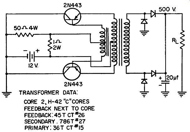
--------------- Dc-to-dc converter.
TRANSFORMER DATA: CORE 2, H-42 11 C11 CORES FEEDBACK NEXT TO CORE FEEDBACK:45T CT#26 SECONDARY.786T#27 PRIMARY: 36T CT#15
6-TO-12 VOLT DC-TO-DC CONVERTER WITHOUT RECTIFIERS
This circuit is a dc-to-dc converter that provides a 12-volt d-c out put using a 6-volt d-c source; the frequency of operation is 300 cycles.
A pair of 2N443 transistors is used as shown. The necessary voltage amplification or multiplication is obtained by means of adding the supply voltage to the feedback voltage. In operation, assume that transistor Q1 is turning on. Voltages will be generated with the polarities as shown in the schematic; thus a negative voltage is applied to the base of transistor Q1. Because of these polarities, there is a positive feedback, and transistor Q1 will conduct until the transformer is saturated. At this point there is about 6.8 volts across the upper half of the primary winding, which develops 8 volts in each half of the feedback winding. Voltage in the lower half of the feedback winding adds to the supply voltage to provide approximately 14 volts across the load.
Current path, as shown, is from the lower end of the feedback winding, through the emitter-to-base diode, to the positive end of the input voltage. Voltage in the feedback winding is thus added to the 6-volt source, and there is about 0.6- to 1-volt drop across this diode.
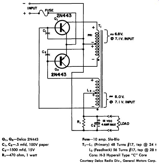
---------- 6-to-12 volt dc-to-dc converter.
Q1. Q2-Delco 2N443 c,. C2-.5 mfd, 100V paper Cs-1500 mfd, 15V 1 1-470 ohm, 1 watt FvM-1 0 amp. Slo-Blo T1-L1 (Primary) 48 Turns #17, tap @ 24 t L 2 (Feedback) 56 Turns #17, tap @ 28 t Core: H-3 Hypersil Type "C" Core
While Q1 is conducting, Q2 operates in this fashion; about 16 volts is available across the entire feedback winding and about 15 volts of this will appear as reverse bias for Q2. The reverse bias on Q2 is due to the forward conducting voltage of the emitter-to-base diode of Q1. When the transformer saturates, the magnetic field collapses and voltages of a polarity opposite to those shown are generated; Q1 is now cut off, and Q2 begins to conduct.
In this circuit the emitter-to-base diodes can be considered as rectifying diodes in a full-wave circuit, so the d-c output is taken from the center tap of the feedback winding. R1 is used to assist in the starting of oscillations, C1 and C2 are used for suppression of the spikes, and C3 is the filter capacitor.
Both transistors should be mounted on one Delco 7281352 heat sink.
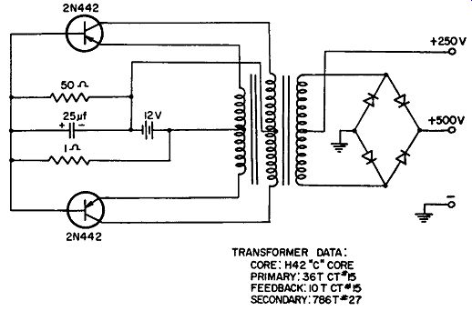
----------- Dc-to-dc converter.
TRANSFORMER DATA: CORE: H42 "C" CORE PRIMARY: .36T cT•l5 FEEDBACK: IOT CT"'l5 SECONDARY: 786T•27
DC-TO-DC CONVERTER
This circuit uses type 2N442 transistors and type SKM500 diodes.
This common-base circuit produces 100 watts of output power at 800 cycles into the rectifier. The original battery source is 12 volts, and the output is either 250 volts or 500 volts, as shown.
DC-TO-DC CONVERTER (30-VOLT TO 480-VOLT)
This is a power converter for changing a low d-c voltage to a high d-c voltage; the input is 30 volts, and the output is 480 volts at 250 ma.
Four power transistors are used. Each transistor has a feedback winding, with a 2-ohm resistor in series, from its emitter to base.
One transformer with four feedback windings is used, one winding for each power transistor. The primary winding has 200 turns and the output winding has 3470 turns. A bridge rectifier, with two diodes in series for each leg, is used to rectify the ac across the out put winding to produce the high d-c voltage.
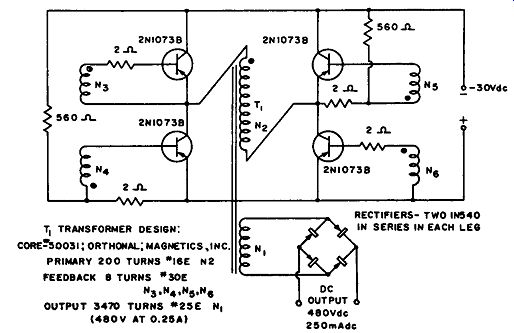
----------- Dc-to-dc converter.
---------------- Dc-to-dc converter.
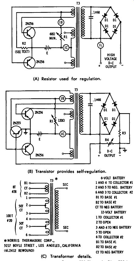
(A) Resistor used for regulation.
(B) Transistor provides self-regulation.
(C) Transformer details.
DC-TO-DC CONVERTERS
Two different dc-to-dc converters are shown using 2N256 transistors. The maximum switching ratings for these transistors are 2 amperes for each collector and 100 ma for each base. Meters are shown so that these readings can be monitored, since various input voltages can be used. The output voltages obtained with these two circuits depend on the input voltage used; a range of 2- to 350-volts d-c output can be obtained for input voltages of 6 to 12 volts.
In the circuit shown in Fig. A, forward bias is used to make sure that the circuit begins to oscillate. Resistor R2 is used for regulation.
The value of this resistor should be about ten times the resistance of R1, and the value of R1 depends on the applied d-c input voltage.
In Fig. B a 2N255 transistor is used in place of R2 to provide for self-regulation. In this circuit, resistor R3 should be about 5% of the load resistance, and the value of R4 is chosen to provide for the required output voltage for the particular application. The rectifier diodes that are used in either circuit depend on the voltage available across the secondary, which in turn depends on the input voltage.
Typical rectifiers are the 1N1764 which has a voltage rating of 500 volts at an average forward current of 0.5 ampere, and the 1N3256 which has a maximum voltage of 800 volts and has the same current rating as the 1N1764. Other suggested rectifiers with a forward cur rent rating of 0.75 ampere are the 1N3253 for 200 volts, the 1N3254 for 400 volts, or the 1N3255 for 600 volts.
Fig. C shows the suggested transformer as used in these two converters. Details of the transformer used and the model number are shown.
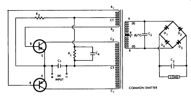
DC-TO-DC CONVERTER
This circuit shows a dc-to-dc converter with suggested transistor types 2N1358, 2N1100, 2N443, and 2N174. The suggested rectifiers are types 1N1763, 1N1764, IN3196, and 1N3256.
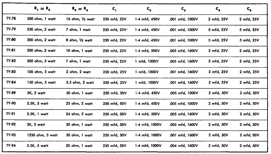
Various types of transformers can provide different types of voltage output. For Triad transformers TY78 through TY84 the input is 12.6 volts d-c. Two voltage outputs can be obtained, depending upon whether the circuit is connected as a full-wave bridge as shown, in which case the higher output voltage is produced, or whether the circuit is connected as a full-wave center tap, in which case the lower output voltage is available. For the TY78 transformer the output voltage is 250 volts or 125 volts, at 100 ma. For the TY79 transformer the output is 300 or 150 volts, at 200 ma. For the TY80 transformer the output is 325 or 162.5 volts, at 150 ma. For the TY81 transformer the output is 375 or 187.5 volts, at 200 ma. For the TY82 transformer the output is 450 or 225 volts, at 150 ma.
For the TY83 transformer the output is 500 volts or 250 volts, at 250 ma. For the TY84 transformer the output is 600 or 300 volts, at 200 ma.
-------
Parts List
For a 28-volt d-c input other transformer types are available as shown. These are Triad types TY89 through TY94. For transformer type TY89 the output is 300 or 150 volts, at 100 ma. For type TY90 the output is 325 or 162.5 volts, at 200 ma. For type TY91 the out put is 375 or 187.5 volts DC, at 200 ma. For type TY92 the output is 450 or 225 volts, at 200 ma. For type TY93 the output is 500 or 250 volts, at 250 ma. For type TY94 the output is 600 or 300 volts DC, at 200 ma.
-------------- Dc-to-dc converter.
DC-TO-DC CONVERTER
This circuit shows a common-emitter dc-to-dc converter with suggested transistor types 2N173, 2N174, 2N443, 2N1100, or 2N1358.
Rectifier types that are suggested are 1N1764 and 1N3196.
Two different voltage outputs are available, depending on whether the circuit is connected in a full-wave bridge configuration where the higher output is available, or connected as a full-wave center tap where the lower voltage output is obtained.
Triad transformers type TY78 through TY86 are available for use with a 12.6-volt DC input. Various voltage outputs are available with the different transformers. For transformer TY-78, 250 or 125 volts at 100 ma is available. For type TY79, 300 or 150 volts DC at 200 ma is available. For type TY80, 325 or 162.5 volts at 150 ma is avail able. For type TY-81, 375 or 187.5 volts DC at 200 ma can be obtained. For type TY-82, 450 or 225 volts at 150 ma can be obtained.
For type TY-83, 500 or 250 volts at 250 ma can be obtained. For type TY-84, 600 or 300 volts at 200 ma can be obtained. For type TY-85, 600 or 300 volts at 350 ma can be obtained. For type TY-86, 425 or 212.5 volts DC at 350 ma can be obtained.
For a 28-volt d-c input various other transformers are available, as indicated. For type TY-89, 300 or 150 volts DC at 100 ma can be obtained. For type TY-90, 325 or 162.5 volts DC at 200 ma can be obtained. For type TY-91, 375 or 187.5 volts at 200 ma can be obtained. For type TY-92, 450 or 225 volts at 200 ma can be obtained.
For type TY-93, 500 or 250 volts DC at 250 ma can be obtained. For type TY-94, 600 or 300 volts at 200 ma can be obtained.
There are also other voltage outputs available by using a 6.3-volt input in place of the two voltage inputs just given. Using a transformer type TY-99, an output of 300 or 150 volts at 100 ma can be obtained. Using transformer type TY-100, an output of 325 or 162.5 volts at 150 ma can be obtained. Using transformer type TY 101, an output of 375 or 187.5 volts at 200 ma can be obtained. Using transformer type TY-102, an output of 450 or 225 volts at 150 ma can be obtained.
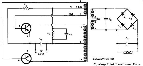
-------------- Common-emitter dc-to-dc converter.
------------ Dc-to-dc converter.
DC-TO-DC CONVERTER
This circuit shows several possible dc-to-dc converter arrangements using transistor types 2N1 73, 2N174, or 2N443, and rectifier types 1N1763, 1N1764, or 1N3256. In each case the input is 12.6 volts DC.
In this common-emitter circuit three different Triad transformers are suggested for three different output ranges. For transformer type TY68S the output is 250 volts using a full-wave bridge rectifier, and 125 volts using a full-wave center tap; in both cases the current maxi mum is 65 ma. With transformer type TY70S the output is either 325 or 162.5 volts DC at 150 ma. Using transformer type TY-71S the output is 375 or 187.5 volts DC at 200 ma.
DC-TO-DC CONVERTER
This is a common-emitter type of dc-to-dc converter using type 2N441 transistors and type SKM500 diodes. The input to the converter is a 6-volt battery, and the input into the rectifier is 50 watts at 400 cycles. The circuit has an output of 250 volts.
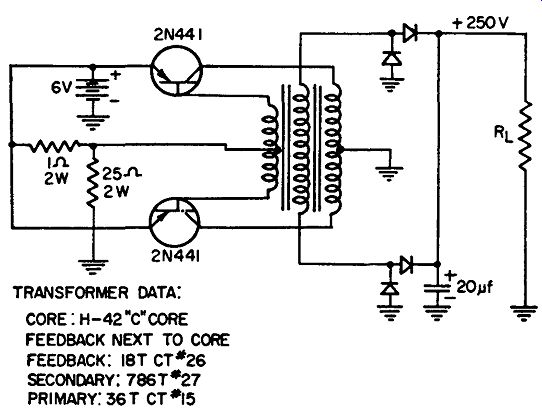
------------ Common-emitter dc-to-dc converter.
DC-TO-DC CONVERTER
This is a dc-to-dc converter or voltage multiplier that can step up a small d-c voltage to a large d-c voltage. Since various voltage step ups are possible, the circuit as shown has three meters, one for measuring the base current, one for the emitter current, and one for the output current.
For the transistors shown, the maximum switching rating is 2 amperes for each collector and 100 ma for each base. A control is adjusted to provide currents within these ranges for the specific voltage used for the input.
Suggested transformers for a voltage step-up from 6 volts to 250 volts are shown; other transformers can be used provided that the same current ratio is maintained.
T1 turns ratio is E;uT + E1N; for an EouT of 250 volts DC and an E1N of 6 volts DC, a filament transformer (115 volts/6 volts C.T.) can be used if its power rating is at least equal to the power output. T2 is a tube-to-voice-coil transformer of 2000/8-4 ohms impedance. D-1 can be a 1N1763 or 1N443B.
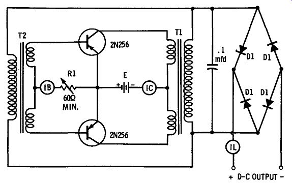
----------------- Converter or voltage multiplier.
DC-TO-DC CONVERTER
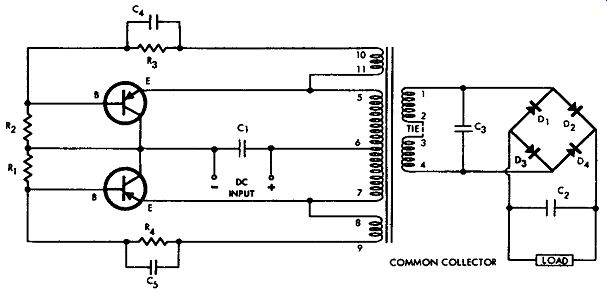
Two circuits are shown for dc-to-dc conversion. Fig. A is a common-emitter circuit, while Fig. B is a common-collector circuit.
Figs. A and B both use Triad TY88 transformers. The supply voltage is 28 volts DC, and if it is connected as a full-wave bridge circuit, the output voltage is 250 volts DC. If the input is connected as a full-wave center-tap rectifier, the output voltage would be half this value, or 125 volts DC. The maximum current drain is 80 ma.
The suggested transistors are type 2Nl 73, 2Nl 74, 2N443, or 2N1099.
Suggested rectifiers are 1N1763, 1N1764, 1N3196, or IN3256.
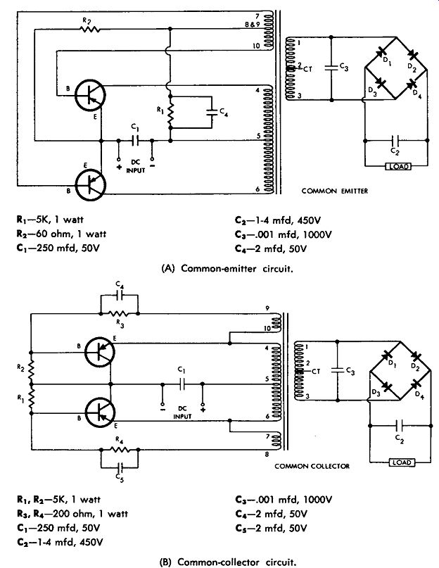
------------------ Dc-to-dc converter circuits.
(A) Common-emitter circuit.
R1 -5K, 1 watt R,-60 ohm, 1 watt C1-250 mfd, 50V C2- l-4 mfd, 450V C3-.001 mfd, 1000V C4 -2 mfd, 50V
(B) Common-collector circuit.
R1, R2-5K, 1 watt
R3, R,-200 ohm, 1 watt
C1-250 mfd, 50V
C2 -1-4 mfd, 450V
C3-.001 mfd, 1000V
C4-2 mfd, 50V
C5-2 mfd, 50V
DC-TO-DC CONVERTER
This is a common-emitter type of dc-to-dc converter using 2N442 transistors. This circuit produces 100 watts of 800-cycle power into the rectifier, which uses four type SKM500 diodes. The input power supply is 12 volts, and the output of the converter is at two levels: +250 volts and +500 volts.
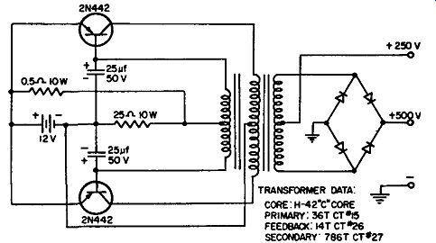
------------- Dc-to-dc converter.
DC-TO-DC CONVERTER
This circuit shows two 2N441 transistors operating as a common collector dc-to-dc converter from 6 volts to 250 volts. All diodes are type SKM500, and the circuit provides 50 watts output at 400 cycles into the rectifier circuit.
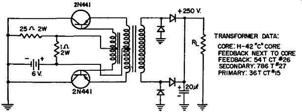
--------------- Dc-to-dc converter.