DC-TO-AC INVERTER
This circuit shows a dc-to-ac inverter using type 2N1073B transistors with fast switching times. The switching frequency of this circuit is about 2500 cycles; it is possible to add other secondary windings on the core or to add a high-voltage secondary if desired.
The output from this circuit can be fed into a half-wave or bridge rectifier in order to produce d-c output from the 150-volt peak out put at 120 watts.
Assume that Q1 starts conducting because of the negative-feedback voltage. The return path for the feedback voltage is through resistor R1 and through diode CR2. There is a voltage drop across CR2 when it is conducting, and this voltage is of such polarity that a reverse bias is fed to the emitter-to-base diode of Q2.This means that transistor Q2 is cut off while transistor Q1 is going into saturation. When the core saturates, the magnetic field begins to collapse and the polarity of the feedback voltage reverses. Q2 now starts to conduct, and Q1 is cut off. Now the feedback return is through diode CR1 and the same action occurs as when Q1 was conducting. The voltage drop across CR1 will assure that Q1 is reverse biased, and therefore cut off.
Capacitors C1 and C2 are used to remove the spikes from the collector-to-emitter waveform. The reverse bias on the emitter diode never is greater than the voltage across CR1 and CR2, thus the emitter diodes are protected.
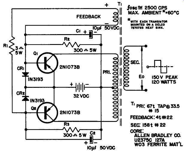
----- Dc-to-ac inverter.
HIGH-CURRENT INVERTER
The circuit in Fig. A shows a pair of 2N2728 power transistors operating in a low-voltage high-current inverter circuit. This inverter will change a 2-volt d-c source to a higher-voltage square wave. The circuit operates in a common-emitter arrangement. The secondary windings of the driver transformers are split to allow each transistor to be driven separately. Resistors R1 through R4 are used to provide a voltage divider and starting bias for the circuit. Fig. B shows the transformer specifications.
This inverter operates at about 1000 cycles per second with an efficiency of about 70%; the power output is 60 watts.
(A) Circuit diagram.
(B) Transformer specifications.
R1-0.75 ohm, 5 watt R2-0.75 ohm, 5 watt R3 -7.5 ohm, 5 watt R,-7.5 ohm, 5 watt RFa-1 ohm, 5 watt Ci-20 mfd, 6V C2-l0,000 mfd, 6V c,-20 mfd, 6V T1-Phoenix Transformer PX 2127 T2-Phoenix Transformer PX 2126
Q1, Q2-2N2728 V,.-2V, 50A
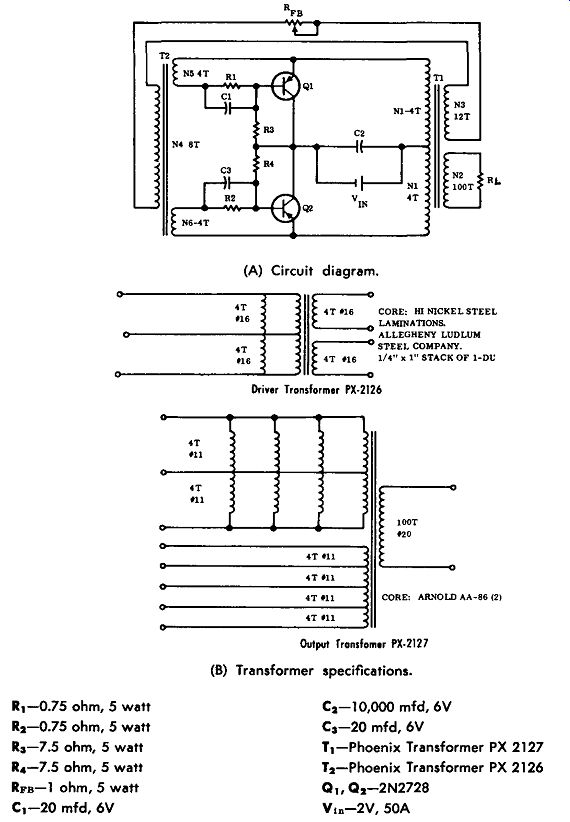
------------- High-current inverter.
DC-TO-AC INVERTER
This circuit shows an inverter with several voltage inputs and outputs. The suggested transistors are 2N1 73, 2N1 74, or 2N443.
Suggested rectifiers are 1N1763, 1N3196, or 1N3256.
With Triad transformer TY462, the input voltage is 12.6 volts DC; the output of 60 watts at 400 cycles is either at 110, 115, or 125 volts, depending on which transformer tap is used. With Triad transformer TY 468, a 28-volt input is used, and the same voltage outputs are available. In either case, the other circuit components are the same.
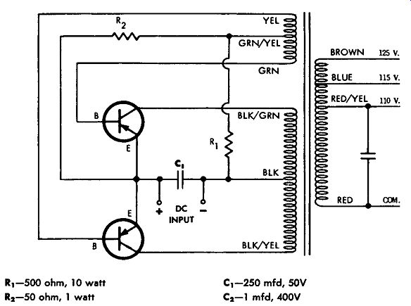
------------ Dc-to-ac inverter.
R1-500 ohm, 10 watt R2-50 ohm, 1 watt C1-250 mfd, 50V C2- 1 mfd, 400V
2-VOLT DC TO 120-VOLT AC INVERTER
This circuit shows an unusual inverter which produces 120 volts ac from a 2-volt d-c input. Transistors type 2N1518, 2N1519, 2N1520, 2N1521, 2N1522, and 2Nl523 can be used in this circuit since these transistors can switch anywhere from 25 to 50 amperes.
If the 2-volt d-c source has a current capability of 25 to 50 amperes, this circuit can deliver 30 to 50 watts of 120-cycle square-wave a-c output.
Only one bias resistor is used and a separate feedback transformer is not required. The circuit shows a 25-ampere 2-volt d-c inverter.
It is possible, by changing the bias resistor and size of the wire in the windings, to operate this circuit up to 50 amperes with a 2-volt d-c input. With the parts values shown in the circuit, type 2N1518 transistors are suggested.
In operation assume that Q1 begins to conduct, which increases the voltage drop across the primary of the transformer. This increasing voltage is coupled to the feedback winding, and a negative voltage is applied to the base of Q2, causing it to increase its conduction. Q1 causes the transformer to go into saturation, and the voltage across the primary collapses, causing a change in polarity which is coupled to the feedback winding. The feedback winding applies a reverse bias to 01 and a forward bias to Q2 so that there now is a reverse operation, with increasing conduction through Q2. Bias current is applied across R1. This circuit operates best with a d-c input of 3 volts or less.
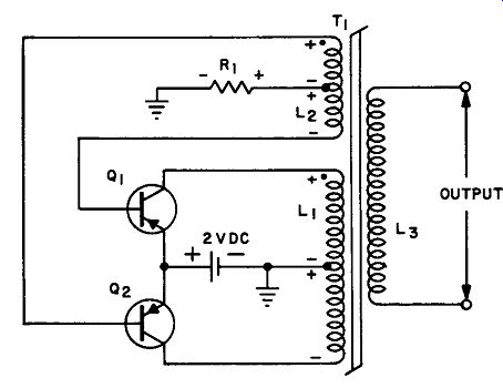
-------------- 2-volt dc-to-ac inverter.
R1-7.5 ohm in parallel with I ohm = .88 ohm, 10 watt T1-L1 (Primary) 30 turns No. 10, tap at 15 T L 2 (Feedback) 38 turns No. 19, tap at 19 T L 3 (Secondary) 1170 turns
No. 26 Core: Magnetics Inc. 51001-2A, Toroid.
Primary and feedback windings are bifilar.
110-VOLT INVERTER
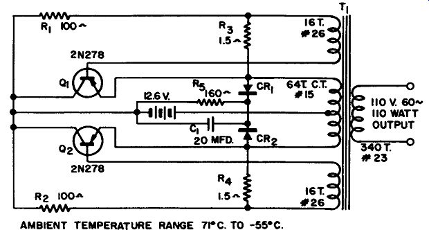
This circuit shows a dc-to-ac inverter that produces 110 watts of 110-volt 60-cycle output from a 12.6-volt input. In this circuit the transistors operate as switches, with one being off while the other is on.
Assume for the sake of operation that Q1 is on and Q2 is off, thus connecting the 12.6-volt battery supply across the top half of the center-tap primary winding. When transistor Q1 begins to conduct, there is a current flow through the transformer. A saturation of the core causes a collapse of the magnetic field and a switching of the transistor positions.
In this circuit resistors R1 through R4 are used to start the oscillations, while resistor R5, capacitor C1 and diodes CR1 and CR2 are used to provide a de-spiking network to protect the transistors. The suggested heat sink is given in the parts list for this unit.
--------------- 110-volt inverter.
R,. R2-100 ohm, 5 watt wirewound R,, R,-1.5 ohm, 5 watt, wirewound Rs-150 ohm, 5 watt, wirewound CR,. CR2-Power diode, Sarkes Tarzian M 500 or equivalent C1-20 mfd, 50V electrolytic Q1 , Q2-2N278 Delco power transistor T1-transformer: core-1 5/16" stack of 125 E.I. 0.014" silicon iron Heat sink-aluminum, 80 sq. in., finned.
The thermal resistance of this sink should be better than 2.1 °C/watt. This will permit operation in ambient temperatures up to 71 °C.
POWER INVERTER
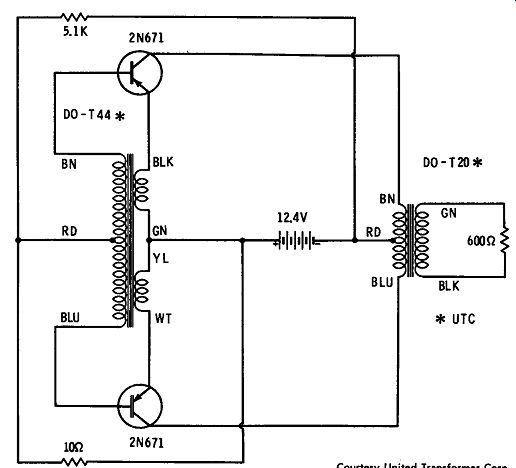
This circuit shows a power inverter operating from a 12-volt source and using two 2N671 transistors to produce a power output of ½ watt at a frequency of 1380 cycles per second. As shown, the power output is obtained across a 600-ohm load.
------------- Power inverter.
DC-TO-AC INVERTER
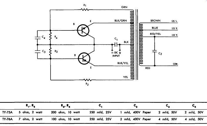
A dc-to-ac inverter using two different transformer types (Triad TY75A or TY76A) is shown. Suggested rectifiers are 1N1763, 1N1764, 1N3196, and 1N3256. Suggested transistors are 2N173, 2N174, 2N443, and 2N1099.
As shown in the circuit, with either transformer the input is 12.6 volts DC. For the TY75A, the output is 115 watts at 60 cycles with
-------- Dc-to-ac inverter.
------- High-frequency inverter.
(A) Circuit diagram.
(B) Transformer specifications.
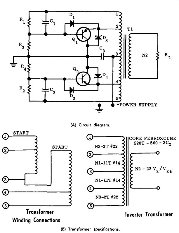
R1, R2-27 ohm, 1 watt Rs, R,.-2.2K, 2 watt C1 , C2 -0.5 mfd, 10V C5-250 mfd, 50V D1, D2- 1N4001 D5, D,.-1 N3039 B Q,, O2-2N2B33 T1 -See Fig. B Power Supply-28V dc, 5 amperes for 100 watts out
HIGH-FREQUENCY INVERTER
A pair of 2N2833 transistors operating in a high-frequency inverter circuit convert 28 volts DC to a 15-khz square wave as shown in Fig. A. Resistors R1 and R3, as well as R2 and R4, form voltage dividers which provide 0.35 volt of base voltage necessary to start the circuit.
Resistors R1 and R2 limit the base current once oscillation has started.
Diodes D1 and D2 are used in this circuit as emitter-base clamping diodes which are necessary to prevent reverse bias of the emitter-to base junction beyond the rating of the 2N2833 transistors. Zener diodes D3 and D4 are used to keep the collector-to-emitter voltage of the transistors at a proper level. Capacitor Ca is used to eliminate the lead inductance of the power-supply leads. The inverter uses a core which is a Ferroxcube 528T-500-3C2; the primary has 11 turns of the No. 14 wire and the feedback winding has 2 turns.
Fig. B shows the inverter transformer and its winding connections.