| Home | Audio mag. | Stereo Review mag. | High Fidelity mag. | AE/AA mag. |
The functions associated with both the recording and playback processes are, in most tape recording equipment, fulfilled by a single amplifier with suitable switching facilities. It is only with a few of the more elaborate and costly items of equipment that separate recording and playback amplifiers are used.
The circuit to be described in this section combines the requirements of both processes, and it can be used with many of the tape decks that are fitted with a combined record-playback head and a separate erase head. With such a deck, the amplifier forms a self-contained recording and reproducing unit which is capable of an excellent performance, whether it is reproducing recordings made on the same unit, or whether pre-recorded tapes are used.
Any tape amplifier must, if an acceptable performance is to be achieved, provide compensation for the unequal response over the audio-frequency range that is inherent in the process of magnetic recording. In keeping with general practice, the treble equalization is associated with the recording channel and the bass equalization is incorporated during playback.
It has been pointed out in Section 2 that the extent of treble attenuation is dependent on the tape speed.
It is thus desirable to provide separate high-frequency correction for the different tape speeds. In this amplifier, equalization is provided for speeds of 3 3/4, 7 1/2 and 15 inches per second.
In addition to the basic equalization, some measure of tone control may be desired in a complete recorder. Equalization is arranged to provide a level overall frequency characteristic. The tone control provided allows for modifications to be made to the playback characteristic so that the treble response can be attenuated to suit the demands of the individual listener. The control gives 12dB of cut at 10KHz.
The quality of the performance of the complete equipment is necessarily limited by the output stage of the playback system. A higher standard of reproduction can be achieved if a good-quality amplifier and pre-amplifier are fed from the low-level output of the playback amplifier.
Excluding the limitations mentioned in the previous paragraph, and the distortion introduced by the tape itself, the major source of distortion in this unit occurs in the recording stage. The operating conditions for the second section of the ECC83 are chosen as a compromise between the requirements of gain and output voltage and the desirability of maintaining a high a.c./d.c. load ratio. The voltage required from this stage to provide a recording current of 200µA depends on the series resistance between the anode and the recording head. A low value for this resistance, whilst reducing the output-voltage requirements, also increases the distortion of this stage. The total harmonic distortion in the recording stage at the peak level of 20V which has been adopted in this design is not more than 2% at 1-KHz.
--------------
------------
-------------
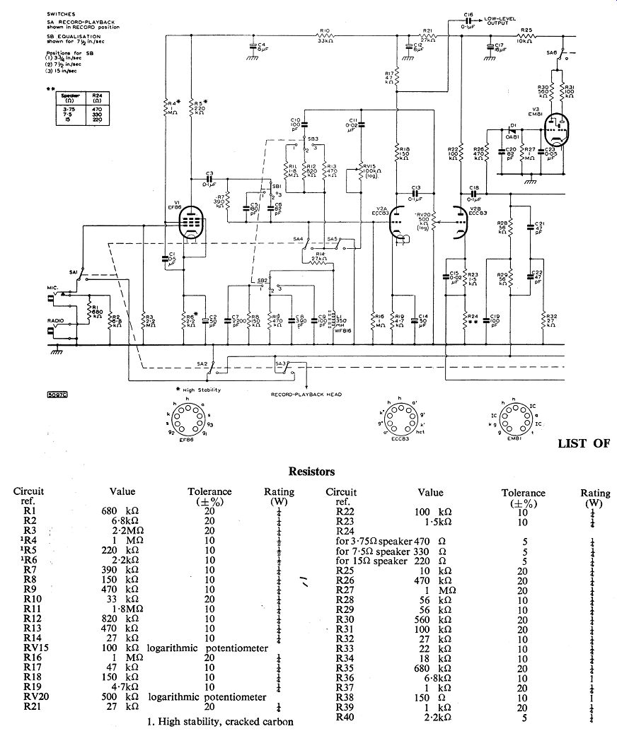

Fig. 1
CIRCUIT DESCRIPTION
The circuit diagram of the combined record-playback amplifier is given in Fig. 1.
Three stages of the circuit are common to both recording and playback processes. A fourth stage acts as an r.f. oscillator for the biasing and erasing signals when recording, and is used as an audio-output stage in the playback process. A subsidiary stage of the recording amplifier, which is excluded from the playback circuit, is the recording-level indicator stage.
Controls
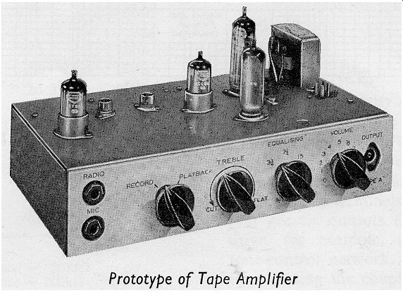
Four controls are provided in the circuit
(1) The switch SA sets the amplifier for either the recording or playback condition.
(2) The switch SB gives the appropriate equalization for a tape speed of either 15, 7 1/2 or 3 3/4 inches per second. The switch must be in the correct position during playback as well as when recording.
(3) The tone control RV15, which is operative only during playback, is situated in the anode circuit of the first section of the ECC83, and gives variable treble cut.
(4) The gain control RV20 operates during both recording and playback processes. It does not influence the low-level output which is available at the anode of the second stage of the amplifier.
Valve (tube) Complement
The amplifier uses four Mullard valve (tube) s and one Mullard germanium diode. These are
(a) Type EF86, low-noise pentode, used in the input stage for both recording and playback functions.
(b) Type ECC83, double triode. The first section of the valve (tube) is used in the equalizer stage for recording and playback. The second section is used as the output stage when recording and as a voltage amplifying stage during playback.
(c) Type EL84, output pentode. When recording, this is used as the oscillator valve (tube) , and in the playback process, it is used in a single-ended audio-output stage to drive the loudspeaker.
(d) Type EM 81, tuning indicator, used in the recording-level stage.
(e) Type OA81, germanium diode, used as the indicator-circuit rectifier.
Input Stage
The pentode, type EF86, acts as a voltage amplifier for both recording and playback processes. It is possible to record from either microphone or radio sources. Both inputs are fed to the grid of the valve (tube) , the radio being attenuated to the level of the microphone input.
The switching is achieved by inserting the jacks so that only one input may be used at a time.
Equalizer Stage
One section of the double triode, type ECC83, is used in the second or equalizer stage of both processes. The tone control which is operative only during playback, is also located in this stage.
During the recording process, a resonant circuit, containing a Ferroxcube pot-core inductor L1 is used to provide treble equalization. The value of tuning capacitance in the resonant circuit is selected by the equalization switch SB to give maximum treble boost appropriate to the particular tape speed. The degree of boost is controlled by the resistor R7 and the damping resistors R8 and R9 connected in parallel at SB2 with the capacitors C7 and C8. The steep fall in boost that occurs below the resonant frequency is modified by damping the inductor and by partially shunting R7 at SB1 at the appropriate frequencies.
The treble boost obtained will be correct for many combinations of tape and head, but it may be too great for others. If this is so, the damping on L1 should be increased by connecting a resistor in parallel with C9 and reducing the values of R8 and R9. The optimum values should be determined by listening tests.
During playback, the correct feedback for bass equalization is provided by the resistors R11, R12 and R13 arranged on SB3.
A low-level output of 250mV, having a source impedance of 50k-o, can be taken from the anode load of this stage of the amplifier and can be used either during recording for monitoring purposes, or during playback for feeding an external pre-amplifier and power amplifier.
Recording Output Stage
The output from the anode of the equalizer stage is taken to the grid of the second section of the double triode by way of the gain control RV20. Further high-frequency boost is added to the recording signal by the capacitor C15 in combination with the resistor R23.
The recording signal from the anode of the second section of the ECC83 is taken by way of a parallel-T network to the recording head.
The network presents its highest impedance at the biasing frequency.
Bias is fed to the recording head immediately after the T-network.
This arrangement produces a substantially constant current drive to the recording head and provides efficient rejection of the bias voltage at the anode of the output valve (tube) .
H.F. Oscillator (Record) or Power Output Stage (Playback)
The output pentode, type EL84, acts as an audio output stage during playback. In the recording process, the EL84 is used to provide the h.f. oscillations for the biasing and erasing signals.
The bias signal is introduced into the recording head through the capacitor C24, the value of which determines the bias current flowing in the head. The bias voltage is obtained from the anode of the EL84.
The oscillator coil and the choice of component values for the oscillator circuit will depend on the types of record-playback and erase heads used. The details given with Fig. 1 are those suitable for record-playback heads having an impedance between 15 and 30k-oand erase heads with an impedance between 200 and 300 ohm. Details for heads with other values of impedance should be obtained from the manufacturer of the tape deck used.
The bias oscillator coil and the primary winding of the output transformer are arranged in series. The latter is bypassed by the switch SA8 when in the recording position.
The presence of the capacitor C25 prevents an abrupt cessation of the oscillations when the amplifier is switched from the recording to the playback condition, and thus prevents magnetization of the record playback head. The erase head is earthed for the playback process by the switch SA9.
----------- Fig. 2
On playback, approximately 10dB of negative feedback is used, the feedback voltage being taken from the secondary winding of the output transformer to the cathode of the second section of the double triode. The harmonic distortion in the output stage is not more than 3% at 1KHz for an output level of 3W. The output power from the playback amplifier is fed by way of the transformer T1 to either a 3.75, 7.5 or 15 ohm speaker.
Recording-level Indicator
A tuning indicator, type EM81, is fed from the anode of the second section of the ECC83 through a detector circuit using a germanium diode, type OA81.
The value of the resistor R31 in the target-anode circuit governs the sensitivity of the indicator, and has been chosen to give a sufficiently high sensitivity to allow a large series resistance R26 to be used between the diode and the second anode of the ECC83. This large resistance minimizes the loading effect on the recording output stage.
The operating conditions of the EM81 are normally chosen so that the target shadow ‘closes' for a recording current of 200µA. They can however be chosen so that the shadow ‘closes' at lower peak recording levels if reduced peak distortion is desired at the expense of the signal-to-noise ratio.
In the playback position, switch SA6 disconnects the recording-level indicator stage from the h.t. supply, and this gives a positive indication of the position of the record-playback switch SA.
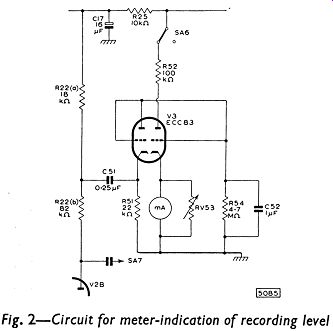
If a meter indication of the recording level is required, the EM81 stage of Fig. 1 can be replaced by the circuit given in Fig. 2. The valve (tube) used is an ECC83. The signal is taken from a point in the anode load R22 of the recording output stage (V2B in Fig. l), and the milliammeter (1mA, full-scale deflection) is included in the cathode circuit of the second half of the ECC83 of Fig. 2. The variable resistor RV53 should be chosen to suit the resistance of the milliammeter.
CONSTRUCTION AND ASSEMBLY
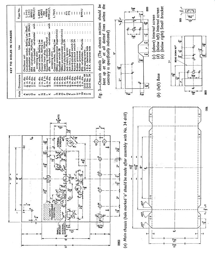
The chassis is made up of five separate pieces of 16 s.w.g. aluminum sheet. The dimensions (in inches) of these are (a) Main chassis 11 x 11 (b) Base 15 3/4 x 6 5/8 (c) Internal screen 9 x 2 3/8 (d) Internal screen 7 x 2 3/8 (e) Small bracket 1 1/4 x 1/2
Each piece should be marked as shown in the chassis drawings of Fig. 3, and the holes should be cut as indicated. It is important that, when bending the sheet, the scribed lines should be exactly along the angles. This ensures that the pieces will fit together properly when assembled.
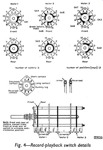
Before assembling the record-playback switch SA around the screens, it will probably be found convenient to fix the following components to the chassis:
(1) The erase and playback sockets which have to be fitted to the chassis beneath wafer 3 of switch SA. (2) The nylon-loaded valve (tube) holder for the ECC83, complete with the skirt for the screening can. Pins 1 and 9 should face towards the coaxial sockets.
(3) A five-way tagboard. This should be bolted to the internal screen (c) in the position marked ‘Tagboard No. 6' in the layout diagram of Fig. 11.
(4) The small fixing bracket (f), which should be bolted to the screen (c) as indicated in Fig. 3(a).
The construction is best continued by assembling wafers 1 and 2 of switch SA around the internal screen (d). The wafers should be arranged so that positions 6 and 7 are nearest the chassis and the face of each wafer described as the ‘rear' in the switch diagram (Fig. 4) is farthest from the switch plate. The internal screen (c) should be added to the assembly, both screens should be bolted together, and wafer 3 should be fitted in position, again with its ‘rear' face (Fig. 4) farthest from the switch plate. The general arrangement of the switch wafers and internal screens is shown in Fig. 11. Details of spacers required for the assembly are shown in Fig. 4. The use of a shock-proof washer is recommended between the switch plate and the front panel when the switch and screens are fitted to the main chassis. A suitable layout of the other components is shown in Fig. 11. The arrangements of the small components on tagboards are shown in Figs. 5 to 10.
Details of the equalizer switch are given in Fig. 12.
Frequency Response
Treble boost is incorporated during recording and bass boost during playback. Separate equalization is provided for tape speeds of 15, 7 1/2 or 3 3/4 inches per second to give the following attainable overall response (relative to the level at 1-KHz):
15 in./sec: ±3dB from 35Hz to 17KHz 7 1/2 in./sec: ±3dB from 50Hz to 13KHz 3 3/4 in./sec: ±3dB from 50Hz to 6KHz
The overall response at the higher frequencies depends on the type of head used and on the magnitude of the bias current. The response figures given above and the curves drawn in Fig. 13 will normally be obtained with a bias current of 0.5 to 1.0mA through heads of medium impedance.
--------------- Fig. 3
The playback characteristic of the amplifier at a tape speed of 7 1/2 inches per second is designed to the C.C.I.R. specification, thus permitting excellent reproduction of pre-recorded tapes. The recording characteristic is arranged to give a flat frequency response in conjunction with this replay characteristic.
Sensitivity
The sensitivity of each amplifier is measured with the control RV20 set for maximum gain. This, of course, does not apply to the low-level output measurements: the control is not effective until after this point of the circuit.
Recording Sensitivity (measured at 1KHz, with recording-head audio current of 200µA) (a) Microphone input: 2.5mV for peak (impedance = 2M-o) recording level (b)Radio input: 250mV for peak (impedance = 680k-o) recording level
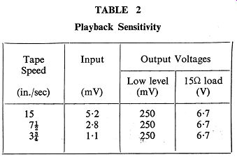
Playback Sensitivity (measured at 5KHz for all tape speeds for 3W audio output or 250mV low-level output)
(a) 15 in./sec: 5.2mV (b) 7 1/2 in./sec: 2.8 mV (c) 3 3/4 in./sec: 1.1 mV
TEST PROCEDURE
The four tests outlined below are intended as simple, yet quite effective, checks for the combined record-playback amplifier.
The values given in the various tables and figures were obtained from the prototype amplifier, using Brenell record-playback and erase heads. The bias current used throughout was 1.0mA at a frequency of 60KHz, and the erase-head voltage was about 25V again at a frequency of 60KHz.
Test I - D.C. Voltages
The d.c. voltages at points in the equipment should be tested with reference to Table 1. The results shown in this table were obtained using an Avometer No. 8.
Test II - Amplifier on Playback
Three pieces of equipment are required for this test: (1) A signal generator covering a frequency range from 20Hz to 20KHz; (2) A valve (tube) voltmeter covering a frequency range from 20Hz to 20KHz; (3) A load resistor of 15-ohm with a 6W rating.
The 15-ohm resistor should be connected to the speaker sockets. The record-playback switch SA should be in the playback position and the tone control RV15 should be set for the flat response.
A signal from the generator, having a frequency of 5KHz, should be applied to the record-playback socket (which normally accommodates the connection plug from the record-playback head). The consequent output signals should be measured on the voltmeter, both at the low-level output socket and across the load resistor.
The input voltage should be adjusted to give an output voltage across the load resistor of 67V for each tape speed, and the input required for this output should be noted. The voltage readings that should be obtained are given in Table 2.
With the switch SB set to 15 inches per second, and with the conditions given in the previous paragraph, the gain control should be varied until the output voltage across the load resistor drops to 50mV. The frequency of the signal should then be reduced to 100Hz and the values of boost given in Table 3 should be observed at the 15? load output. The switch SB should be changed to 7 1/2 and 3 3/4 inches per second, and the boost measurement should again be made.
-------------- Fig 4.
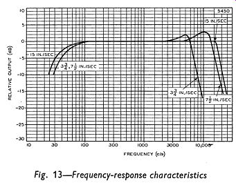
Fig 13
The bass-boost characteristics for the three tape speeds are shown in Fig. 14.
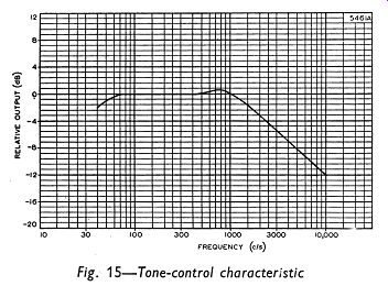
The treble cut introduced by full application of the tone control RV15 should be determined for all tape speeds, and the curve obtained should correspond to that shown in Fig. 15.
Test III - Amplifier on Record
The instruments required for this test are: (1) A signal generator covering a frequency range from 20Hz to 20KHz; (2) A valve (tube) voltmeter* covering a frequency range from 20Hz to 20KHz.
The record-playback and erase heads should be connected to the appropriate sockets in the amplifier, and the equipment should be switched to the recording condition.
For a tape speed of 15 inches per second, a signal at 1KHz should be applied from the generator to the radio input socket. The magnitude of this signal should be such that an output of 30m V is obtained at the low-level output socket.
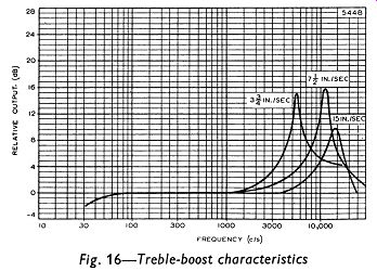
When the signal frequency is switched to 15KHz, the boost indicated in Table 4 should be observed.
For accurate results two separate pieces of p.v.c. covered wire are recommended for the connection to the valve (tube) voltmeter. A coaxial cable may result in considerable errors in the measurements because of the parallel capacitance which is introduced.
With tape speeds of 7 1/2 and 3 3/4 inches per second, the input signal at 1- khz should again be adjusted to give a low-level output of 30m V. The change to input frequencies of 10 and 5KHz should give the treble boost indicated in Table 4.
The treble-boost characteristics for the three tape speeds are shown in Fig. 16. These characteristics will be suitable for many combinations of tape and head, but the peaks may occur at too low a frequency and may indicate too much boost for other combinations. If this is so, modification of the equalization network (that is the components connected to switch SB2) may prove beneficial (see page 89). Any alteration to the treble-boost characteristics will, of course, cause changes in the overall frequency-response characteristics of Fig. 13.
Values for the recording sensitivity for an output voltage measured at the second anode of the ECC83 are given in Table 5. A test of the recording-level indicator should show that the EM81 ‘closes' with approximately 20V at this anode.
An alternative method of checking the recording amplifier is possible. For any of the tape speeds, the voltage developed across a 50 ohm resistor connected in series with the recording head can be observed for the full range of signal frequencies. The response curve so obtained should agree with the appropriate curve for the prototype amplifier, plotted in Fig. 13. For these observations, it will be necessary to disconnect one end of the resistor R34, otherwise only the bias signal will be measured.
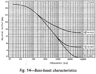
Fig. 14
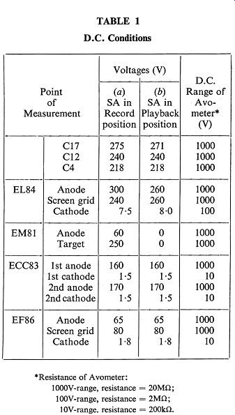
Tbl 2; Tbl 1
------------- Fig. 13, 15, 16
Test IV - Bias Level
For this test, two pieces of equipment are required: (1) A valve (tube) voltmeter which will indicate accurately at frequencies of up to 70KHz; (2) A resistor of 50 ohm.
The resistor should be soldered in series with the earthy end of the record-playback head, and the voltage developed across the resistor, with no input signal, should be measured with the voltmeter.
The voltage developed across the resistor should be 50mV, which corresponds to a bias current of 1.0mA flowing in the 50 ohm-resistor.
-----------
Power-supply Unit
CIRCUIT DESCRIPTION
The circuit diagram for a power supply suitable for use with the 3W tape amplifier and the tape preamplifier described in the following section is given in Fig. 17. The value of R101 will depend on whether the unit is to be used with the amplifier or the preamplifier.
The requirements of the unit are that it should provide (i) a direct voltage of 300V at a current of 50mA for the amplifier and 25mA for the pre-amplifier and (ii) an alternating voltage of 6.3V at a current of 2A.
The choice of rectifier will depend on the tape deck used. Normally, the Mullard full-wave rectifier, type EZ80, will be suitable. However, with tape decks that use electrical braking for the tape transport system, it is essential that the Mullard type EZ81 be used, so that the current which is required for the short braking periods can be supplied.
If the EZ80 is used, the series resistance in each anode circuit of the rectifier must be at least 21552; if the EZ81 is used, the minimum series resistance is 200-ohm for each anode. Very few transformers meeting the specification given below will have a total winding resistance less than these minimum requirements, but should it be lower, a series resistance large enough to make up the minimum should be added to each anode circuit. The required value of this series resistance is derived in the way shown on page 28.
The values of the dropper resistors R100 and R101 shown in Fig. 17 should be chosen to give respectively a potential of less than 350V across the reservoir capacitor C100 and a potential of 300V across C101. It may be found that R100 is not needed.
CONSTRUCTIONAL DETAILS
-----------
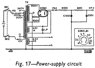
Fig. 17.
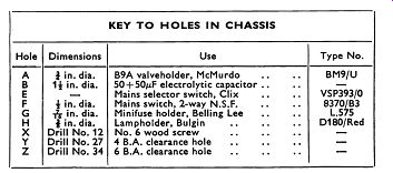
The chassis consists of one piece of 16 s.w.g. aluminum sheet, 8 3/4 in. long, and 7 in. wide. It should be marked as shown in the chassis drawing of Fig. 18 and the holes should be cut as indicated. Mounting holes for the mains switch, the fused voltage-selector and the pilot lamp are shown in the figure, but if it is so desired, these components may be mounted elsewhere when, of course, there will be no need to cut the particular holes in this chassis.
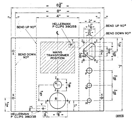
The chassis drawing shown in Fig. 18 is for a mains transformer of the inverted-mounting type. If a different type is used, it will be necessary to drill grommet holes to enable the leads to be taken through the chassis.
The assembly of the power unit should be accomplished quite easily by referring to the layout diagram of Fig. 19. This figure again caters for a transformer of the inverted-mounting type.
---------
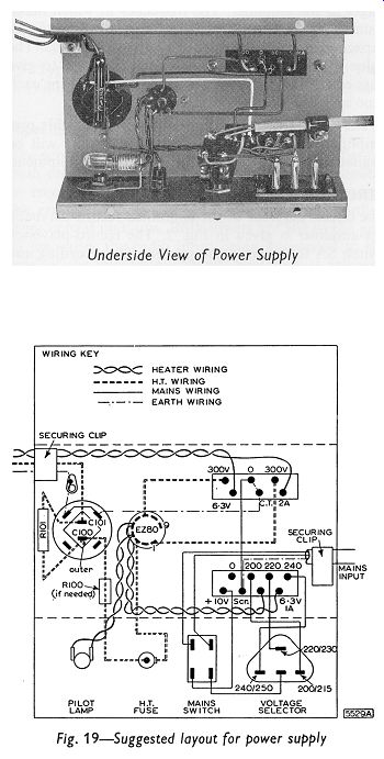
Fig. 19
To avoid unnecessary expense. input and output plugs have not been used: securing clips suffice to anchor the mains and h.t. leads. The pilot lamp is also an optional component.
It is very important when wiring the electrolytic capacitor to ensure that the correct section is used as the reservoir capacitor C100. The section which is identified as the ‘outer', or else marked with a red spot, should be used for this component.
========