| Home | Audio mag. | Stereo Review mag. | High Fidelity mag. | AE/AA mag. |
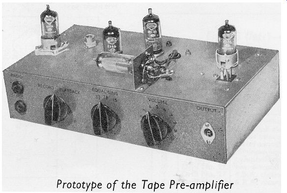
The tape-recording pre-amplifier described in this section is intended to be used in conjunction with a high-quality pre-amplifier and power amplifier. The unit combines the function of both recording and playback amplification, although, for the playback operation, it acts only as an equalizing stage, giving sufficient output voltage to drive the high-quality amplifying system.
The general principle of the design has been to preserve simplicity as far as is compatible with high-quality performance. The distortion introduced in the recording channel has been reduced to such an extent that it is probable that the quality of performance will be limited only by the magnetic tape itself, provided, of course, that the tape deck used is of satisfactory performance. The level of total harmonic distortion in the recording process should not be greater than 0.5 % with a recording current of 150µA through the head.
Equalization to correct for head and tape characteristics is provided for each of the tape speeds: 3 3 /4, 7 1 /2, and 15 inches per second. The high-frequency equalization is applied during the recording process and the low-frequency correction during playback.
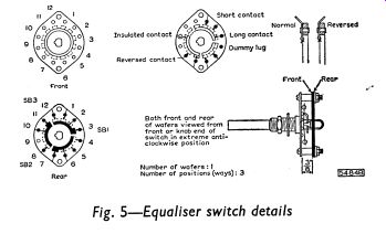
Treble equalization is achieved by using a wound Ferroxcube pot-core inductor, Mullard type WF816, in a resonant circuit between the first and second stages of the amplifier. The frequency at which maximum treble boost occurs is determined by the tuning capacitance which is adjusted by the switch SB3. The value of resistance in the feedback network to give bass equalization during playback is selected for each tape speed by the switch SB1.
There is no provision for tone control in this preamplifier. It is anticipated that such control will be available with the associated amplifying equipment.
CIRCUIT DESCRIPTION
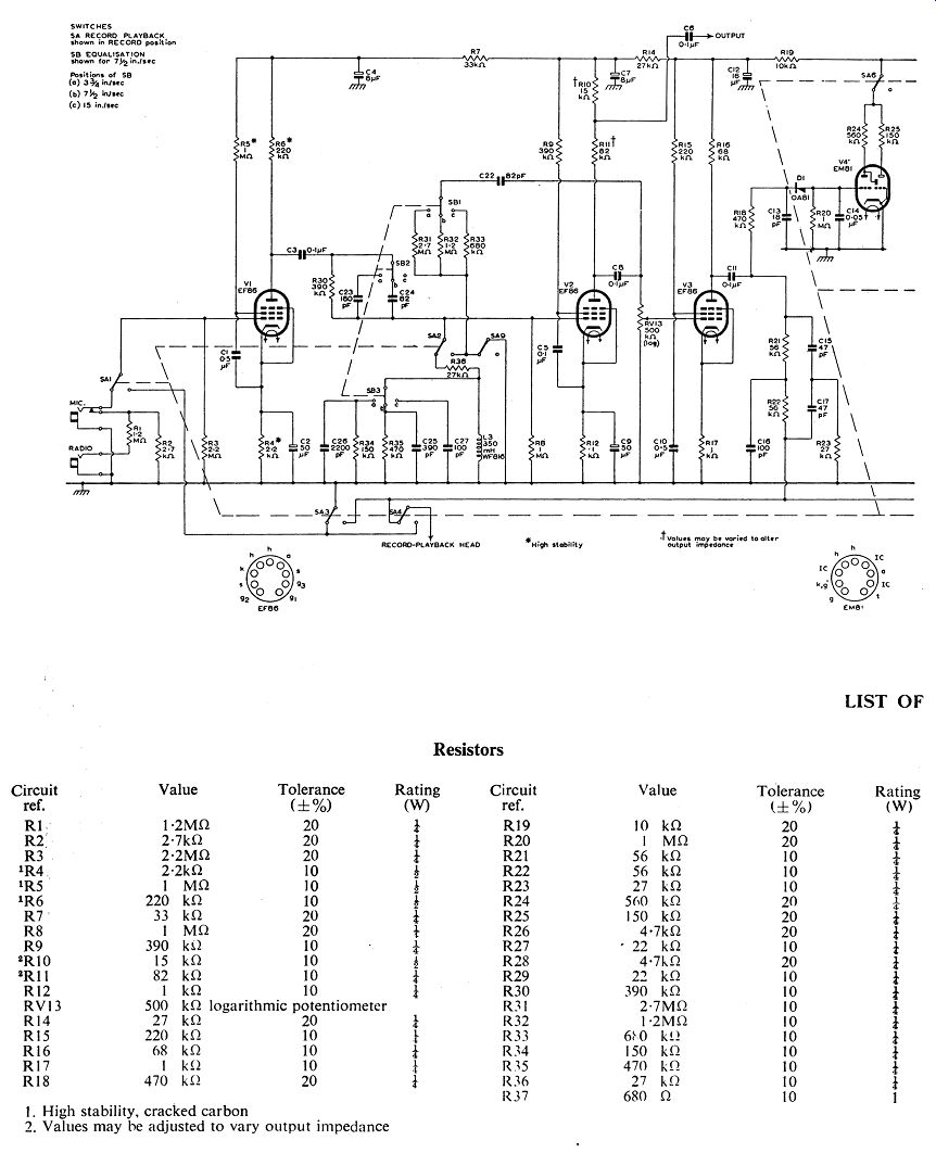
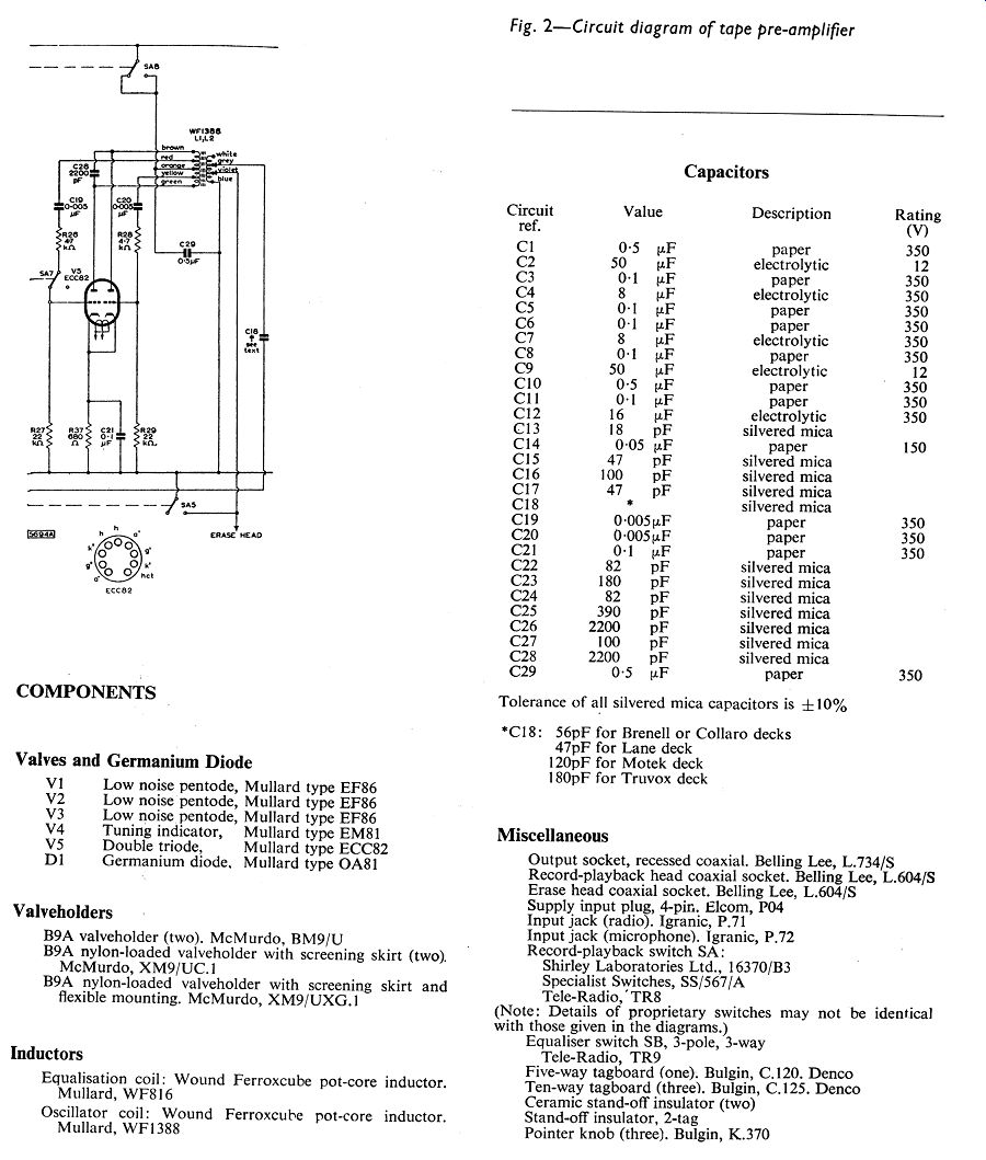
The circuit diagram of the combined record-playback pre-amplifier is given in Fig. 2. The record-playback switch SA is shown in the position for recording and the equalizer switch SB is set for equalization at a tape speed of 7 1/2 inches per second. The playback output is taken from the anode of the second EF86, and the remaining stages are used only for the recording operation.
Controls
Two switch banks are used in the pre-amplifier. Switch SA provides the change from the recording to the playback process, and switch SB provides the equalization appropriate to one of the tape speeds: 3 3 /4, 7 1 /2, and 15 inches per second.
The gain control RV13 is the only other control in the pre-amplifier.
Valve (tube) Complement
The complete pre-amplifier uses five Mullard valve (tube) s and one Mullard germanium diode. These are:
(a) Type EF86, low-noise pentode, used in the input stage.
(b) Type EF86, used in the second stage.
(c) Type EF86, used in the output stage for recording.
(d) Type ECC82, double triode, used as a push-pull oscillator for the bias and erase signals.
(e) Type EM 81, tuning indicator, used in the recording-level stage.
(f) Type OA 81, germanium diode, used as the indicator-circuit rectifier.
Input Stage
The pentode, type EF86, acts as a voltage amplifier for both recording and playback processes. It is possible to record from either microphone or radio sources, the radio input also being convenient for recording from crystal pick-ups. Both inputs are fed to the grid of the valve (tube) , the radio input being attenuated to the level of the microphone input. Switching is achieved by inserting the jacks, so that only one input may be used at a time.
Equalizer Stage
As was stated above, no tone control is incorporated in this stage. The output is taken during playback from across part (R10) of the anode load of the second EF86. The output supplied is 250mV at a source impedance of 15 k-o. A rearrangement of the anode load resistance (that is, R10 and R11) can be made, if required, to give an output of, for instance, IV at a source impedance of 60 k-o.
The output of the second stage of the amplifier is fed during the recording process from the anode of the EF86 by way of the gain control RV13 to the grid of the following EF86.
A resonant circuit containing a wound Ferroxcube pot-core inductor L3 (Type WF816) is used to provide treble equalization. The value of tuning capacitance in the resonant circuit is selected by the switch SB3 to give the maximum treble boost at frequencies appropriate to the tape speed used. The extent of treble boost is controlled by the resistor R30 and the damping resistors R34 and R35 connected in parallel with the capacitors C26 and C25. The steep rise in boost which occurs below the resonant frequency is modified by damping the inductance, and by partially shunting the resistor R30 at the appropriate frequency.
The treble boost obtained will be correct for many combinations of tape and head, but it may be too great for others. If this is so, the damping on L3 should be increased by connecting a resistor in parallel with C27 and reducing the values of R34 and R35. The optimum values should be determined by listening tests.
The values of the resistors R31, R32 and R33 arranged on switch SB1 have been chosen to give appropriate feedback for bass equalization during playback. To avoid capacitive coupling, this section of the equalizer switch is arranged on the front of the switch wafer.
Recording Output Stage
The third stage of the unit, operative only during the recording process, uses another EF86, the grid of which is fed from the volume control RV13. The stage is designed to give low harmonic distortion at peak levels of recording current, and the distortion should not exceed 0.5 % for a recording current of 150µA.
The recording current is fed to the recording head by way of a parallel-T network, which acts primarily as a bias-voltage rejector circuit. The series resistance of the network is needed in this stage to ensure a constant drive to the head, and its inclusion is also desirable to preserve a satisfactory a.c./d.c. load ratio for the EF86 of the third stage.
H.F. Oscillator Stage
The halves of the double triode are arranged as a push-pull oscillator.
The stage is designed so that the ECC82 draws approximately the same h.t. current during playback, when it is inoperative, as it does under its oscillatory conditions during recording. In this way, the total current drain for either the recording or the playback process does not alter greatly, and the design of the power supply is consequently simplified.
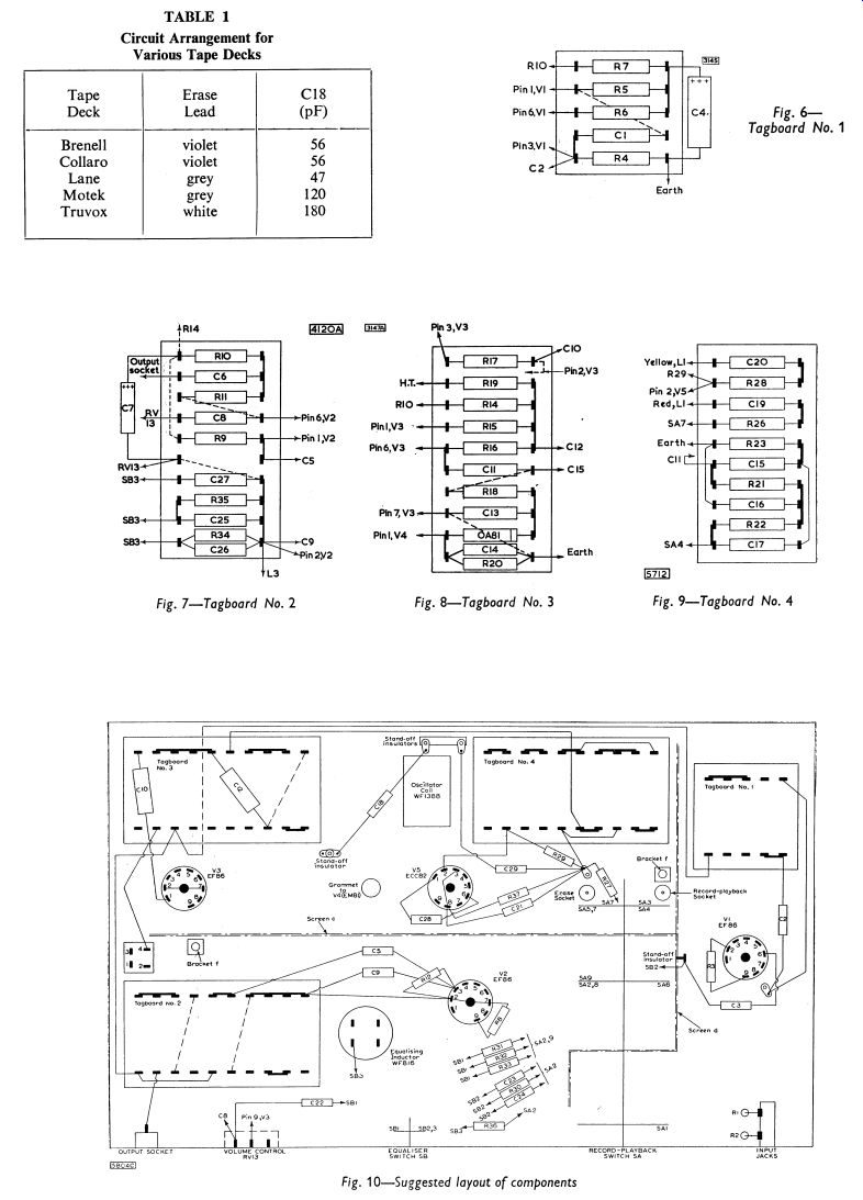
The oscillator coil consists of a wound Ferroxcube pot-core, type WF1388, in which the secondary windings are tapped so that the coil can be used with most of the commercially available tape decks. The value of the coupling capacitor C18 will vary with the type of record-playback head used, and a list of appropriate values is given in Table 1.
---Fig. 1
Power Supply
The unit described in Section 11 is suitable for use with the pre-amplifier circuit. The heater-current requirements of the two tape circuits are similar; allowance for the difference in h.t. currents is made by a suitable choice of value for R101.
CONSTRUCTION AND ASSEMBLY
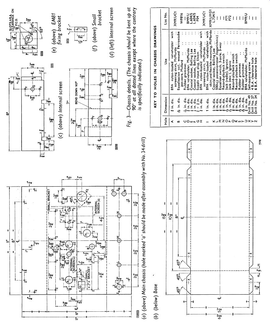
The chassis for the tape pre-amplifier is made up of seven separate pieces of 16 s.w.g. aluminum sheet. The dimensions (in inches) of these are:
(a) Main chassis 11 x 11 (b) Base 15 3 /4 x 6 5 /8 (c) Internal screen 8 x 2 3 /8 (d) Internal screen 7 x 23 /8 (e) EM81 mounting bracket 13 /4 x 13 /4 (f) Small bracket (two) 1 1 /4 x 1 /2
Each piece should be marked as shown in the chassis drawings of Fig. 3, and the holes should be cut as indicated. It is important that, when bending the sheet, the scribed lines should be exactly along the angles. This ensures that the pieces will fit together properly when assembled.
--------------
------------
-----
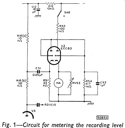
Recording Level Indicator
The tuning indicator, type EM81, used in this stage is fed from the anode of the recording stage. The large series resistance R18 is used to minimize the loading of the recording stage. If a meter indication of the recording level is required, the circuit given in Fig. 1 can be used in place of the EM81. This alternative arrangement is similar to that suggested on page 92 for the 3W tape amplifier.
Details of the record-playback switch SA are given in Fig. 4. Before assembling this switch around the screens, it will probably be found convenient to fix the following components to the chassis:
(1) The erase and record-playback coaxial sockets which have to be fitted to the chassis beneath wafer 3 of the switch.
(2) All the valve (tube) holders. Only the three EF86 valve (tube) s should be skirted, and the holders for these valve (tube) s should be nylon-loaded. The holder for the input valve (tube) V1 (EF86) should be of an anti-microphonic type - that is, having a flexible mounting.
(3) The two small brackets (f) which should be bolted to the internal screens (c) and (d) as shown in the layout diagram in Fig. 10.
The construction is best continued after the above components have been fitted by assembling wafers 1 and 2 around the internal screens.
The wafers should be arranged so that positions 6 and 7 are nearest the chassis and the face of each wafer described as ‘rear' in the switch diagram (Fig. 4) is farthest from the switch plate. The internal screen (c) should be added to the assembly, both screens should be bolted together, and wafer 3 should be fitted in position, again with its ‘rear' face farthest from the switch plate. The general arrangement of the switch wafers and internal screens is shown in Fig. 10. The use of a shake-proof washer is recommended between the switch plate and the front panel when the switch and screens are fitted to the main chassis.
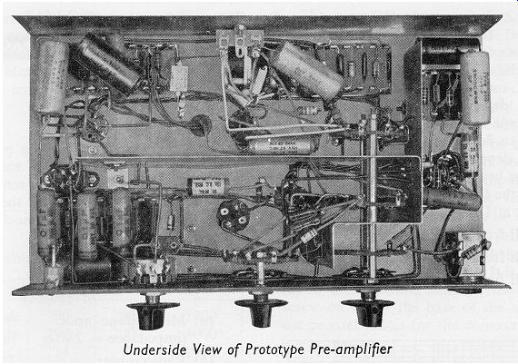
The arrangement of the smaller components on tagboards is shown in Figs. 6 to 9, and a suitable layout of these boards and the other components in the chassis is shown in Fig. 10. In fitting the EM81 mounting bracket, the valve (tube) holder should be fastened to the bracket so that the solder tags are on the same side as the flange on the bracket. The gap between pins 1 and 9 on the holder should face the flange to ensure that the tuning eye of the EM81 faces forward. The indicator should appear in the center of the front panel of the equipment, and the bracket should be bolted to the chassis in the correct position for this to be so. The valve (tube) holder can be fixed in the main chassis, as described in Section 11, if it is required to mount the EM81 at the end of extension leads. An extra hole with a diameter of 1 in. will have to be drilled for the valve (tube) holder, in place of the grommet hole C shown in Fig. 3(a).
Identification of the coil winding suitable for the erase heads of various decks can be made by referring to Table 1. The appropriate value of C18 is also given in this table. The bias capacitor is connected to the grey lead from the secondary winding for all the makes of deck indicated. The connections in the diagram for the primary winding of the coil and for the blue (earth) lead from the secondary winding are also the same for the decks listed.

------Fig. 4
------- Fig. 5
--------- Figs and Tables
-----------
-------- Fig. 11
PERFORMANCE Frequency Response
The overall response of the recorder depends on the type of head used, the magnitude of the bias current, and, to some extent, on the tape employed. The low-frequency response depends on the amplifier used rather than on the type of head, and in this design, it will not be more than 3dB down at 50Hz. The high-frequency response depends on the tape speed and the gap width of the head. With heads having a gap width of 0.0005in., the following performance figures (relative to the level at 1- khz) can be obtained:
15 in./sec: ±3dB from 35Hz to 17KHz 71 /2 in./sec: ±3dB from 50Hz to 13KHz 33 /4 in./sec: ±3dB from 50Hz to 6KHz
Flexibility has been achieved in the treble-boost circuits of the pre-amplifier. Consequently good control of the complete response of the pre-amplifier is possible; and equalization to reasonably high frequencies is practicable. However, the degrees of control and equalization depend on the individual adjustments of component values to suit the head and tape being used. The component values given in this section apply only to the pre-amplifier when it is used with Scotch recording tape and a Collaro tape deck.
Ferroxcube pot-core inductors are adequately screened to prevent excessive hum or stray bias being picked up, and they do not appear to cause more circuit-ringing than RC networks which produce the same treble boost.
The playback characteristic of the pre-amplifier conforms to the C.C.I.R. specification, thus permitting excellent reproduction of pre-recorded tapes.
The recording characteristic is arranged to give a flat frequency response in conjunction with this playback characteristic. Additional head losses occurring during playback will normally be capable of correction by the tone controls in the associated amplifying systems.
Sensitivity
The sensitivity of the recording process is measured with the control RV13 set for maximum gain. This does not apply to the playback sensitivity because the gain control is not operative at the point from which the output is taken for the associated equipment.
Recording Sensitivity
(measured at 1- khz, with recording-head audio current of 150µA) (a) Microphone input: 0.5mV for peak (impedance = 2M-o) recording level (b)Radio input: 250mV for peak (impedance = 1.2M-o) recording level
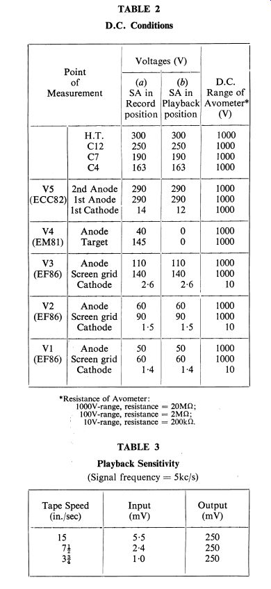
Playback Sensitivity
(measured at 5KHz for each tape speed for output of 250mV) (a) 15 in./sec: 5.5mV (b) 7 1 /2 in./sec: 2.4mV (c) 3 3 /4 in./sec: 1.0mV
TEST PROCEDURE
The four tests outlined below are intended as simple, yet quite effective, checks for the pre-amplifier.
The values given in the various tables and figures were obtained from the prototype pre-amplifier, using Collaro record-playback and erase heads. The bias current used throughout was 1.0mA at a frequency of 60KHz, and the erase-head voltage was about 25V, again at a frequency of 60KHz.
Test I - D.C. Voltages
The d.c. voltages at points in the equipment should be tested with reference to Table 2. The results shown in this table were obtained using an Avometer No. 8.
Test II - Amplifier on Playback
Two pieces of equipment are required for this test:
(1) A signal generator covering a frequency range from 200/s to 20KHz; (2) A valve (tube) voltmeter covering a frequency range from 200/s to 20KHz.
The record-playback switch SA should be in the playback position. A signal from the generator, having a frequency of 5KHz, should be applied to the record-playback socket (which normally accommodates the connecting plug from the record-playback head). The consequent output signal should be. measured on the voltmeter at the output socket.
The input voltage should be adjusted to give an output voltage at the output socket of 250mV for each tape speed, and the input required for this output should be noted. The voltage readings that should be obtained are given in Table 3.
----------
------- Tables
For operation at such high sensitivities, great care should be taken to ensure that the signal measured is, not composed mostly of hum. It is advisable, therefore (a) to use screening cans on the three EF86, (b) to screw on firmly the base of the amplifier, and (c) to use coaxial cables for the connections to the measuring equipment.
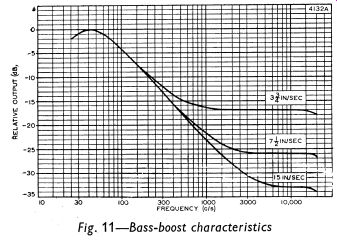
The input voltage at 5KHz should be varied until the output voltage drops to 50mV. The frequency of the signal should then be reduced to 40Hz and the values of boost listed in Table 4 should be observed at the output socket.
The bass-boost characteristics for the three tape speeds are shown in Fig. 11.
Test III - Amplifier on Record
The instruments required for this test are:
(1) A signal generator covering a frequency range from 20Hz to 20KHz; (2) A valve (tube) voltmeter 1 covering a frequency range from 20Hz to 20KHz.
The record-playback and erase heads should be connected to the appropriate sockets in the preamplifier, and the equipment should be switched to the recording condition.
A signal at 1- khz should be applied from the generator to the radio input socket. The magnitude of this signal should be such that an output of 15m V is obtained at the output socket.
The boost indicated in Table 5 should be obtained at the appropriate tape speed when the signal frequency is altered to the value shown in the table.
The treble-boost characteristics for the three tape speeds are shown in Fig. 12. These characteristics will be suitable for many combinations of tape and head, but the peaks may occur at too low a frequency and may indicate too much boost for other combinations. If this is so, modification of the equalization network (that is the component connected to switch SB3) may prove beneficial. Any alteration to the treble-boost characteristics will, of course, cause changes in the overall frequency-response characteristics of the pre-amp.
'For accurate results, two separate pieces of p.v.c. covered wire are recommended for the connections to the valve (tube) voltmeter. A coaxial cable may result in considerable errors in the measurements because of the parallel capacitance which is introduced.
Values for the recording sensitivity for an output voltage measured at the anode of V3 (EF86) are given in Table 6. A test of the recording-level indicator should show that the EM81 ‘closes' for each tape speed with approximately 15V at the anode of the recording-output valve (tube) .
An alternative method of checking the recording amplifier is possible: for each tape speed, the voltage developed across a 50 ohm resistor connected in series with the recording head can be observed for the full range of signal frequencies. The response figures so obtained should agree with the values obtained with the prototype pre-amplifier and listed . For these observations, it will be necessary to disconnect one end of the resistor R26, otherwise only the bias signal will be measured.
Test IV - Bias Level
For this test, two pieces of equipment are required:
(1) A valve (tube) voltmeter which will indicate accurately at frequencies of up to 70KHz; (2) A resistor of 50 ohm .
The resistor should be soldered in series with the earthy end of the record-playback head, and the voltage developed across the resistor, with no input signal, should be measured with the voltmeter.
The voltage developed across the resistor should be 50mV, which corresponds to a bias current of 1.0mA flowing in the 50 ohmresistor.
========