The Hartley oscillator shown in the accompanying diagrams ranks high in popularity when radio-frequency oscillator circuits are mentioned. Recall that the function of any oscillator circuit is to generate an alternating current at the desired frequency.
This circuit will be explained by assuming the desired frequency to be within the broadcast band-for example, 1,000 kilocycles (1,000,000 cycles) per second. Figs. 1 through 4 show the operation of the Hartley oscillator during each quarter-cycle. The necessary circuit components are as follows:
C1-Radio-frequency tank capacitor.
L1-Radio-frequency tank inductor (also acts as an auto transformer).
C2-Grid-coupling capacitor.
R1-Grid-leak biasing resistor.
V1-Oscillator tube.
M1-Power supply.
Here are the currents at work in this circuit, and the colors they are shown in:
1. Oscillating tank current (blue)
2. Plate current (solid red)
3. Grid-leak biasing current (solid green)
4. Grid-driving current ( dotted green)
5. Feedback current ( dotted red).
Feedback occurs in the Hartley oscillator as current is drawn to the cathode through the tapped portion of coil L1. As more and more tube current (shown in solid red) flows, autotransformer action occurs between the tapped portion of L1 and the whole coil, causing another component of current to flow down-ward through the coil. This is the feedback current, shown by the dotted red lines.
How the voltage polarities and current movements in the tuned tank are correlated with those in the cathode circuit of the tube, so that the feedback will have the appropriate phase to support the oscillation, will be discussed later. First, let us look at the individual currents in detail.
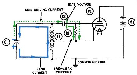
Fig. 1. Operation
of the Hartley oscillator-first quarter-cycle.
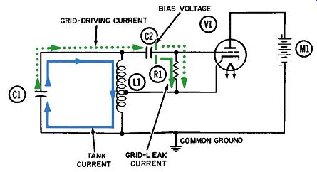
Fig. 2. Operation of the Hartley
oscillator-second quarter-cycle.
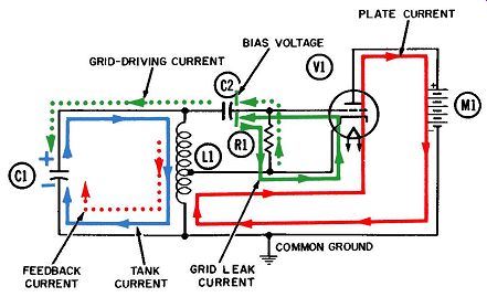
Fig. 3. Operation of the Hartley oscillator-third
quarter-cycle.
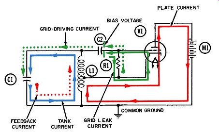
Fig. 4. Operation of the Hartley oscillator-fourth quarter-cycle.
OSCILLATING TANK CURRENT
Twice each cycle, the oscillating current (shown in blue) moves from plate to plate of tank capacitor C1, via coil L1. The values chosen from C1 and L1 are such that these two components will be resonant at the desired frequency--1,000,000 cycles per second in our example. These values can be deter mined from the standard formula for finding the resonant frequency: f= 1/2 pi LC
Fig. 1 shows the first quarter-cycle, during which the current flows from the lower plate of capacitor C1 to the bottom of coil L1 and through it, onto the upper plate of C1. The surplus of electrons makes the upper plate of C1 more negative than the lower one, as indicated by the blue minus sign.
This charging of the upper plate of tank capacitor C1 also de livers electrons to the left plate of coupling capacitor C2, which becomes charged to the same negative voltage. The number of electrons flowing onto the left plate of coupling capacitor C2 is accompanied by an equal number flowing away from the opposite plate. The resulting current, shown in dotted green, develops the grid-driving voltage across resistor R1.
The circuit diagram for the first quarter-cycle (Fig. 1) shows conditions as the grid-driving voltage becomes more and more negative. Electrons are flowing downward through R1, so we know it is more negative at the top, since electrons always flow from a more negative to a less negative area.
The second diagram (Fig. 2) denotes the second quarter cycle, when the tank current has reversed its direction. There is no electron flow in the tank at the start, but once the flow starts, it builds up rapidly and reaches maximum at the end of the quarter cycle. The electrons formerly concentrated on the upper plate of tank capacitor C1 and the left plate of coupling capacitor C2 are distributed equally between both plates of C1 the moment the quarter-cycle ends. Now the tank voltage (measured at the top of the tank) is zero.
The waveform diagrams in Fig. 5 show this relationship.
In interpreting sine-wave diagrams of current and voltage, it would be wise to clarify some basic assumptions. In the wave form representing tank current, the half-cycles above the reference line are arbitrarily chosen to represent electron current flowing from the upper plate of tank capacitor C1 to the lower plate ( through tank coil L1, of course) . The half-cycles below the reference line represent electron current flowing in the opposite direction, or upward through L1.
Whenever the sine waves cross the reference line, current is flowing in neither direction (meaning there is zero current). At this time the current is changing direction. As an example, at the end of the first quarter-cycle, electrons have been flowing upward and charging the upper plate of C1 with a negative voltage. During the second quarter-cycle, this current reverses and begins flowing downward.
By the end of the second quarter-cycle, the current is flowing downward through L1 at the maximum rate, and the negative voltage on the upper plate of C1 has discharged to zero. During the third quarter-cycle (Figs. 3 and 5), this downward electron flow continues, building up a peak negative voltage on the lower plate, and a peak positive voltage on the upper plate, of capacitor C1.
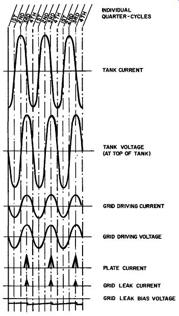
Fig. 5. Hartley-oscillator waveforms. At the start of the fourth quarter-cycle,
the electron current in the tank again reverses direction, as shown in Figs.
4 and 5, and begins flowing upward through coil L1. This action begins
discharging the negative voltage on the lower plate of C1.
So, at the end of the fourth quarter-cycle, the voltage on both capacitor plates is again equalized and the voltage at the top of the tank is zero.
During the entire first two quarter-cycles, no current can flow through the tube itself because of the combination of permanent negative bias and instantaneous grid-driving voltages. The origin of the negative bias voltage becomes apparent when we study the action during the third quarter-cycle, depicted in Figs. 3 and 5. The tank current has now completed its journey through the inductor to the lower plate of the tank capacitor, charging the plate negatively and at the same time leaving a deficiency of electrons on the upper plate (which we know to be a positive voltage) . Electrons are also being drawn away from the left plate of coupling capacitor C2 and, in turn, away from the grid area of the tube and upward through grid resistor R1. (This electron flow is shown in dotted green to differentiate it from the grid leak current shown in solid green.) An instantaneous positive voltage is created at the grid and momentarily exceeds the permanent negative bias voltage. The result is that current is per mitted to flow from cathode to plate at the end of the third quarter-cycle.
The plate current (shown in solid red) flows during the latter part of the third and first part of the fourth quarter-cycles, as shown in Fig. 5. This current will flow whenever the grid voltage is less negative than the cutoff voltage of the tube.
Grid-leak current (in solid green) flows for an even shorter time. This occurs at the end of the third and the start of the fourth quarter-cycles, when the instantaneous grid voltage is positive enough that the grid wires will attract and capture the negative electrons.
It is during the third quarter-cycle that the control-grid voltage is raised above the cutoff value and tube current flows. For the remainder of the cycle, the control-grid voltage becomes less and less negative as the tank current completes its journey through the tank inductor to the lower plate of the tank capacitor. As the grid voltage becomes less negative, the current through the tube continues to increase. The complete path for this tube current (shown in solid red) includes the lower portion of tank inductor L1.
When tapped in this fashion, an inductor is called an auto transformer. The action of an autotransformer is identical to that of a conventional transformer, where the windings are separated. The tube current shown in solid red can be considered the primary current in this transformer action, and the current it sets up in the tank circuit (shown in dotted red) is the secondary current. The latter is appropriately labeled the feedback current, since it transfers energy from the output (plate circuit) to the input (grid circuit). Feedback in an oscillator circuit hinges on two essentials: One is a means for transferring energy from output to input.
The other is that this energy must be in the proper phase to reinforce the oscillation in the grid tank circuit. The following discussion will show how the second essential is achieved.
The tube current in the cathode circuit flows in one direction only-from the common ground to the cathode, through the tube to the plate, then through the power supply and back to ground. However, transformer action will occur just as readily whenever a direct current increases or decreases as it will for outright reversals in the direction of current flow.
In Fig. 5 we see that plate current begins to flow during the third quarter-cycle, and that it builds up to maximum at the end of this quarter-cycle. Since all inductors act to oppose any change in current, this build-up will cause another current to flow in the opposite direction and buck the tube current as it passes through the lower portion of coil L1. This bucking current is called the counter emf (also, the back emf or back voltage) of the inductor and is shown in dotted red in Fig. 3.
As the third quarter-cycle comes to a close, this counter-, or secondary, current (shown in dotted red) also stops flowing in the tank circuit. During its brief life it has been flowing in the same direction as the tank current, thereby being at least partially in phase with the tank current and thus reinforcing it.
The fact that such reinforcement has occurred can also be deduced from the following observation: At the end of the third quarter-cycle, both currents have independently delivered electrons to the lower plate of the tank capacitor and increased its negative voltage.
This secondary current both starts and stops during the latter part of the third quarter-cycle. Therefore, as depicted in Fig. 6 by the distorted sine wave representing feedback current, an entire half-cycle has occurred in less time than a quarter-cycle of tank current.
At the beginning of the fourth quarter-cycle, the tank current begins to flow upward through tank inductor L1, tending to neutralize the positive voltage on the upper plate of C1. An examination of the sine-wave relationships for this circuit (Fig. 5) will reveal that the tank voltage, plus the resultant grid driving current and its attendant voltage developed across resistor R1, are all essentially in phase. Consequently, during the fourth quarter-cycle the positive tank-voltage decreases to zero and the positive grid voltage also disappears.
A reduced grid voltage in turn lowers the plate current flowing through the tube and, of course, through the lower portion of the inductor. This decrease in what we earlier identified as "primary" current results in transformer action between the whole winding and its lower portion. As before, the transformer action will oppose any change in current, so a secondary current starts flowing upward through the winding in a steadily increasing amount to compensate for the corresponding drop in the primary current.
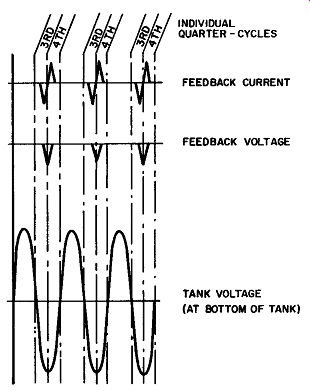
Fig. 6. Feedback-current and
-voltage wave forms in the Hartley oscillator.
The plate current is cut off midway in the fourth quarter cycle, and this secondary current also quickly drops to zero. During its brief span the secondary current flowed in the same direction as the tank current and the two can be considered roughly in phase. Again, the" secondary current thus reinforces the oscillation in the tank. Fig. 6 shows that the feedback current will again go through half a cycle in less time than the tank current and voltage require for a quarter-cycle. It is also fairly obvious that the whole cycle of feedback current is a very distorted sine wave. Although not shown on its sine wave, the tank voltage (and current) will in turn be distorted, resulting in higher positive than negative peaks. An even more important phenomenon resulting from this and most other feedback is a shift in the tank frequency. In a Hartley oscillator, this shift is toward the lower end of the spectrum; therefore the circuit oscillates at a some what lower frequency than that computed using the standard frequency formula.
The feedback current drives additional electrons to the lower plate of tank capacitor C1. As a result, a negative pip (pulse) of voltage occurs at the end of each third quarter-cycle, as shown in Fig. 6. This extra component is then added to the tank voltage.
Fig. 5 shows the changes in voltage, measured at the top of the tank, during each quarter-cycle.
For the sake of convenience, this sine wave has been inverted in Fig. 6 to show the tank voltage at the bottom of the tank. As you can see, the feedback-voltage pips are now in phase with the tank voltage and will reinforce it each cycle.