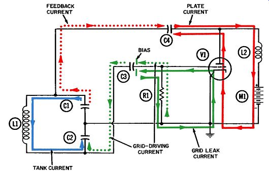
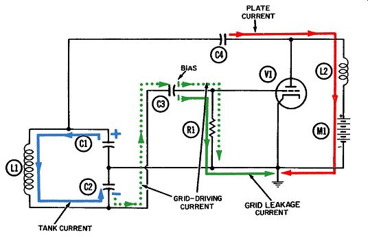
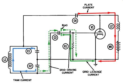
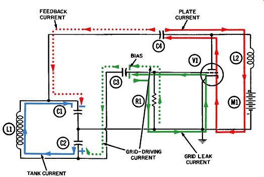
The Colpitts oscillator is another widely used circuit whose function is to generate a continuous alternating current at a fixed radio frequency. The Colpitts oscillator is usually operated under Class-C conditions, which means plate current flows during less than half of each cycle. Figs 1 through 4, depicting successive quarter-cycles, serve to explain how this circuit operates. The essential circuit components and their functional titles are as follows:
L1-Radio-frequency tank inductor.
C1 and C2--Radio-frequency tank capacitors.
C3-Grid coupling capacitor.
R1-Grid-leak biasing resistor.
V1-Oscillator tube.
C4-Feedback and blocking capacitor.
L2-Radio-frequency choke.
Each of the currents at work in the circuit is shown in a separate color for easier identification and analysis. The currents and their corresponding colors are:
1. Radio-frequency tank current (solid blue).
2. Unidirectional plate current (solid red).
3. Grid-leak biasing current (solid green).
4. Grid-driving current (dotted green).
5. Feedback current ( dotted red) .
Fig. 5 shows representative waveforms of the currents and voltages in this circuit. Two complete cycles are included, with dividing lines between each quarter-cycle so that momentary points on the waveforms can be related to their respective current directions and voltage polarities.
As in the Hartley oscillator, the feedback impulse is applied at the end of the tank opposite the grid connection. When the top of the tank is negative, the bottom is positive, and vice versa.
Figs. 1 and 2 show the tank current flowing in a direction which delivers electrons to the lower plate of tank capacitor C2.
At the end of the first quarter-cycle there is no voltage on the plates of C1 and C2, although maximum tank current is flowing between them. Proper interpretation of the tank-current sine wave of Fig. 5 tells us that peak amplitude is also the moment of maximum current. This particular sine wave has been drawn so that any displacement above the reference line means electrons are flowing downward through the tank coil, or away from the upper plate of C1, resulting in a positive voltage at this point.
By the same token, any displacement of the sine wave below the reference line means just the opposite--electrons are flowing upward through the tank coil, toward the upper plate of C1, resulting in a negative voltage there. The tank voltage waveform of Fig. 5 is the waveform appearing at this point.
At the end of the second quarter-cycle, the tank current has stopped flowing; this is also the moment the current sine wave crosses the reference line. Electrons have been delivered to the lower plate of C2, giving it maximum negative voltage. Likewise, the upper plate of C1 has an equivalent deficiency of electrons, or a peak positive voltage. These two voltage peaks are indicated in Fig. 2 by appropriate minus and plus signs on C2 and C1 respectively.
The grid-driving currents, shown in dotted green in Figs. 1 through 4, are driven by the oscillating voltage in the tank circuit and constitute the main load on it. The grid driving cur rent is external from the tank current/voltage combination and, as such, is in phase with the voltage at the bottom of the tank.
The voltage which this current develops across grid resistor R1 will be in phase with the driving current at all times (because current and voltage in a resistive path are always in phase with each other). Consequently, the grid-driving voltage will be in phase with the tank voltage when measured at C2, and exactly out of phase with the tank voltage when measured at the top of the tank, as portrayed in Fig. 5.
The directions indicated in Figs. 1 through 4 for the grid driving current are the result of electron concentration (negative voltage) or deficiency (positive voltage) on the lower plate of tank capacitor C2. For instance, during the second and third quarter-cycles, there is always some negative voltage on C2, so the grid-driving current is repelled from it. But during the first and fourth quarter-cycles, the positive voltage on C2 draws the grid-driving current toward this point.
As explained previously, current does not actually flow through grid coupling capacitor C3--the electrons flowing onto one side of the capacitor drive an equal number off the other side. Conversely, whenever electrons are drawn off one plate of a capacitor, an equal number will be attracted to the other plate.
The grid-driving current will develop a positive-going voltage across resistor R1 during the fourth quarter-cycle. Midway through this quarter-cycle, the positive voltage cancels out the more permanent negative voltage resulting from grid-leak biasing action. The grid voltage is now less negative than the cutoff voltage, and plate current will start to flow through the tube.
(The cutoff voltage is a negative value below which tube current cannot flow, and above which it can.) Plate current begins to flow during the fourth quarter-cycle, as indicated in Fig. 5, and steadily increases until the grid voltage reaches zero just before the fourth quarter-cycle ends.
The conventional path for unidirectional plate currents is through the tube from cathode to plate; then through any load, where the essential work of the circuit is done; and finally, through the power supply to a common ground which provides the necessary return to the cathode. This plate circuit is no exception, as you will note by the solid red path in Fig. 4. The load is made up of feedback capacitor C4 and radio-frequency choke L2. It is necessary that the plate current flow onto the right plate of C4, and the radio-frequency choke is placed in the circuit to make sure it does.
A radio-frequency choke, as its name implies, will stifle the passage of radio-frequency currents. A choke is nothing more than an inductor, and the universal property of any inductor is that it will oppose any change in current. The amount of opposition depends on the inductance and on the frequency of the cur rent trying to flow, as related by the mathematical formula for inductive reactance:
Xr, = 2 pi fL.
While the plate current is increasing, it is unable to enter the choke, even though the normal path is through the choke to the power supply. Momentarily succumbing to this opposition, the plate current is diverted down the only other path available to it and heads for the right plate of feedback capacitor C4. This influx of electrons onto one plate of C4 drives an equal number away from the other plate and toward the tank circuit.

Fig. 1. Operation of the Colpitts oscillator-first quarter-cycle.

Fig. 2. Operation of the Colpitts oscillator-second quarter-cycle.

Fig. 3.
Operation of the Colpitts oscillator-third quarter-cycle.

Fig. 4. Operation
of the Colpitts oscillator-fourth quarter-cycle. This is the way a feedback
pulse is delivered from the output to the input circuit. The feedback current,
shown in dotted red, should arrive in phase with the tank current in order
to offer maximum support to the oscillation.
On static displays like circuit diagrams, it is obviously impossible to show the exact phase relationships between all different current-voltage combinations in a circuit. This can be done only with animated drawings, although it can be demonstrated graphically by using waveform diagrams like the one in Fig. 5.
An approximation of the phase relationship between feedback current and tank current is indicated in Fig. 5. As the fourth quarter-cycle draws to a close, both currents are delivering electrons to the top of the tank, where they go into temporary storage on the upper plate of C1. The peak value of the tank voltage is thus increased by the amount of feedback voltage resulting from the feedback current, and the cycle of oscillation is replenished or reinforced. Since one feedback pulse is provided for each cycle of oscillation and it is in the same approximate phase each time, the oscillation will continue indefinitely. The inevitable losses due to wire resistance, interaction with nearby objects, etc., are compensated for by the regular feedback pulse.
As soon as the next quarter-cycle begins (which corresponds again to Fig. 1), the tank current begins its journey from the upper to the lower side of the tank, through the inductor. This action begins delivering electrons to the lower plate of tank capacitor C2. The high positive tank voltage at this point begins to decrease, in turn reducing the voltage at the grid. The lower grid voltage immediately reduces the electron stream through the tube, as indicated by the waveform in Fig. 5, and the plate current falls to zero about midway through the first quarter-cycle.
Figs. 1 through 4 shows that a continuous current flows through radio-frequency choke L2 and the power supply. The choke and the feedback capacitor form an inductance-capacitance filter which maintains a fairly steady current flow into the power supply, even though the plate current is arriving in spurts. The tube current flows only at the end of the fourth and beginning of the first quarter-cycle.
During a brief portion of this plate-current flow, the grid-tank oscillation drives the grid positive, and grid-leak current (shown in solid green) begins to flow. It originates at the cathode with the plate current, but exits at the grid as a result of the negative electrons striking the momentarily-positive grid wires. From the tube, the current flows onto the right plate of grid capacitor C3, forming a pool of electrons ( or negative voltage) there until they can drain off ("leak") back to ground and the cathode through grid resistor R1. This leakage goes on continuously, as indicated by the solid green lines on all four circuit-operation diagrams. Fig. 5. Voltage and current waveforms in the Colpitts oscillator. The negative voltage created at the grid by these grid-leak electrons is known as the grid-bias voltage, or more simply as the bias voltage. The instantaneous grid voltage is always the product of the permanent bias and grid-driving voltages, the current of which is shown in dotted green. The bias voltage very quickly stabilizes at an average value. When this value has been reached, we know that during each cycle, the number of electrons flowing into the "electron pool" on the right plate of C3 must equal the exact number flowing out. Otherwise, the bias voltage would not be stable. If more electrons come in during the fourth quarter-cycle than are drained down through the resistor during the whole cycle, the negative bias voltage will in crease and act like the closing of a throttle to the electron stream through the tube. Now, fewer electrons will also be attracted from the electron stream to the control-grid wires, and the number coming into the electron pool on the capacitor will likewise be reduced. Therefore, the grid-leak voltage is automatically pre vented from increasing indefinitely.
It can happen that more electrons will be drained away from the capacitor each cycle than will come in from the tube. This will occur when for any reason the oscillation is weakened, reducing the value of the grid-driving-current-voltage combination.
When this happens the negative bias voltage must decrease until the outgoing electrons no longer exceed the incoming ones, at which time the bias voltage will again be stabilized. Thus, we see that natural limitations existing in either direction prevent the unlimited growth or decay of the grid-leak bias voltage, so that the oscillator tends to be self-stabilizing.
The values of grid-resistor R1 and capacitor C3 are important in the design of a grid-leak system. They are regulated by the time-constant formula, explained in Section 1, which states that:
T=RxC where,
T is the time constant of the combination in seconds, R is the resistance in ohms, C is the capacitance in farads. It is usually more convenient to use microfarads rather than farads for the capacitance, in which case T will be in micro seconds instead of seconds.
If, in this example, the tank current were suddenly stopped, the grid-driving-current-voltage combination would also die, and no more leakage electrons would flow out of the tube to the grid capacitor. The electrons which are stored there and make up the grid-bias voltage will immediately begin discharging through the grid resistor to ground. During one time-constant, 63.2% of this discharge will have been completed . . . after another equal period has passed, 63.2% of the remaining electrons will have discharged to ground . . . and so on. Theoretically, it would take an infinite number of periods for any voltage to completely discharge itself. Practically speaking, as few as ten time-constant periods are more than sufficient, for in this length of time a voltage will discharge down to about a millionth of its original value! In choosing suitable values of R and C for providing the grid leak bias, we try to select ones whose product (in other words, time constant) is at least five times the period required for one cycle of the basic oscillation frequency. In other words, five or more cycles of oscillation ( and grid leakage) will occur during each time constant. This assures us that the bias voltage will have relatively little chance to discharge to ground before another "shot" of electrons arrives from the tube. When this condition is satisfied, the combination of resistor and capacitor is identified as a long time-constant combination. That is, it is a long time constant with respect to the particular frequency under consideration-the basic oscillator frequency.
There is still another important consideration in choosing the size of the resistor, and that is the amount of load the grid circuit places on the oscillating tank current. It is desirable for this loading to be as small as possible ( consistent with getting the job done) . The task being performed here is driving the grid at the tank frequency, and the grid-driving current (shown in dotted green) performs this task, as discussed previously. If allowed to become too large, this current will overload the tank oscillation. The grid-driving current can be kept small by in creasing the value of the grid resistor. If the latter has an extremely low resistance, it will constitute a heavy load on the tank voltage because it will permit an extremely large grid-driving current to flow-so large, in fact, that the tank voltage could never reach the desired peak value. On the other hand, if the grid resistor has an extremely high value, it will constitute a very light load on the tank voltage because it will allow only a very small grid-driving current to flow.
The amount of grid-driving voltage will always equal the amount of tank voltage. The former can be developed by either a small current flowing through a large resistor, or a large cur rent through a small resistor. This is in accordance with Ohm's law, which tells us the amount of voltage developed across a resistor is proportional to the amount of current flowing through it, and also to the size of the resistor.