Source: Popular Electronics--Electronic Experimenter's Handbook (1980a)

Makes a complete check in 1/60th of a second.
BY R. M. STITT
MOST EXPERIMENTERS think that using an ohmmeter is the best way to test a semiconductor diode. However, some ohmmeters supply too much current to the device, causing an "open" where one does not really exist. Other meters indicate values of forward and reverse resistance, which hopefully give an indication of the diode's condition.
In the Automatic Diode Checker described here, the diode is tested in the forward-bias condition for excessive voltage drop and then in the reverse condition for excessive leakage current. Each test is made during one half of the power-line frequency, and the results are displayed simultaneously on two LED's labeled OPEN and LEAKY. The LED marked OPEN is illuminated when there is excessive voltage drop.
The other is lit when there is excessive reverse leakage. If the diode fails both tests, both LED's are on. With no diode in the clips, the OPEN indicator is on.
When a good diode is inserted in the test clips (correctly oriented), both LED's should be off. There will be no damage to either the diode being tested or the diode tester if the diode is inserted the wrong way; but both LED's will glow.
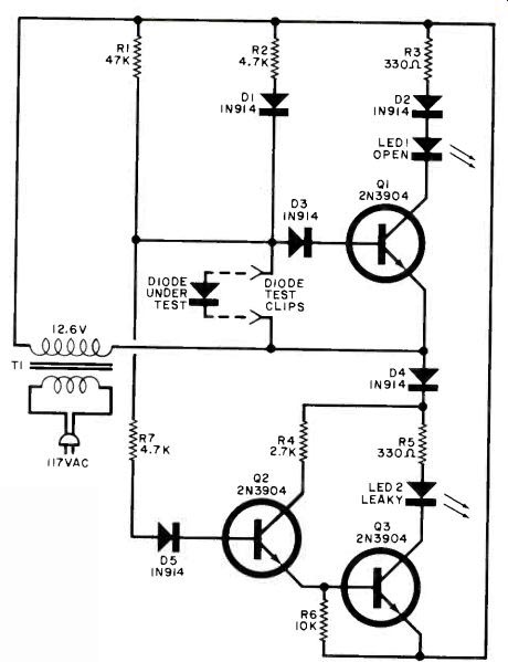
The peak reverse voltage is less than 18 volts and the peak forward current is less than 4 mA. With the values shown in Fig. 1, OPEN indicates a forward voltage drop in excess of 1.3 volts at 3 mA; and LEAKY indicates a reverse leakage current of about 0.05 mA at 16 volts.
How It Works. On one half cycle of the ac supply, the OPEN circuit is active (D1, D2, D3, R2, R3, Q1 and LED1). In this half cycle the upper ac line is positive. (D4 and D5 are reverse-biased to isolate the other part of the circuit.) Current, limited by R2, flows through D1 and the diode being tested. The voltage across the test diode is applied through D3 to the base of Q1.
If this voltage exceeds 1.3 V, Q1 turns on and sinks current through LED1, indicating high forward drop.
When the ac supply reverses, the lower part of Fig. 1 is active, with D1 and D2 reverse-biased to shut out the OPEN part of the circuit. Any reverse leakage current through the test diode lows through R1, creating a potential across it. This voltage is applied to the base of Q2 through R7 and D5. When his voltage exceeds about 2 volts, Q2 s energized, turning on Q3 and LED2.
Since the circuit uses a conventional 12-volt transformer, no dc supply is required and all switching is performed automatically at 60 Hz.
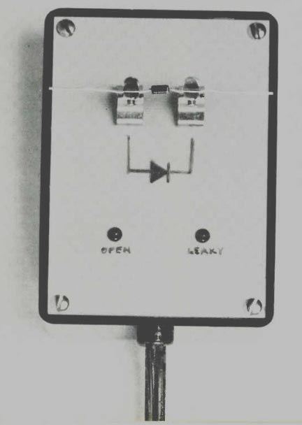
Construction. Although circuit layout is not critical and any type of construction can be used, a unique approach was used in the author's prototype as shown in the photographs.
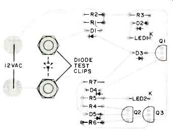
The pc board foil pattern shown in Fig. 2 can be used to make a board which has the components mounted on one side with the other side serving as the cover for the plastic case. The component holes are drilled only half-way into the board. The only holes drilled all the way through the board are those for mounting the LED's and the diode test clips. The other components are mounted by bending and cutting their leads so that they just fit on their pads. Solder must be applied quickly and properly to insure a good mechanical hold.
Transformer T1 can be attached to the bottom of the plastic case, with plastic foam insulation between the transformer and the components on the board. Use a grommet on the hole for the line cord in the side of the case.
Photo shows how curt,po,,o ids are mounted on pc board lritll the transformer in the bottom of the case with foam insulation.
Identify the LED's on the front of the pc board, and draw a diode symbol between the two test clips with the anode side going to the junction of D1 and R1.

Fig. 1. The "open" circuit operates when upper ac line is positive. "Leaky" circuit
operates when this line is negative. Both circuits test diode at line frequency.

Fig. 2. PC board can be used as case cover with component mounting as shown
at left.
PARTS LIST
D1 to DS--Silicon diode (IN914 or similar)
LED1, LED2--Red light emitting diode* Q1, Q2, Q3--Transistor (2N3904 or similar)
R1-47,000-ohm, 1/4-W, 5% resistor R2, R7-4700-ohm, 1/4-W, 5% resistor R3, R5-330-ohm, 1/4-W, 5% resistor* R4-2700-ohm, 1/4-W, 5% resistor R6-10,000-ohm, 1/4-W, 5% resistor T1-12.6-V, 100-mA transformer
*R3 and RS can be varied to change the brightness of the LED's.
Misc.--Diode test clips, plastic case (Harry Davis #220 or similar), line cord, grommet, mounting hardware, etc.
Checkout. Check the pc board for correct installation of components, and then apply power to the tester.
The OPEN indicator should come on.
Connect a diode that you know is good between the test clips. Note that both LED's are off. Remove the diode and connect a 100,000-ohm resistor between the test clips. Note that both LED's are on. Remove the resistor and connect two or three good diodes in series across the test clips. Only the OPEN LED should turn on.
Also see: