Here's a sensitive troubleshooting meter for phono cartridges, microphones, and PA systems
BY RALPH TENNY
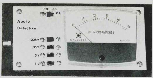
THE Audio Detective is a sensitive ac voltmeter which will prove to be especially useful in troubleshooting an audio system. On its lowest range (5 mV), it can be used to test microphones and many phono cartridges. It will also measure potentials up to 5 volts (50 volts, if a simple modification is made). The response of the meter is flat within 5% from 15 Hz to 20 kHz.
The instrument is battery-powered (1 mA current drain) and is conveniently small for portable use. A phono plug is used for the input and input resistance is 100,000 ohms.
Circuit Operation. The circuit made up of transistor Q1, R19, C7, and D8 is a regulated power supply which provides 14 volts for IC1 (Fig. 1). Due to the presence of C7, the supply turns on slowly to prevent capacitor charging currents on C2, C3, and C4 from damaging the meter. Diode D7 protects the circuit from an accidental reversal of battery polarity.
The network consisting of R1, R2, and R3 sets the quiescent operating level of 7 volts at the output of IC1A. The dc interstage coupling through R4, R7, and R10 maintains this voltage at the outputs of the three following stages. The high input impedance at the noninverting (+) input of IC1A prevents loading of the input attenuator. Diodes D5 and D6, in conjunction with R18, are used to protect IC1 from excessively high input voltages, which might damage it.
Sections B and C of IC1 amplify the audio signal from section A with stage gains determined by the ratios of R5 to R6 and R8 to R9. Capacitors C2 and C3 couple the ac currents to the common bus so that the ac output of each stage swings about the 7-volt dc operating level.
Section D of IC1 is a precision rectifier and meter driver. The parallel combination of R11 and R13 establishes the gain of the stage. Varying the value of R13 calibrates the meter so that the meter current is 50 microamperes (full scale) when 5 mV is applied to the (+) input of IC1A. Resistor R12 and the combination of C5 and C6 shunt R11 at the higher audio frequencies to adjust the frequency response near 20 kHz.
Construction. Circuit layout is not critical so perforated board and mounting clips or a printed circuit board can be used. It is advisable to use a socket for IC1 to avoid possible heat damage during soldering.
Because of the low signal levels required by the measuring circuit, a single common bus is used. Tie all the circuit ground points to this bus and connect the bus to the case at only one point--preferably at the ground lug of J1. If J1 is mounted on a metal panel, make no other connections to the metal portion.
Whatever the layout and case, the checkout of the circuit will be easier if one section is wired and tested before going to the next. Start with section D of the IC and the meter circuit. Since charging currents in C2, C3, and C4 will cause current surges in the meter, the operating voltage must be applied slowly to avoid any possibility of meter damage. The test circuit shown in Fig. 2A is used to do this. The dc operating power can be a battery or power supply between 12 and 15 volts dc. Be sure the potentiometer is at the zero position before turning on the power. The signal generator should be capable of delivering a low-distortion, 1-kHz sine wave which can be set to zero output.
When wiring this first section, connect R10 temporarily to point A of the test circuit. Turn on the power and slowly adjust the test circuit potentiometer to bring the voltage to between 12 and 15. As the voltage is increased, the meter action will be erratic and move upscale.
When the power is fully on, the meter should settle back to zero.
Turn up the audio generator connected to the test circuit. As the generator output is increased, the meter will reach full scale when the generator is delivering 0.3 volt rms. Once this section is working properly, reduce the test circuit voltage and audio generator output to zero and remove the connection to R10.
Now wire up the rest of the circuit (sections A, B, and C of IC1). Perform the above test again and note that the inputs to sections A and B are 5 mV rms for a full-scale meter indication.
=========
PARTS LIST
B1, B2-9-volt battery C1-0.1-1.F, 50-V ceramic capacitor C2, C3-100-µF, 25-V electrolytic capacitor C4-22-µF, 25-V electrolytic capacitor C5-100-pF capacitor C6-47-pF capacitor (see text)
C7-45-µF, 25-V electrolytic capacitor C8-225-µF, 25-V electrolytic capacitor D1 to D7-1N4148 diode D8-15-V zener diode (HEP Z0225)
IC1-Integrated circuit (National LM324)
.11-Standard phono jack (RCA) M 1-0.50-µA meter (Calectro D1-910 or similar)
Q1-2N5449 or TIS98 transistor Following resistors are 1/4-W: IC1=LM324
R1 ,R2-47,000 ohms R3-1.2 megohms R4, R7, R10-1000 ohms R5, R8, R18-10,000 ohms R6, R9-1500 ohms R 11,R 12-5600 ohms R 13,R 19-(see text)
R14-91,000 ohms (see text)
R 15-9100 ohms (see text)
R16-910 ohms (see text)
R17-100 ohms (see text)
S1 to S5--Spdt switch
Misc.--Suitable chassis (Calectro H4-722), battery holder, mounting hardware, etc.
==========
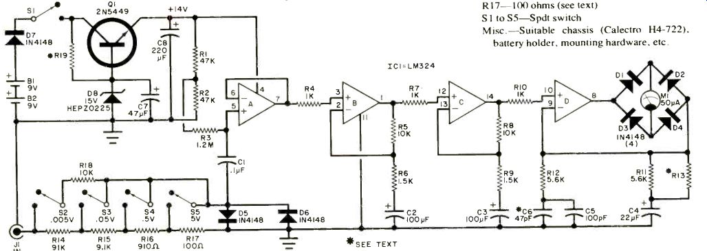
Fig. 1. The first three op amps in IC1 form a sensitive ac amplifier and
the fourth drives the meter.
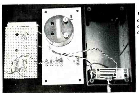
----- View of interior of the Audio Detective as assembled in the
author's prototype.
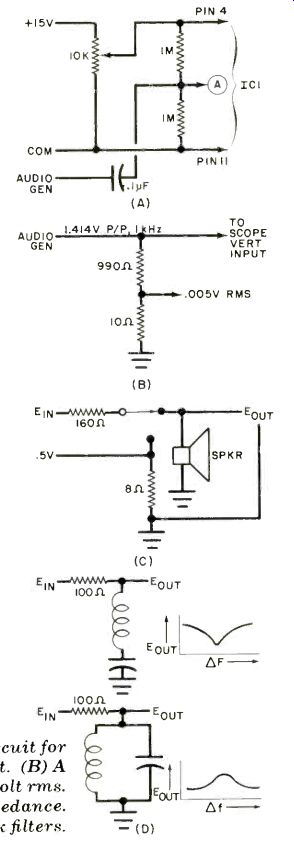
Fig. 2. (A) Test circuit for stage-by-stage checkout. (B) A source of 0.005-volt
rms.
(C) Measuring speaker impedance. (D) How to check filters.
Assemble the power supply portion, using 150,000 ohms for R19. The time constant for R19 and C7 determines how fast the operating power comes up.
Select the value of R19 so that the circuit comes into full operation without violently "pegging" the meter. On the prototype, the meter settled back to zero about seven seconds after power was turned on.
Complete the assembly, wiring up the input attenuator. The resistors used in the attenuator can be conventional 5% types or they can be selected with a resistance bridge to be as close to the stated values as possible. The more accurate the resistor value, the more accurate the meter readings.
Turn on the power and apply an audio signal of about 5 mV rms at 1 kHz to J1 to get a full-scale reading on the meter.
When the next higher scale is switched in, the meter should indicate about 1/10 of full scale. Bring the meter to full scale by adjusting the audio source. Switch to the next higher scale (0.5 V) and note that the meter goes down to 1/10 of full scale. Repeat the adjustment and check the next range.
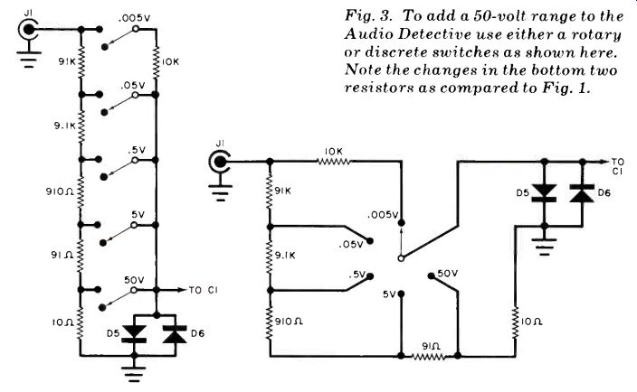
Fig. 3. To add a 50-volt range to the Audio Detective use either a rotary
or discrete switches as shown here. Note the changes in the bottom
two resistors as compared to Fig. 1.
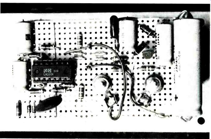
------ Components assembled on the perforated board.
Either a laboratory calibration standard or a dc-coupled scope can be used for final calibration and frequency-response checking. If a scope is used, start with the calibration. Use a new flashlight battery (1.55 volts). Set the scope to 0.2 volt per division, and connect the battery to the scope vertical input. Adjust the scope vertical gain until the trace is 7 3/4 divisions from its zero position. If the scope has a different vertical range, use a range that produces a nearly full-scale deflection.
Carefully select the two resistance values shown in Fig. 2B and apply 1.414 volts peak-to-peak at 1 kHz as shown.
Connect the 0.005-volt rms output of this voltage divider to J1 of the Audio Detective, with the attenuator set for 0.005 V. Select a value for R13 that will give a full-scale meter indication. Keeping the output of the audio generator at this constant level, reduce the frequency until the meter indicates 0.0047 volt. The generator frequency should be lower than 20 Hz. If a slower roll-off is desired, increase the value of Cl. In this way, it is possible to bring the flat response down to 10 Hz. If a lower frequency is required, it is necessary to increase the values of C2, C3, C4, and C7, and lower the value of R19.
With the output of the audio generator held at 1.414 V peak-to-peak, increase the generator frequency to 20 kHz. If the meter indicates too low a value, the high-frequency response must be adjusted. This is done by adding more capacitance across C6. Be careful not to add too much compensation, which will result in a "hump" near the 20-kHz point.
Like all ac voltmeters, the Audio Detective will respond to almost any waveform. However, it is calibrated for a sine wave and other waveforms will produce erroneous meter readings. For example, a 9-volt peak-to-peak sine wave will read 3.2 V on the Audio Detective. A 9-volt square wave would show up as 5 volts. However, as long as the waveform remains the same, relative measurements of nonsinusoidal waveforms can be made.
Uses. The Audio Detective can be used to troubleshoot a PA system. Plug the microphone to be used into J1 (with the correct adapter) and speak into the mike. A dynamic mike should have an output of about 1 mV, and a condenser (electret) mike should generate between 4 and 5 mV. The Audio Detective can then be connected to the mixer output to test that stage. The procedure is continued through the audio system to the speaker outputs. The signal level will get progressively higher. At the speaker outputs, five volts on an eight-ohm line indicates just over three watts.
To determine the gain of an amplifier, use the Audio Detective to measure the input and output voltages. The gain is simply the output voltage divided by the input.
To test the frequency response of a tape recorder, apply a 1-kHz tone to the recorder's auxiliary input and select a level that gives a comfortable playback volume with the volume control set at midrange. Record several different frequencies at this same level. Terminate the external speaker output with an 8-ohm resistor and monitor the voltage generated across the resistor at each frequency. (For component tape decks, monitor the line output unterminated.) Plot the output voltage as a function of frequency.
To determine speaker impedance, use the circuit shown in Fig. 2C. Select E, so that 0.5 volt is generated across the 8-ohm resistor. Switch to the speaker and measure Eot. The speaker impedance at that frequency is (Zot/0.5) x 8. For example, if Zot is 0.45 volt, the speaker impedance is (0.45/0.5) x 8 or 7.2 ohms.
You can check the frequency response of a filter by using the circuit in Fig. 2D. Holding the input constant, vary the frequency and plot Eot as a function of frequency. Figure 2D also shows typical response curves for both series and parallel resonant circuits.
Modifications. The schematic in Fig. 1 shows the input attenuator spanning four ranges from 0.005 to 5 volts. If you want to extend the upper limit, use the attenuator shown in Fig. 3. Two versions are shown-one using five slide switches and one a rotary switch. Either will extend the range to 50 volts.
Also see:
Link | --Automatic Diode Checker
Build a Direct Reading Logic Probe