Rapid circuit assembly and alteration methods using perforated board.
BY ADOLPH MANGIERI
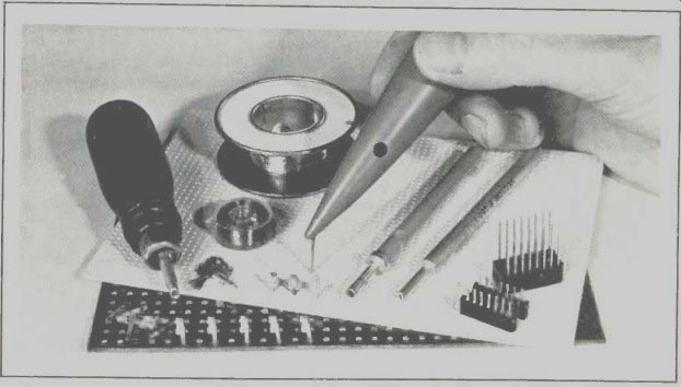
--------- Useful tools (left to right) pin insertion tool wire (un)wrapping
tool.
MOST electronic projects are best assembled on either printed circuit or perforated board.
Both types have advantages and disadvantages which should be considered before starting a project. The pc board permits compact assemblies but impedes experimentation and circuit alterations. Perf board, on the other hand, permits rapid assembly and easy circuit alterations but tends to take up more room for the same circuit. With few exceptions, any project you can build on a pc board can also be assembled on perf board.
Perf board construction has another important advantage over the pc board. It eliminates the need for using chemicals and drilling holes.
This might be an important consideration if you're pressed for time arid want to get right to assembly after designing a layout. Needless to say, the perf board technique is a very attractive alternative to project assembly, especially if you do a lot of experimenting.
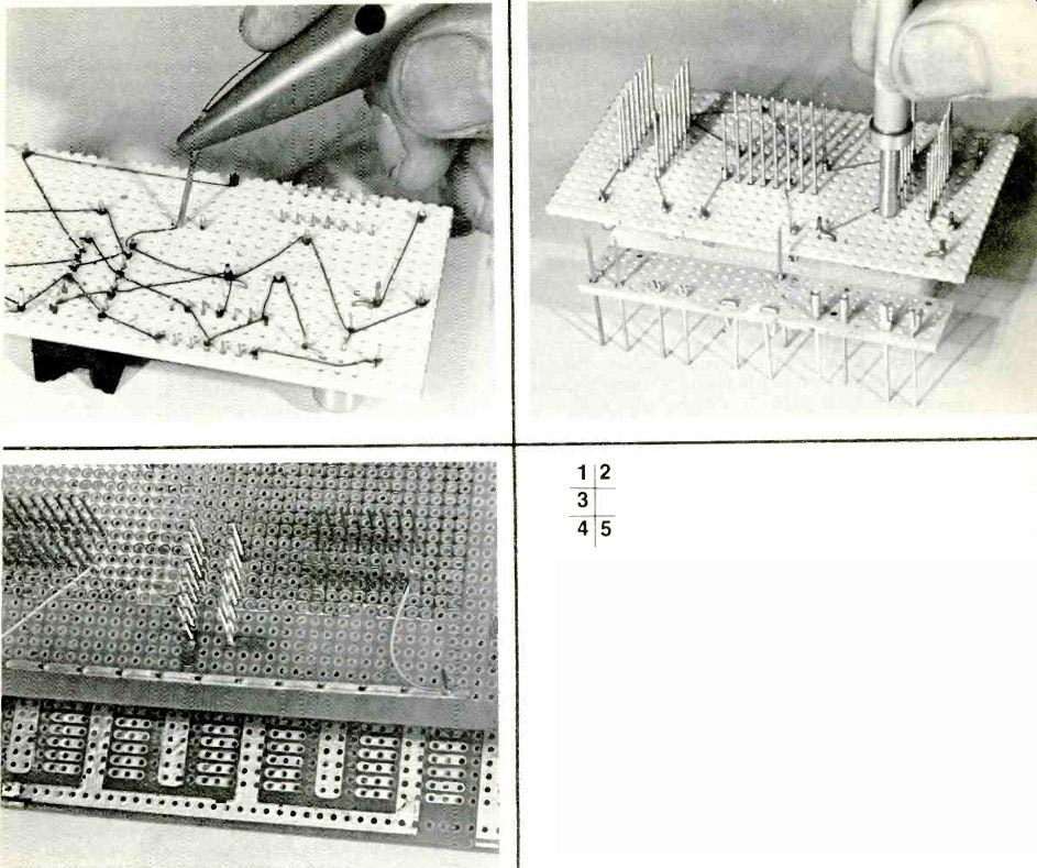
1. Wiring pencil wraps solder-through insulated wire on leads of resistors, IC's and transistors.
2. Wrapping tool used on solderless connections. Terminals in foreground facilitate wire wrapping.
3. Ground-plane board at top has terminals for ground connections. Below is interdigitated bus board.
4. Clad perf board requires cutting of circle pad for isolation of socket and board terminals.
5. Clad ground-plane board requires drilling and line and circle pad cutting. Pad cutter at right.
Perf Board Materials. The first step in working with pert boards is to familiarize yourself with the various types of boards, tools, and hardware available. Perf boards are letter-coded according to patterns, sizes, and spacing of holes. Furthermore, you have a choice of XXX phenolic, paper epoxy, and epoxy fiberglass material and unclad (plain) and clad blanks. Add to this list a choice of board thicknesses.
The Table lists the most popular perf board configurations (from two typical sources) according to letter code, the various push-in terminals and insertion tools, and pre-punched bus strips to be used with each. It is obvious that you can choose the materials to meet the requirements for your project. For example, use P-pattern board for IC's in dual in-line packages (DIP's) and either Por G-pattern board for round (TO-5) transistors. A less desirable alternative would be to use F-pattern board and drill extra holes as necessary. For heavy-weight projects, such as power supplies, you can use A-pattern board with extra thickness and the large No. T9.4 push-in terminals. (For general use, 1/16"-thick board is an excellent choice, while 3/32"-thick board is recommended for the majority of the heavier duty jobs.) Bus strips are flat, pre-punched and tinned and made of copper for use as power supply and common buses.
They eliminate wiring complexity and reduce the chance of ground loops that create circuit instabilities. Low-cost solder pin insertion tools permit you to install pins safely and speedily.
Accommodating most semiconductor devices (including IC's) and accepting an almost endless variety of board pins, the 1/16" thick P-pattern board will prove to be the most versatile for many projects.
Conventional Wiring Method. As is the case when doing pc work, careful layout planning will be rewarded with neater perf board assemblies and error-free wiring. You can design a parts layout and wiring guide for perf board with the aid of the grid paper available for most board patterns or even ordinary graph paper. To a large extent, your parts layout will follow the schematic diagram for your project.
Of course, you'll have to trial-fit the components on the board, making allowance for the pattern and spacing of the holes.
Once you know how a board is to be laid out and wired, you can install push-in terminals, transistor and IC sockets, and power and common buses. If you choose to omit bus strips, use 20-gauge (or heavier) solid bare hookup wire in their place.
When making interconnections, 28-gauge solid wire is suggested for easy handling and manipulation with tools. Wherever possible, use bare wire; but if you must make crossover connections, switch to insulated wire.
Use 24- or 26-gauge insulated stranded hookup wire between the board assembly and off-the-board components. When your project includes DIP (dual in-line package) IC's, avoid confusion by labeling pin 1 of each. Better yet, use E-Z-Code self-sticking pin number marking strips.
Fitting wire with long nose pliers can prove to be a trying task, particularly when using P-pattern board and DIP sockets. You can save a great deal of time and avoid much frustration by using a manual tool to wrap the wire on a terminal (such as the Vector No. P160-2A or similar). This tool neatly forms a tight wrap on either socket solder tabs, No. T42.1 flea-clip tails, component lead ends, or directly on DIP IC pins. These aren't true Wire Wraps", which means that every connection must also be soldered to assure good mechanical and electrical bonds.
After wiring a project, it's always good practice to check for errors before applying power. Look for reversed installation of diodes, electrolytic capacitors, LED's, etc.; IC's and transistors plugged in backwards; and transposed connections to battery clips and holders.
"Pencil Wiring." Recently, a new approach to wiring perf board assemblies has been introduced. Vector's new Model P173 wiring pencil promises to become a very popular tool for pert board work. Applied Manufacturing of Texas has a similar tool for making Solder Wraps''. The wiring pencil eliminates having to cut wires to size and strip away insulation. The pencil dispenses and wraps 36-gauge solder-through insulated solid wire around any size post or terminal. Much faster than point-to-point wiring, pencil wiring permits you to interconnect a number of terminals with an unbroken length of wire. Once the wire is wrapped around a terminal, you apply heat directly to the joint. The insulation immediately vaporizes to allow you to flow solder into the connection. A very important advantage of pencil wiring is that it permits you to omit all sockets and most solder terminals.
As shown in Fig. 1, the wiring pencil feeds the wire from a bobbin containing 250' (76.2 m) of wire through the tool's barrel, out one of two holes, and down through a hollow "needle." Wire feed and tension are controlled by finger pressure on the wire where it comes out of the hole in the body of the tool. (The two holes are provided so that either right or left handed people can use the tool.) At the end of a run, you simply twist the pencil, and the point of the needle quickly and neatly clips the wire.
Sockets and solder clips can be omitted during assembly by using the pencil to wire directly to protruding leads and lugs. To use this technique, however, the components must be staked to the board (leads bent to mechanically secure parts in place) as shown in Fig. 1. You can use long-nose pliers for staking, but Vector's No. P174 staking tool makes the job easier. Components can also be cemented to the board with a quick-set adhesive, and eyelets make excellent solderable anchors for problem components.
You can avoid having to stake components by isolating circular pads on copper-clad pert board (discussed later under Ground Plane Methods). Solder upright ends of component leads and socket tabs to the circle pads to anchor the parts in place. Use pre-punched bus strips on the top of the board (unclad side) for the power buses. For feed-throughs, use either No. T42-1 flea clips, double-ended No. K31C round-shank pins inserted with a No. P133-A tool, or the single-ended No. T50 round-shank series shorting pin. Using clad perf board, you can dispense with bus strips altogether by isolating strips of copper (also discussed later). Here are a few useful hints when working with a wiring pencil. Form your wraps slightly away from the board's surface to avoid marring the board with heat during soldering. Use a soldering pencil that has a tip temperature of at least 650° F (343° C) and "wet" the tip with solder before applying heat to a joint or wrap. To prevent wire breakage, dress the wire close to the board and secure lengthy runs with drops of quick-drying cement.
Isolated round-shank pins make good pivot points for routing wires around obstacles. Alternatively, you can use a No. P179WS plastic wire spacer for grouping wires in a bundle. In a pinch, you can use 30-gauge bare solid wire, at least for ground returns.
Wire Wrapping. Wrapping wires around terminals, either with or without solder, offers wiring flexibility to permit rapid circuit changes. The standard wrapped connection consists of six to eight turns of wire applied under tension to square, sharp-edged wrap posts. The modified wrap, or anti-vibration wrap for extreme conditions, includes an additional one or two turns of insulated wire at the start of the wrap.
If you plan to use this technique, you'll need an efficient and easy-to-load manual wrapping tool, such as Vector's No. P160-2A. The No. P160-1A is an unwrapping tool for easy removal of wrapped connections. The preferable wire size for wrapping is 28-gauge bare or Kynar insulated (Vector No.'s 2323A-28-3 or 2323A-28-4). Pre-cut and pre-stripped wire (Cambion sells a 30-gauge No. 601-2515 wire kit) will speed assembly but, unless trimmed as you go, will leave you with a maze of slack wires.
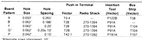
PERFORATED BOARD CONFIGURATIONS
You can assemble an entire project using wrapped wire and the appropriate pins as shown in Fig. 2. From left to right, the pins shown include pairs of Vector No.'s. T46-3 double-ended wrap posts that should be inserted with tool No. P133-A; T44 Miniwrap posts (No. A13 insertion tool); K32 J pins; R32 socket pins; and the versatile T49 Klipwrap post (No. P156 insertion tool). All this hardware is designed to fit P-pattern perf board.
It's difficult to insert a pin perpendicular to a board's surface unless you have an alignment block, such as Vector's No. MB45-20-062. It consists of 10 pieces of 1/16" P-pattern board glued in a stack. If you wish, you can make a small version from scrap board for use in tight places.
Forming perfect wrapped connections is a simple procedure, but it takes some practice to get the knack of handling the tool for positioning and dressing the wire. Use bare wire wherever possible. As with the wiring pencil, you can wrap a number of posts with an unbroken length of wire by passing the wire down through the handle of the wrapping tool.
Practice loading the wire until you can do it instinctively. The wrapping tool has a central hole that fits over the post. The end of the wire fits into a smaller off-center hole or tunnel near an index mark. If you're using 28-gauge insulated wire, strip away 3/4" (about 2 cm) of insulation. Hold the tool about horizontal with its index mark up. Catch the end of the wire in the cross slot of the tool's recessed tip near the index mark and insert into the wire tunnel. If the wire bottoms out before accepting the entire stripped end, it's in the wrap post hole. You'll have to withdraw and try again. Once the wire is properly inserted, anchor it in place by withdrawing half way, bend the wire about 30°, and push home before making the final right-angle bend.
Projects requiring numerous wrapping card sockets are best assembled with a cordless power wrapper, such as Vector's No. P160-4, which accepts the No. P160-2A manual wrapper.
Ground Plane Methods. Having a large area of copper at ground potential, the ground plane affords minimum ground circuit impedance and permits the shortest possible connections to ground. This not only eliminates instability in broadband vhf amplifiers, it also minimizes noise and ringing in digital circuits. To achieve these benefits, keep lead lengths as short as possible and inputs and outputs well separated.
Beginning with P-pattern etched ground-plane board (Vector No. 3677-7), the copper surrounding the board holes is pre-etched, leaving circles of insulation around the holes (Fig. 3). Primarily intended for wire wrapping, this board can also be used with any other wiring method. To ground a wrap post to the ground plane, push a self-fastening No. T112-1 bus link onto the post with a No. P133A insertion tool and solder the tab to the plane.
With all ground-plane wiring methods, it is best to run insulated wire right up to the pin to avoid short circuits. Better yet, wrap a turn of insulated wire on the pin nearest the board. This is easily accomplished with the No. P160-2A wrapping tool by pushing a bit of wire insulation into the recessed tip before bending the wire at a right angle. Alternatively, you can bend the wire on the insulation before loading the wrapping tool.
(You can also use this tip to form anti-vibration-wrapped connections.) Etched pad boards that have generous inter-digitized ground and supply buses (Vector No. 3677-6) closely approximate the full-ground type plane.
Assign ground to buses passing between socket pads. By jumpering common-ground and supply buses, a further reduction in ground and supply bus impedance can be effected.
The pad board lends itself well to any wiring scheme. A manual line cutting chisel (Vector No. P139) permits you to safely cut through a bus or pad to isolate it.
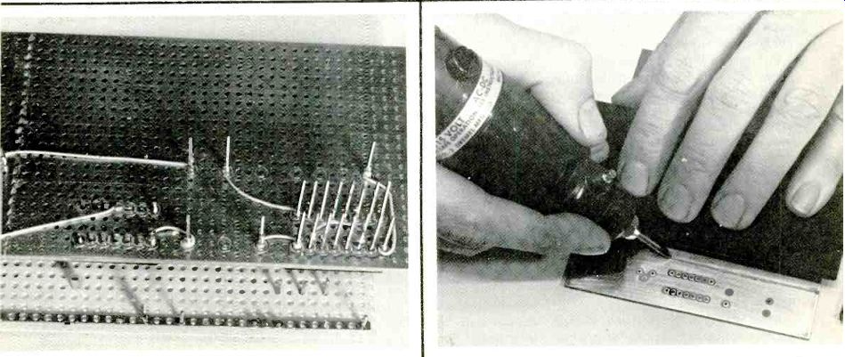
Fully clad (one side only) perf board can be used for ground planes (Fig. 4). For P-pattern board, you'll need a circle pad cutter, such as Vector's No. P138C tool. Cut circle pads at all pin locations where the circuit must be isolated from ground. Grounded points should not be isolated. To avoid rapid cutter wear and tearing out pads, use a low drilling speed. (Hint: With high-speed power tools, like those made by Dremel under the "Moto" brand name, use a solid-state speed control set for about 45 volts ac.) You can avoid drilling too deeply into the board by backing the board with a metal plate to serve as a stop for the cutter bit's pilot pin. If the cut is too shallow and doesn't remove enough copper, place an index card between board and plate.
Accidents are bound to occur. So, if you do tear out a pad, install a No. T102 or T103 eyelet with flange on the clad side of the board. Pads not required for use as anchors or supports are best removed with an Xacto knife to reduce the chance of solder bridging or wiring shorts to ground. If you capture a pad within the cutter, remove it with a large needle or awl. Before you start wiring a circuit, check all pads with a magnifying glass and re-drill any that have copper bridges to ground.
Use No. T107 bus strips on the unclad (top) side of the board, or section off a strip of copper on the bottom of the board using an electric line cutter.
A tungsten carbide router bit (Dremel No. 9909 or Vector No. P141A) chucked into a Dremel Moto tool will make short work of line cutting, as shown in Fig. 5.
You can make a line cutting guide by cementing a 4"L x 1 1/2"W x 1/16"T (10.2x3.8 cmx1.6 mm) piece of insulation board to a block of 1/4" (6.4-mm) thick plywood, overlapping it by 1/4" along the long dimension. Cement a sheet of nonskid rubber to the bottom of the plywood. To use the block, place the guide along the line to be cut and hold the cutting tool at about a 45° angle to the board's surface and held firmly against the guide edge. Don't try to cut the line in one pass; make several light passes until all copper is removed along the line. A prepackaged line cutting kit containing a Dremel Model 260 drill, router bit, and several accessories is available from Vector as the No. P141B kit.
Also see: