BY JOSEPH J. CARR
Practical, low-cost references for checking accuracy of test instruments.
PRECISION voltage and current references are routinely used in a variety of applications. These references are useful for calibrating vertical deflection factors of oscilloscopes and indications of voltmeters and ammeters, for example. They also find use in data conversion, where almost all analog-to-digital (A/D) and digital-to-analog (D/A) converters employ a reference voltage or current. Regulated dc power supplies that employ error amplifiers also require precision voltage references. (The output of an error amplifier controls regulator action, which is, in turn, controlled by the difference between actual output--supply and reference voltages.) Precision references were quite costly only a few years ago. Now, owing to low-cost ICs, good precision references can be built at low cost.
Before we examine IC voltage and current references in detail, let us review some of the older methods for obtaining references so that principles will be more readily understood.
Zener Diode. A simple circuit in which a zener diode is the regulator element is shown in Fig. 1. Also shown is a typical zener-diode characteristic curve. In the V+ forward-bias region, the zener diode behaves much like any other silicon diode that conducts a +I forward-current when V+ is greater than about 0.6 volt.
In the V reverse-bias direction, however, there is a distinct difference between zener and conventional silicon-diode behavior.
Normally, a conventional silicon diode does not conduct current when reverse biased (except when applied reverse-bias voltage exceeds the diode's rated PIV). A zener diode acts quite conventionally between 0 and some V value called the "zener potential," or Vz.
When V reaches or exceeds Vz, the diode breaks over and begins to conduct a reverse current.
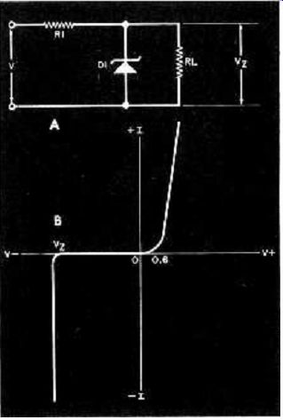
Fig. 1. Zener-diode reference supply. The circuit is shown at A. while
the characteristic curve is below at B. The fact that the zener voltage
is dependent on temperature must he kept in mind in circuit design.
As long as ambient temperature is held constant, Vz will also be constant.
Bear in mind that the Vz value is different for different types of zener diodes and that even then there is a "nominal" voltage. This means that a large number of identical zener diodes will have values that cluster closely around Vz.
When you build a precision power supply or reference source, you must keep either of two considerations in mind. You must provide a constant-temperature environment or use temperature-compensated circuitry. Then either hand-select the zener diode or provide a means for adjusting the output of the circuit so you can compensate for incorrect zener potentials.
Unfortunately, temperature cannot always be maintained constant in practical circuits, especially where cost is a factor. An attempt at solving temperature dependence by using several zener diodes to produce the desired Vo output voltage is shown in Fig. 2. The actual Vz value for the different diodes will vary with changes in temperature, but if all diodes used are in the same thermal environment, any temperature change affects all diodes equally. The output voltage, which is the differential voltage between the two points shown, remains constant regardless of temperature changes.
Output potential Vo = (V5 + V6)-V3.
A problem with circuits such as that shown in Fig. 2 is that the output voltage is not ground referenced. If a ground--referenced potential is required, Vo should be applied across the differential inputs of an operational amplifier. The output potential from the op amp would then be the product of op-amp gain Av and output voltage Vo, or Vo x Av.
Opamps are frequently used to buffer zener-diode regulators and allow more precise setting of actual output voltage.
The circuit usually used for reference sources is shown in Fig. 3. You should recognize this as a special case of a noninverting gain-follower circuit in which zener diode D1 is used to set the potential applied to the noninverting input. Voltage gain for this circuit is 1 + Ra/R1.
Therefore, Vo = Vz (1 + Ra /R1).
Feedback resistor Ra is actually fixed resistor R2 and potentiometer R3.
If R3 is a 10-turn (or more) trimmer pot and has a total resistance of only 10% to 20% of RA, Vo can be set precisely.
The circuit in Fig. 3 is used for moderate-precision applications. It still requires a constant-temperature environment to maintain Vo stability. Both zener diode and op amp may tend to drift with changes in temperature. Several commercial voltage-reference standards are available in which circuits such as that shown in Fig. 3 are installed in proportional control temperature ovens.
Precision IC References. IC voltage references allow you to build simple voltage and current references that perform as well as all but the best discrete references previously available.
National's LM199 (and companion LM299 and LM399), shown in Fig. 4, contains a zener diode, whose Vz is nominally 6.95 volts, inside an IC that also has a built-in conductor heater.
(The zener diode is buried in the same semiconductor die as the heater circuitry. This yields lower-noise operation and provides thermal stability.) Ordinarily, zener potentials can change as much as 5 mV/°C, but in temperature-controlled LM199s, drift is limited to microvolts.
Although the LM199 is rated to have an initial stability of ±2%of rated voltage, its stability is very good. Long-term stability is rated at 20 ppm and short-term, as low as 1 ppm. Use of the thermal insulator cap supplied with the LM199 is highly recommended.
In normal operation, the LM199 is used in the same manner as any other zener diode, provided the heater terminals are connected across a 9-to-40-volt dc power supply. Pins 2 and 4 are usually grounded to keep the internal substrate reverse biased. Pin 3 connects to the dc power supply, while zener cathode pin 1 connects into the circuit. Circuits like that shown in Fig. 3 are often used with the LM199.
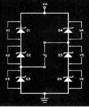
Fig. 2. Several zener diodes may be used in an attempt to stabilize
variations in circuit operation due to changes in temperature.
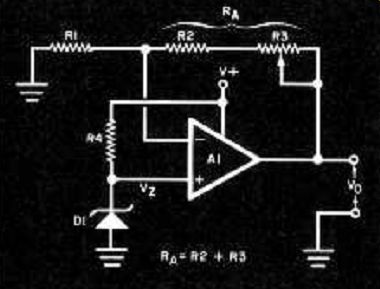
Fig. 3. By adjusting the gain of the opamp (by varying R3), the output
voltage can he trimmed to a precise value.
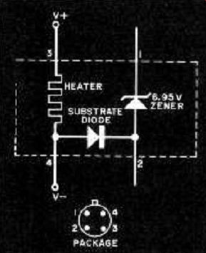
Fig. 4. The LM 199 temperature-stabilized zener diode uses an on-chip
heater.
Another precision device that can be treated as if it were a zener diode is the band-gap regulator from Ferranti Electric, Inc. (Semiconductor Products Div., 87 Modular Ave., Commack, NY 11725). Versions in either 2.45 or 1.26 volts are available. Construction of these regulators is shown in Fig. 5. The internal circuit is basically a current-boosted op amp with a band-gap reference diode at the noninverting input. These are two-terminal devices that can be used as if they were ordinary zener diodes.
The Ferranti ZN404 and ZN458A/B are 2.45-volt regulators. They differ as to initial calibration tolerance and thermal drift. While all are better than ordinary zener diodes, the ZN458B is the best in the line. (The ZN423 is a 1.26-volt version of the ZN458B.) All three Ferranti devices sink up to 120 mA and have a 2-to-120-mA operating range.
Long-term stability of the Ferranti regulators can approach 10 ppm/1000 hours, while temperature coefficient is rated at 0.003%. Current-limiting resistor R's value is:
[V+ -VREF)/I_REF
(R = resistance in kilohms; V+ = supply potential; VREF = nominal rated reference potential of the device; and IIREF = device current).
As in all precision voltage reference supplies, the resistor should have a low temperature coefficient. In most cases, this means use of a wirewound or metal--film precision resistor. Fortunately, actual resistance value is not too critical. So, if Rs calculated value is an odd number, the nearest standard value can be used.
This changes the IREF value but not the output voltage. As an example, if a ZN458B had to operate from a +12-volt supply and pass 10 mA, Rs calculated value would be 955 ohms. Since this is a difficult value to obtain, you can substitute a 1000 -ohm resistor, which changes the current from 10 to 9.6 mA. Precision Monolithics' REF -01 and -02 shown in Fig. 6 produce output potentials of 10.00 and 5.00 volts, respectively. The untrimmed output from the REF-01, with pin 5 open, is in the 9.9- to -10.1-volt range. With trimming, it can be set to 10.00 volts ±300 mV, which is a 3% range. In most applications, the output can be trimmed to exactly 10.000 volts. Trimmed, the temperature coefficient is 0.7 ppm/°C. The REF-01 can supply up to 20 mA of current and operates from supplies in the +12- to +40-volt range. A large VIN
Vo difference in any regulator is undesirable, however, because it increases device power dissipation and, hence, temperature.
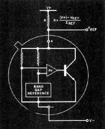
Fig. 5. The Ferranti Electric voltage stabilizers ZN404. ZN423T, and
ZN458A/B are used as two-terminal devices.
The 5-volt REF-02 has a 4.975-to -5.025-volt output. It can be trimmed to 5.00 volts ±150 mV (3% range). Input range is 7 to 40 volts, but, once again, avoid high input/output voltage differentials. The REF-02 differs from the REF-01 in that it has a temperature output terminal. Use of an internal band-gap regulator produces an output at pin 3 of approximately 2.1 mV/°C. This allows the REF-02 to be used as a sensor in a simple electronic thermometer project.
The standard thermometer circuit in which the REF-02 is used is a differential operational amplifier. The 5.00-volt output from the REF-02 goes to the inverting input, while the pin-3 output connects to the noninverting (-) input of the op amp. Op-amp gain can be set so the output voltage is numerically the same as the temperature. This type of thermometer is easy to build and can be used to drive a digital voltmeter to obtain a temperature display. Measurement is linear over the -55° to +125° C range of the REF-02, which makes the REF-02 an excellent replacement for nonlinear thermistors.
A similar reference source IC is offered by Motorola as the MC1404X and MC1504X devices. These use the same pin-outs as the REF-02 but are housed in 8-pin mini-DIP packages instead of the 8-pin metal can of the REF-02. These devices are available in three different standard output voltages: 10 volts (MC1404U10), 6.25 (MC1404J6), and 5 volts (MC1404U5). Current References. A reference current, rather than a reference voltage, is required in some cases. If load impedance remains constant, a reference current can be generated by applying a known reference voltage to a fixed low-temperature-coefficient resistor. In cases where load impedance may vary, a dynamic regulator circuit that compensates for these changes must be used.
Several such circuits are shown below in Fig. 7.
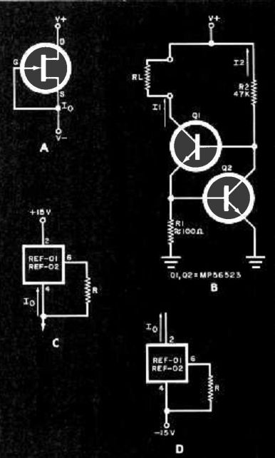
Fig. 7. Constant current sources: (A): using a JFET. (B) bipolar transistors.
(C) REF-01 as a current source, and (D) REF-01 as a current sink.
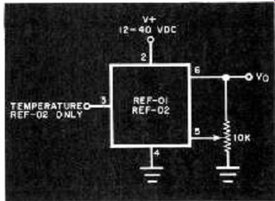
Fig. 6. The Precision Monolithics. Inc. REF-02 reference has a temperature/
voltage output on pin 3, for use as an electronic thermometer sensor.
The simplest constant-current source, shown in Fig. 7A, consists of a junction FET with its gate and source leads connected together. Several manufacturers offer constant-current "diodes" that are little more than a two-terminal package containing a JFET connected as in Fig. 7A. The problem with this type of arrangement, however, is that the current value is determined by the JFET's characteristics. Attempts at varying current by placing a potentiometer in series with the source usually reduce regulation.
A circuit in which two bipolar transistors are used to sink a constant current is shown in Fig. 7B. This circuit was designed around Motorola MPS6523 transistors, but thermal tracking might be improved if a dual npn transistor, such as the MAT-01, is used. Output current 11 is approximately 0.6/R1. Current 12 is variable but is best set to about 0.1 x 11.
The REF-01 and -02 voltage regulators can also be used to produce a constant-current source and are capable of either sinking or sourcing current, depending on circuit configuration. Both circuits are the same, except for polarity (Fig. 7C and D, respectively). In the case where a REF-01 is used, output current is (10/R) + 1. Since current is usually in milliamperes, it is simplest to express R in kilohms to avoid having to convert the decimal number obtained from the equation.
Conclusion. Our aim in this article was to introduce you to the various modern devices that can be used to obtain precision current and voltage references and regulators at low cost. Precision reference/regulators need no longer be confined to the laboratory.
Source: (Popular Electronics Electronic Experimenter's Handbook (1982)
Also see: Perform Complete Impedance Measurements With This R-F Bridge