BY FRAN HOFFART
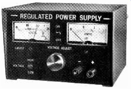
Adjustable (1 1/4 to 33 volts) supply delivers up to 1.5 amperes with excellent regulation.
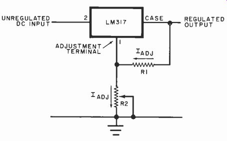
Fig. 1. Basic circuit showing the operation of the LM317 regulator integrated
circuit.
ONE ITEM that belongs on every experimenter's work bench is a source of clean, regulated dc. The ideal hobbyist supply would be relatively inexpensive, easily built, adjustable over a fairly wide range of output voltage, and capable of sourcing an ampere or more of dc. In addition, it would have a high degree of line and load regulation and contain such protection as automatic current limiting, maximum power limiting, and thermal shutdown.
The project presented here satisfies these requirements handily. It is built around an LM317, a monolithic variable--voltage regulator IC that can provide an output voltage from 1.25 to 40 volts. The supply can generate output currents up to 1.5 amperes at 1.25 to 33 volts. It has a low parts count and is rugged enough to withstand the abuse to which most bench supplies are subjected at one time or another.
Before we examine the power supply circuit, let's first look at the LM317 variable-voltage regulator IC. Because this chip is the essence of the supply, a prior understanding of its operation will simplify our later discussion of the power supply as a whole.
The LM317 Regulator IC. Shown in Fig. 1 is a simple schematic which illustrates the basic operation of the LM317.
The integrated circuit keeps the voltage drop between the output terminal (the case of the regulator, which is housed in a TO-3 package) and the adjustment terminal (Pin 1) a constant 1.25 volts. In practice, resistor R1 is connected between these two terminals, thereby setting up a constant adjustment current.
The magnitude of this current and the setting of potentiometer R2 determine the output voltage of the regulator.
If the adjustment current is sufficiently large, the output terminal is always 1.25 volts more positive than the adjustment terminal. Accordingly, setting the wiper of R2 so that the adjustment terminal of the IC is grounded causes the LM317 to act as a 1.25-volt regulator. Rotating the control shaft of R2 elevates the adjustment terminal above ground, simultaneously increasing the voltage at the output terminal.
Any voltage greater than 1.25 volts can be obtained at the output terminal simply by increasing the resistance between the adjustment terminal and ground. Although the manufacturer (National Semiconductor) rates the IC's maximum differential input-to-output voltage at 40 volts, the LM317 can be used to provide higher regulated voltages. However, such operation necessitates the inclusion of additional components to protect the regulator from excessive differential voltages.
Note that the LM317 has no ground terminal. This means that all quiescent operating current for the IC must flow through its output terminal, and necessitates that a minimum load current be established if the regulator is to function properly. Shown in Fig. 2 is a plot of the minimum operating current required against the differential input-to-output voltage. A convenient way to satisfy this minimum-load-current requirement is to select a value for the adjustment current that is suitably greater than the quiescent operating current of the IC. The internal design of the LM317 makes possible a wide variety of applications other than that of a series--pass voltage regulator. These include tracking pre-regulators, switching regulators, ac voltage regulators, two-terminal current regulators, and power regulators, to name just a few!
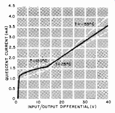
Fig. 2. Plots of minimum load currents vs. differential input-to-out
voltage.
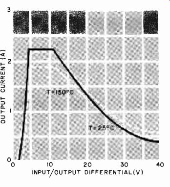
Fig. 3. The 20-watt safe-area curves for the LM317 regulator IC at three
operating temperatures.
Even more important than the inherent simplicity and flexibility of the three-terminal regulator IC is its ability to protect itself from practically every type of overload condition, thereby greatly increasing reliability. Output current is limited to 2.2 A to protect the IC as well as the power transformer and rectifier.
Safe-area protection limits the maximum power dissipated by the regulator to approximately 20 W, thus guarding the series-pass transistor located on the chip against a destructive secondary breakdown. The safe-area protection circuit decreases the maximum possible output current as the differential input-to-output voltage increases, thereby limiting the power dissipated to a safe value. A plot of output current limiting versus differential input-to-output voltage is shown in Fig. 3.
Thermal protection built into the LM 317 limits the maximum chip temperature to approximately 170°C. This protects the regulator from overheating, regardless of the type of overload or the amount of heat sinking provided. The temperature is sensed on the chip at a point near the series-pass transistor, enabling the regulator to shut down quickly if a potentially destructive overload condition occurs. Once the overload has been corrected and the chip cools down, the regulator turns back on and resumes normal operation.
All these protective circuits remain functional as long as an input-to-output differential of at least 2 volts exists, even if the adjustment terminal is accidentally disconnected from the rest of the circuit.
About the Circuit. The complete schematic of a 32-volt, 1.5-ampere bench power supply is shown in Fig. 4.
Using the LM317 voltage regulator greatly simplifies the design and construction of the supply but keeps performance and reliability at high levels.
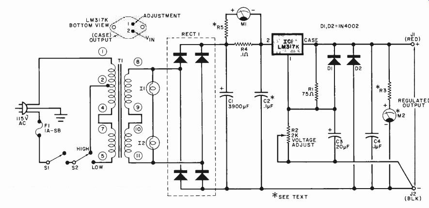
Fig. 4. Complete schematic of the precision power supply.
PARTS LIST
C1--3900-µF, 50-V electrolytic
C2, C4--0.1-µF disc ceramic (C2 optional)
C3--20-µF, 50-V electrolytic
D1, D2--1N4002
F1-1-A slow-blow fuse
IC1--LM317K TO-3 voltage regulator (National Semiconductor)
11,12-15-V pilot lamp
J1, J2-Color-coded 5-way binding post
M1-1-mA, 2-inch (5.1-cm) panel meter, relabeled to read 0 to 1.5 A.
M2-1-mA, 2-inch (5.1-cm) panel meter, relabeled to read 0 to 30 V.
R1--75 -ohm, 1%, 1/4-W metal -film resistor
R2--2000-ohm, 10-turn potentiometer
R3--Select for individual meter used (approximately 30,000 ohms for 1-mA meter movement)
R4--0.1-ohm, 5%, 1/4-W resistor
R5--Select for individual meter used (typically 10 to 100 ohms for 1-mA meter movement)
RECTI-2-A, 100-PIV modular bridge rectifier
S1 ,S2-Spdt miniature toggle switch
T1-30-V, 2-A secondary "universal " power transformer (Stancor RT-202 or equivalent)
Misc.-Suitable aluminum enclosure (LMB-564 or similar), heat sink, TO-3 socket and mica washer, silicone thermal compound, line cord, fuse holder, control knob, rubber feet, dry-transfer lettering, hookup wire, solder, hardware, etc.
Power transformer T1 is a "universal" multiwinding unit.
Switch S2 selects one of two primary winding configurations, causing the ac input to the full-wave bridge rectifier to vary from 18 volts in the Low position to 32 volts in the HIGH position. This minimizes power dissipation by the LM317 regulator. It also allows full output current to be generated at low voltages by reducing the input voltage to the regulator when the supply is being used at low output-voltage levels. An added benefit is a cooler-running heat sink.
Filter capacitor C1 keeps the peak-to-peak ripple voltage under 2 volts at the input of the regulator, resulting in less than 300 microvolts rms of ripple at the output. Ceramic disc C2 should be located close to the IC regulator and, although it is designated in the Parts List as optional, it is required if filter capacitor C1 is located more than 4 inches (10.2 cm) from the IC. It is good practice, however, to include C2 even if C1 is close to the LM317 regulator.
Resistors R4 and R5 are the current shunt and calibrating resistors, respectively, for milliammeter M1. Note that R4 is located on the input side of the regulator rather than the output side, so that it will not degrade load regulation. The exact value of R5 will depend on the characteristics of the particular meter used for M1. It will usually be between 10 and 100 ohms if a 0-to-1-mA meter movement is employed.
Precision metal-film resistor R1 establishes an adjustment current of 16 mA which flows through VOLTAGE ADJUST potentiometer R2. Adjusting R2 for maximum resistance places the adjustment terminal of the IC at 32 volts above ground. This sets the power supply output voltage at 33.25 volts required. For a high degree of resolution in adjusting the output voltage, a ten-turn potentiometer is specified for R2. However, a lower-cost, single-turn potentiometer could be substituted if your budget won't accommodate a precision component or if you have difficulty procuring one.
Capacitor C3 filters out any ripple voltage appearing at the adjustment terminal, increasing the ripple rejection at high output voltages. Transient response and stability of the power supply are improved by the addition of C4. Diode D1 provides a discharge path for C3 in the event of a short circuit at the supply output. The IC regulator is protected by D2 against reverse voltages that might be accidentally applied to the output of the supply.
Resistor R3 is the calibration component for the output voltmeter M2. Both this meter and M1 are standard 1-mA meter movements with the meter faces relabeled. The exact value of R3 will depend on the characteristics of the individual meter used for M2. It will be approximately 30,000 ohms if a 0-to-1-mA meter movement is employed. Incandescent lamps 11 and 12 illuminate the supply's meters and act as pilot lights.
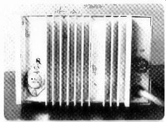
Fig. 6. Rear view of heat sink on prototype. A mica washer provides good
thermal contact between regulator and heat sink.
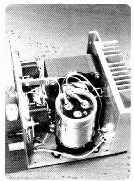
Fig. 5. Interior view of the author's prototype.
Heat sink must limit IC temperature to 75°C above ambient.
Construction. The 1.5-ampere bench supply was constructed in an aluminum enclosure measuring 4"H by 6'W by 5"D (10.2 x 15.2 x 12.7 cm). The back of the case was removed and replaced with an aluminum heat sink containing thirteen 1-inch (2.5-cm) fins. An interior view of the author's prototype is shown in Fig. 5.
The heat sink selected must be of sufficient size to limit the regulator temperature to no more than approximately 75°C above ambient when dissipating a maximum of 25 watts.
A mica washer will provide good thermal conductivity between the case of the LM317 regulator and the heat sink while maintaining electrical isolation. Be sure to apply a layer of silicone thermal compound on each side of the mica washer.
Also bolted to the heat sink of the author's prototype is the bridge rectifier, RECT1. The rectifier, however, is mounted on the inside of the modular heat sink and is not visible in the rear view of Fig. 6.
After drilling holes for the various components, and cutting the front panel for the meters, the cabinet was painted and labeled with dry-transfer lettering.
Next, using suitable hardware, all components except the filter capacitor and the meters were mounted. This provided enough room to wire the switches, potentiometers, etc.
To re-label the meter faces, first remove the meter covers. Then use a pencil eraser to carefully remove the existing numbers and a dry-transfer lettering kit to re-label the meter faces.
Although the wiring of the supply is simple and straightforward, several precautions should be taken to ensure the best possible load regulation. One lead of R1 should be connected directly to the case of the TO-3 package, the output terminal of the regulator IC. A separate heavy wire is connected from the case of the regulator directly to the positive output jack. Finally, the wiper of the VOLTAGE ADJUST control and the potentiometer lug connected to it should be wired directly to the negative output jack. This improves load regulation by providing remote ground sensing directly at the output of the supply.
In Conclusion. The finished supply will prove to be a worthwhile investment for any home lab. Although the goal of simplicity guided the design of this power supply (less than 25 components were used), its performance is more than adequate for most bench work.
With the VOLTAGE ADJUST control set for 15 volts, a 1-ampere load current will typically result in less than a 15-mV drop at the output and less than 1 mV peak-to-peak of ripple. Varying the ac from 90 to 125 volts causes less than a 10-mV output change. Output voltage drifts of 0.0190°C can be obtained if stable components are used for R1 and R2.
With a few additional parts, the output can be made to go down to zero.
This is accomplished by connecting the wiper (and the lug connected to it) of the VOLTAGE ADJUST potentiometer to a stable--1.25-volt reference. Output current can be increased by replacing the LM317 with either an LM350 (3 amperes) or an LM338 (5 amperes). If this is done, the power transformer and rectifier must be replaced with components that have increased current-handling capabilities. If a bipolar dc power supply is needed, you can build two supplies and connect the positive output post of one to the negative output post of the other. Alternatively, you can build a modified version of this project incorporating both an LM317 and a negative-voltage LM337.
Source: (Popular Electronics Electronic Experimenter's Handbook (1982)
Also see: Build an In-circuit Transistor Tester for $15