Indicates transistor quality and type without unsoldering from a circuit.
By Jules Gilder
LOCATING a bad transistor on a circuit board crowded with components all soldered in place can be a vexing problem. With an in-circuit transistor tester, however, you can determine the component's general quality and also avoid damaging components and/or the foil pattern due to excessive soldering-iron heat.
The simple, low-cost (under $10) tester described here will indicate when a suspect transistor is good or bad and, as a bonus, tell you the component's type (pnp or npn). Indication is through a pair of flashing LEDs. One LED flashes if the device is a good pnp transistor, while the other LED flashes if the device is a good npn type. If it is not good, either both LEDs will flash or neither will flash, depending on the type of transistor failure.
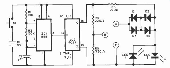
Circuit Operation. The circuit, shown in Fig. 1, is based on a 555 (ICI) timer operating as a 12-Hz multivibrator.
The output at pin 3 drives one flip-flop of IC2. This flip-flop divides the input frequency by two, but more important, delivers complementary voltage outputs at pins 15 (Q) and 14 (not-Q). These complementary outputs are connected to indicators LEDI and LED2 via current-limiting resistor R3. The LED's are arranged so that when the polarity across the circuit is one way, only one LED will glow, and when the polarity reverses, the other LED glows. Thus, with no transistor being tested, the LED's flash alternately.
The IC2 complementary outputs are also connected to resistor network R4 and R5, with the junction of these two resistors connected to the base of the transistor under test.
With a good transistor connected to the B, C and E terminations, when the correct voltage is applied to the three connectors, the transistor will turn on.
This produces a short circuit across the LED pair. For example, when a pnp transistor is under test, during the interval when the Q output is low and the not-Q output is high, the pnp device will turn on. In this mode, LEDI is shorted, LED2 is reverse biased and, for that half cycle, neither LED will glow. On the next half cycle, the conditions of Q and not-Q are reversed with Q high and not-Q low. Under these conditions, LED1 is off because it is reverse biased, and since the pnp transistor is cut off, it does not prevent LED2 from glowing. Thus, when testing a good pnp device, LED2 will flash, and when testing a good npn type, LED1 will flash.
If the transistor under test is open, both LEDs will flash. If the transistor has an internal collector-to-emitter short, neither LED will flash.
To compensate for low-valued resistors that may be present in the circuit being tested, R4 was selected to supply a large amount of base current to the transistor under test. This makes it possible to overcome in-circuit resistances across the collector-base or base-emitter junctions of as little as 40 ohms.
Diodes D1 through D4 become important if the transistor being tested has an internal short between its collector-base or base-emitter junctions. In such a case, half of the transistor acts like a diode and would normally conduct and indicate a good transistor. To overcome the possibility of this type of problem's occurring, diodes D1 through D4 are added in series with the collector.

Fig. 1.
PARTS LIST:
B1-9-volt battery with holder
C1-1uF, 16-volt electrolytic
D1 through D4-1N4148 or similar
IC1-555 timer
IC2-4027 dual flip-flop
LED1, LED2--Light emitting diode
R1-10.(X)0-ohms, 1/2-watt, 10% resistor
R2--50.000-ohms. 1/2-watt, 10% resistor
R3 -270 -ohms. 1/2-watt, 10% resistor
R4-220 ohms, 1/2-watt, 10% resistor
R5 -330 -ohms, 1/2-watt. 10% resistor
S1-Normally open spst pushbutton switch
Misc.-Suitable enclosure, mounting hardware, et al.
Note: The following is available from Redlig Systems Inc., 2068 79 St., Brooklyn, NY 11214: kit of parts (no battery or case) for $15, including post.


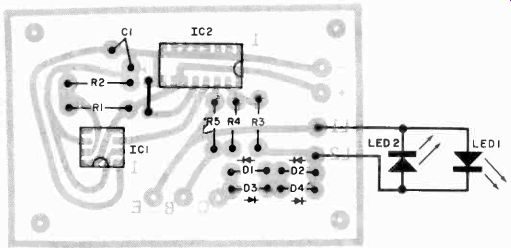
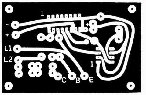
Fig. 2. Component placement guide (above) and actual -size foil pattern
(at right).
When D2 and D2 or D3 and D4 are conducting, they create a voltage drop of about 1.2 volts across the operating pair. This voltage adds to the drop across the transistor being tested, and if the transistor is good, the drop across it will be about 0.1 -volt, and the total drop across the LED's will be 1.3 volt for the half cycle that the transistor is turned on.
This is not enough voltage to turn on the appropriate LED. If, on the other hand, the transistor has a base -emitter or base -collector short, the 1.2 volts of diode drop is added to another 0.6 -volt drop to produce a total drop of 1.8 volts -- enough to turn on the LED. Therefore, internal shorts will cause both LED's to flash alternately.
Construction. The circuit is not critical with regard to parts placement and can be built up on a small piece of perforated board or the pc board whose foil pattern is shown in Fig. 2. Sockets for the ICs are optional, and be sure to observe the polarity of D1 through D4 and C1. The three leads to be connected to the transistor under test can be terminated at a transistor socket, or used as three color-coded leads terminated with small alligator clips or some form of needle tip to make in -circuit transistor pad connections.
The completed pc board can be mounted within a small enclosure that will also support the battery (and holder) and on/off switch S1. The two LEDs can be mounted on the cover using rubber grommets. To check the tester, depress S1 and note that the two LEDs alternately flash. If they flash together, one of them is improperly connected.
Source: (Popular Electronics Electronic Experimenter's Handbook (1982)
Also see: Precision References for Current & Voltage