BY BRIAN DANCE
Inexpensive detector converts ultrasonic sounds from insects, compressed gas leaks, etc., to an audio output.

EXPLORING the world of ultrasonic sound-which lies above approximately 20 kHz-can be exciting and educational. Here is a frequency spectrum beyond human hearing where many insects and rodents communicate with each other, where sounds from leaks in pressurized gas lines occur, etc.
The inexpensive circuits presented here convert these ultrasonic sounds to audio frequencies, enabling anyone to hear them. Also included is a simple ultrasonic transmitter circuit that will enhance your ability to probe this interesting electronics area.
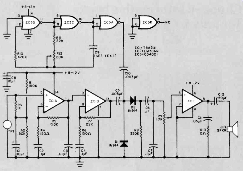
An Ultrasonic Receiver. The schematic diagram of a heterodyne-type ultrasonic receiver is shown in Fig. 1. This receiver heterodynes ultrasonic signals with those from an internal oscillator, converting them to audible frequencies for reproduction by a dynamic speaker. Thus, it allows you to "hear" any signals it detects.
Piezoelectric transducer TR1 converts ultrasonic waves impinging upon it into ac waveforms which are applied to the noninverting input of operational amplifier ICIA. Because a single-ended power supply is used, resistors R1 and R2 bias the noninverting input to one-half the supply voltage. Resistor R3, effectively connected across TR1 by electrolytic capacitor C1, damps the transducer's resonant response and broadens its bandwidth. At dc, R5 provides 100°° negative feedback to stabilize the operating point. At signal frequencies of interest, the gain of IC1A is 60 dB for the values given in Fig. 1.
The output of IC1A is directly coupled to op amp IC1B, a similar amplifier stage. The voltage gain of IC1B, about 43.5 dB with the component values specified, is somewhat lower than that of the preceding stage. Signals at the output of IC1B are capacitively coupled by C5 to diodes D1 and Q2.
===========

Fig. 1. In ultrasonic receiver, where incoming signals heterodyne with
those from the local oscillator to produce an audible output.
PARTS LIST FOR FIG. 1
C1, C8--10-µF, 25-V tantalum
C2, C4, C6, C7--0.1-µF disc ceramic
C3--0.01-µF disc ceramic
C5--0.005-µF disc ceramic
C9--180-pF (or 330-pF) disc ceramic, polystyrene, glass or silver-mica (see text)
C10--0.003-µF disc ceramic
C11--0.05-µF disc ceramic
C12--50-µF, 25-V electrolytic
D1, D2--1N914 signal diode
IC1--TBA23I dual op amp (see note)
IC2--L.M386 audio amplifier
IC3--CD4001 quad 2-input NOR gate
The following fixed resistors are 1/4-W, 107: carbon composition:
R1, R2, R5--150,000 ohms
R3--1000 ohms
R4 ,R6--150 ohms
R7, R11--22,000 ohms
R8--330,000 ohms
R10--470,000 ohms
R13.-10 ohms
R9--10,000-ohm linear-taper potentiometer
R12--20,000-ohm linear-taper potentiometer
SPKR--8-ohm dynamic speaker
TR1--Piezoelectric ultrasonic transducer
Misc.--Printed circuit or perforated board: suitable enclosure: Hook-up wire; dc power source; machine hardware; etc.
Note--The TBA231 dual op amp is imported from the U.K. by: SG –ATES Semiconductor Corp., 435 Newtonville, MA 02160 (Tel: 617-969-1610).
===========
Also applied to the diodes is the output of an ultrasonic oscillator comprising IC3 and its related components. The frequency of this oscillator is determined by the setting of potentiometer R12 and the capacitance of C9, which is chosen so that the oscillator output corresponds to the resonant frequency of the transducer. (Transducers are readily available from surplus dealers with resonant frequencies ranging from 22 to 44 kHz.) The two diodes form a nonlinear net--work. Hence, when signals from the oscillator and the op amp are applied, they heterodyne with each other. If IC3 oscillates at a frequency fairly close to that of an ultrasonic wave detected by TR1, an audible beat signal will appear at the cathode of D2 at a frequency equal to the difference between the two ultrasonic frequencies. The process is similar to that performed in a conventional superheterodyne r-f receiver. The beat note, which can be tuned by adjusting R12, is amplified by IC2, an audio IC, to a level sufficient to drive the dynamic speaker.
Potentiometer R9 serves as an audio gain control.
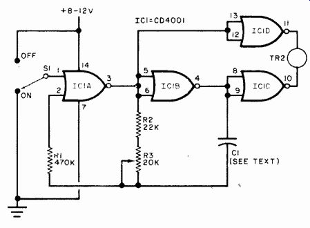
An Ultrasonic Transmitter will help you explore the ultrasonic region more fully. A suitable design is shown schematically in Fig. 2. The circuit is similar to the local oscillator stage in the receiver, but the previously unused fourth gate in the 4001 is employed to provide push-pull drive for transducer TR2. The output frequency is variable by means of R3. The capacitance of C1 should be chosen so that the nominal oscillating frequency corresponds to the resonance of the transducer. As was the case with C9 in the receiver, C1 should be 180 pF if 44-kHz transducers are used, or it should be 330 pF for use with 22-kHz transducers.
Construction. Either printed circuit or perforated board can be used to duplicate the transmitter and receiver circuits. Parts placement is not especially critical. The use of sockets or Molex Soldercons is recommended when mounting the IC's on the boards. Be sure to observe normal precautions when handling the CMOS devices. Install polarized capacitors and semiconductors with due regard for polarity and pin basing. Batteries are well suited to power the transmitter and receiver circuits.
Note that, when transmitter switch S1 is in the OFF position, the output states of IC1's gates are frozen. The quiescent current drain of the circuit is so small that no power switch is necessary. If a battery supply is used with the receiver, however, an spst power switch should be used to disconnect the circuit from the supply when it is not being operated.
Use. Receiver potentiometer R12 tunes the circuit across a limited portion of the ultrasonic frequency range. Apply power and. adjust audio gain control R9 until some noise is heard through the speaker. Then rub the palms of your hands in front of TR1. The receiver will detect the ultrasonic energy from the rubbing.
You will notice that TR1 has a very directional response. This is due to the fact that ultrasonics have very short wavelengths (compared to those at audio frequencies) and are thus subject to less diffraction at the edges of large objects. Also, ultrasonic waves behave like light waves in that they tend to travel in straight lines.
It's interesting to note that if coupling capacitor C10 in the receiver is disconnected from the diode mixer, the receiver will still detect ultrasonic signals if more than one frequency is present. The frequencies present at the input will beat against each other to produce an audible output. This can be verified by repeating the palm-rubbing experiment described earlier after the coupling capacitor has been disconnected. The speaker will still generate an audio output even though no local oscillator signal is being injected into the diode mixer.
If an ultrasonic wave generated by transmitter transducer TR2 now impinges upon TR1, the random noise reproduced by the speaker will drop to a low level. No tone will be heard because only one frequency is applied to the mixer. Stray coupling that allows a portion of the local oscillator output to reach the mixer will create an audible beat.
When the receiver and transmitter are operating in the same room, a signal will be heard as R12 tunes the receiver across its range. The two transducers do not have to be directly facing each other if enough hard surfaces in the room reflect the ultrasonic waves, and the room is not so large that it introduces excessive signal attenuation.
The circuits presented have been successfully used with ultrasonic transducers from many different sources, including those used in television receiver remote control accessories. Of course, if you want to tune in several ultrasonic "bands," you can use a multiple-pole rotary switch to select the appropriate transducer and its corresponding oscillator capacitance. Experimentation indicates that the receiver can "hear" the transmitter at distances up to 125 feet if the transducers are aimed at each other, The use of a suitable parabolic reflector in tandem with TR1 and/or multiple driven transmitter transducers should result in even greater useful range.
Other Suggestions. We have already mentioned the possibility of using these circuits for signaling purposes.
Many other practical applications exist.
For example, leaks in the rubber sealing of car doors and windows or in the sealing of a freezer door. The transmitter is placed in the car or freezer and fills the interior with ultrasonic waves. The walls of the interior reflect the waves to create a wide dispersion of ultrasonic energy. If the receiver's transducer is moved over the exterior, a tone will be heard whenever it passes any leaks.

Fig. 2. This ultrasonic transmitter employs four NOR gates.
PARTS LIST FOR FIG. 2
C1-180-pF (or 330-pF) disc ceramic, polystyrene, glass or silver mica capacitor
IC1--CD4001 quad dual-input NOR gate
R1--470,000-ohm 10%, 1/4-W resistor
R2--22,000-ohm 10%, 1/4-W resistor
R3--20,000-ohm linear-taper potentiometer
S1--Spdt switch
TR2-Piezoelectric ultrasonic transducer
Misc.--Printed circuit or perforated board; suitable enclosure; hook-up wire; dc power source; machine hardware, etc.
Source: (Popular Electronics Electronic Experimenter's Handbook (1982)
Also see: Open-Door "Fridge Alarm" Stops Food Spoilage And Energy Waste