By John McVeigh
"A craftsman is only as good as the tools with which he works" is as true in the field of hobby electronics as any other.
Tools are no substitute for knowledge, of course, but lacking key items or using improper ones can put severe limitations on an experimenter's activities.
The type and variety of tools and test equipment that an electronics hobbyist possesses have a direct bearing on which areas of personal electronics he will be able to explore.
In this editorial focus, we discuss how an electronics workbench should be set up and consider several factors that should be taken into account in deciding what items you need for your workbench as related to your electronics interest.
The Work Area
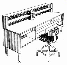
The workbench is the one place above all others where the electronics
buff pursues his hobby. It is there that he takes a circuit idea or description
and reduces it to a working model. Since a serious hobbyist spends a
substantial amount of his special-interest time at his workbench, it
should be designed for maximum user comfort and safety, and minimum fatigue.
If space availability and resources permit, the electronics workbench
should be just that and only that, because many projects require more than
just a day's work. Thus, a partially assembled (or repaired) project can
be left undisturbed until the next time it is to be worked on.
In contrast, a work area that serves double duty, as, say, a kitchen table, would cause gross inefficiency and frustrations. In this case, everything would have to be periodically removed so that the "work area" could be used for its original purpose.
The fundamental requirement for an electronics workbench is that it provide a solid, flat, rugged, nonmetallic surface on which one can work. Of course, an actual workbench-a structure specifically designed and constructed for this purpose-can be used. However, if budgetary constraints rule this out, a sheet of 1/2 or 3/4-inch plywood and a pair of wood saw horses can form the nucleus of a fine workbench.
In any event, the work area should be at least 24 inches (61 cm) deep and 48 inches (122 cm) wide. Having a work area of that size or larger will allow you to spread out components, a schematic drawing or assembly manual, a chassis, and tools, and still have some elbow room! A smaller work area will likely lead to crowding, fatigue, impatience and wiring errors.
A highly desirable feature is having one or more shelves above the main work area. Such shelves allow one to mount frequently used test equipment (a multimeter, oscilloscope, power supply, etc.) within easy reach without permanently tying up substantial portions of limited work space.
The work area surface should be covered with a ribbed rubber runner. This runner will absorb punishment that would otherwise damage an unprotected work surface. Also, its ribbed surface will prevent hand tools, hardware, and small components from rolling off the work bench and onto the floor.
Selecting a chair will largely be influenced by the physical characteristics of the workbench. The chair should be high enough to put one's elbows at the same level as the work area. If the workbench is much higher than the aver age kitchen table, use of a common kitchen-type chair would be inadvisable.
The ultimate in work chairs is a drafting chair with adjustable seat height and back support.
Lighting and Power. The area in which the workbench is installed should be well illuminated. If possible, the work bench should be directly below a ceiling light fixture. Light from this fixture can be supplemented with that from a lamp on the workbench. A compact high-intensity type will provide good spot illumination, but many experimenters prefer to use a drafting lamp with an articulated support arm, such as the Luxo Model LS-1 /A. This lamp can accommodate a 100-watt incandescent bulb, has a 45-inch adjustable arm, and includes a clamp so that it can be mounted on the edge of the workbench. For work on densely packed circuit boards and compact projects, a similar lamp with an illuminated magnifier is an invaluable aid.
If the need for an illuminated magnifier arises only occasionally, a less costly, hand-held unit such as the GC Electronics Model 22-282 is a good choice.
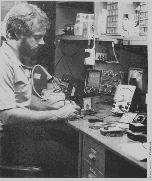
-------A well-planned electronics work area includes room for the project,
test equipment, and storage.
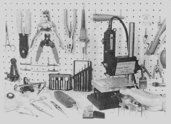
-------Use of pegboard and hooks permits convenient storage of tools.
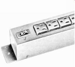
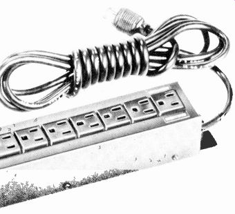
--------Heath Model HD1274 power distribution strip.
There should be a source of ac electrical power near the workbench. The bench should therefore be positioned near at least two electrical wall outlets, and a bench-mounted power distribution strip with a minimum of six sockets should be plugged into one of them. The strip will be used to channel power to test equipment, lamps, soldering tool, etc. Choose a strip with a minimum cur rent rating of 15 or 20 amperes and three-conductor sockets. One with a master on/off switch or individual switches for each outlet is convenient to use. Some include a master fuse or circuit breaker, or even individual ones for each outlet to back up the line's master fuse or circuit breaker.
Storage. A key to high workbench utility is organization. Tools, hardware, electrical components and similar items should be stored in a logical manner that ensures quick accessibility. Certain tools, for example, can either be kept in nearby drawers or hung on a piece of pegboard mounted on a nearby wall.
The best way to store hardware and small electrical components is in suit ably sized storage bins. There are modular ones with drawers that are made of transparent styrene to allow quick visual inspection of their contents.
Hobbyists with many items to store can buy several such small storage cabinets. Some manufacturers models with different characteristic drawer sizes to hold certain items. Modular storage cabinets can be stacked either vertically or horizontally on shelving above the main work area.
After a few years, most electronics hobbyists build up a respectable "junk box" of discarded chassis, old projects, etc., which are kept around for parts scavenging purposes. Such items are usually much too large to fit in modular storage cabinets. A nearby closet that is not being put to another use is ideal for junk-box storage. If one is not available, a wooden toy chest or a free-standing metal cabinet will probably do.
Tools for Electrical Work
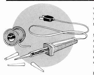
Much electronic-building and service work is centered around the process of making secure connections between conductors by soldering. That is the process by which two or more pieces of metal are bound together by a metal alloy that's applied to the connection in a molten state. This section will deal with implements needed to do this work, as well as other facets that relate to electrical assembly.
Soldering Irons. A soldering tool should supply sufficient heat to melt solder by heat transfer when the iron tip is applied to a connection to be soldered. There are two general classes of soldering irons-guns and pencils.
A typical soldering gun is larger, heavier and generates more heat than the average pencil. Soldering of heavy duty conductors or connectors calls for use of a gun because it can generate enough heat to quickly bring a heavy metal joint up to the proper soldering temperature.
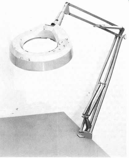
--------Luxo Model LFM-1/A illuminated magnifier.
Soldering irons in this category are called guns simply because they resemble pistols, as shown in an accompanying photo. The gun's "trigger" is actually a switch that controls application of ac power to a built-in transformer and thence to the heating element. The working temperature is reached almost immediately. Some models feature multi-position trigger switches to provide different heat levels. For example, a two-detent switch might give the user a choice of generating 100 watts or 150 watts, depending on whether the trigger is fully or partially depressed.
At the other end of the spectrum are small, lightweight soldering pencils.
They can generate as little as 12 watts of heat, or as much as 50 watts, depending on the particular model. A relatively low-power pencil such as a 25-watt unit is well suited for light-duty work such as soldering on printed-circuit boards. Some medium-duty applications like chassis wiring require a higher-wattage heating element. Many pencils, called modular soldering irons, use interchangeable heating elements and tips which mate to a main pencil body. Such elements screw into a threaded receptacle at the end of the pencil.
------Wahl Model 7295 safety stand holds iron and cleans tip.
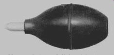
------Ungar Solder-Off desoldering bulb.
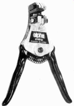
------Alpha STRP-25 plastic-blade wire strippers
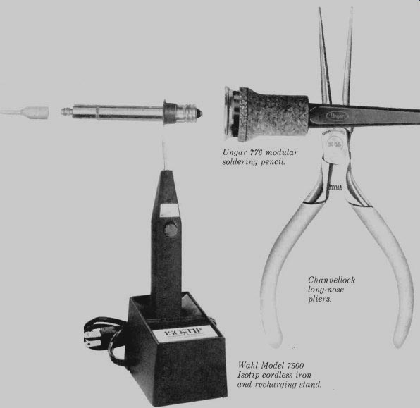
------Ungar 776 modular soldering pencil.
------Channellock long-nose pliers.
-------Wahl Model 7500 Isotip cordless iron and recharging stand.
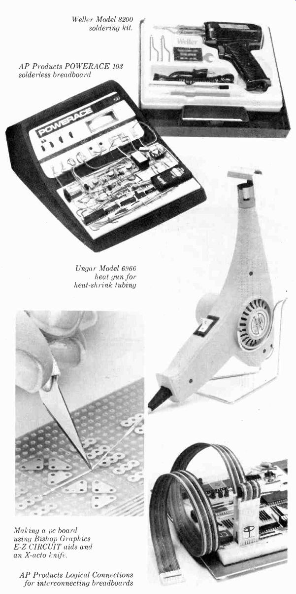
------Weller Model 8200 soldering kit.
------AP Products POWERACE 103 solderless breadboard
-------Ungar Model 6966 heat gun for heat-shrink tubing
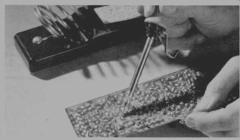
--------Making a pc board using Bishop Graphics E-Z CIRCUIT aids and an X-acto knife.
---------AP Products Logical Connections for interconnecting breadboards
Some heating elements have ceramic bodies with tips of various shapes permanently bonded to them. Others are ceramic or stainless steel units that are terminated with threaded studs on which any one of several different-shaped tips can be mounted. The advantage of such a modular soldering pencil is that it can be assembled in any of several permutations that is optimized for a specific soldering job.
There are tips available for modular soldering pencils to handle most soldering tasks. Very fine, almost needle-like tips are used on printed-circuit boards with IC and component foil pads that are very closely spaced. Larger, blunt chisel and pyramid tips can store and transfer greater amounts of heat for more massive, widely spaced connections. Bent-chisel types can get into difficult-to-reach areas. Whatever size and shape tips are chosen, it's best to buy plated (as opposed to raw copper) tips. Plated tips cost more, but they last up to ten times longer than raw copper tips. The principal advantages of raw copper tips are low cost and more efficient heat transfer. Plated tips, however, transfer heat with enough efficiency for almost any soldering job. Note that before any tip is mounted, its threads and those of the heating element stud should be treated with an antiseize compound to facilitate tip removal.
Power is usually applied to a soldering gun on an intermittent basis. The tip of the gun will heat up to working temperature very quickly, and it will cool off soon after power is removed. There fore, the gun can be left lying on its side on the workbench, picked up and powered to make the required connection, and then laid on its side again. A typical pencil, however, takes a few minutes to attain working temperature. This means that during a typical work session the pencil will be continuously powered and its tip will remain hot for the entire inter val. Therefore, some method must be employed to keep the iron secured in a safe place at working temperature.
One solution to this problem is a special soldering iron holder. This may be a coiled steel form into which the hot soldering iron can be inserted. Most stands of this type also include a sponge which can be kept moistened and used periodically to clean the soldering tip. A more deluxe solution incorporates the foregoing with an iron and a control console that offers switch-selectable temperatures, usually low, medium, and high. This system is called a soldering station. Obviously, this is more convenient than waiting for a modular pencil's heating element to cool, unscrewing it from the holder, and then replacing it with another heater/ tip combination. Predictably, however, soldering stations are expensive compared to basic soldering pencils.
Among the manufacturers that produce soldering stations are Weller, Ungar, and Heath.
Special Considerations. The proliferation of metal-oxide semiconductor de vices has focused the attention of some manufacturers upon characteristics of certain soldering irons that were largely ignored until recently. As you may know, MOS devices have gate structures that are extremely susceptible to damage by electric potential gradients such as those which can be generated by friction (i.e., static electricity). A source of such electric fields can be the soldering equipment itself.
There are two sources of trouble some potential differences associated with soldering irons. The first is common to most soldering irons-electro static tip potential. Static electricity can be set up in an ordinary soldering tip and can be transferred to the component to be soldered when the tip is placed next to one of its leads. If the electrostatic potential is high enough and the MOS device is unprotected, its delicate gate structure will be destroyed. The solution to this problem is to place the tip at ground potential so that static charges do not have a chance to accumulate. Several manufacturers now produce special soldering irons whose heater/tip assemblies are grounded. These units are readily identifiable by their three-conductor NEMA plugs for insertion into three-conductor power sockets.
Another source of potential trouble is peculiar to a certain type of soldering iron. Some of the more sophisticated soldering implements (most of them soldering stations) feature automatically controlled tip temperature. These implements employ some type of heat sensing and closed-loop feedback control to gate power to the heating element. This allows the control circuit to compensate for variations in the amount of heat being drawn from the soldering tip and keep the tip at a constant temperature. The switching action of some controlled-output soldering implements can generate voltage spikes" which can be transmitted to /and adversely affect a MOS device. Sing.
manufacturers, such as Ungar, have designed their controlled-temperature soldering stations and irons in such a way that voltage spikes are kept to a low value.
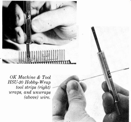
---------OK Machine & Tool HSU-30 Hobby-Wrap tool strips (right) wraps,
and unwraps (above) wire.
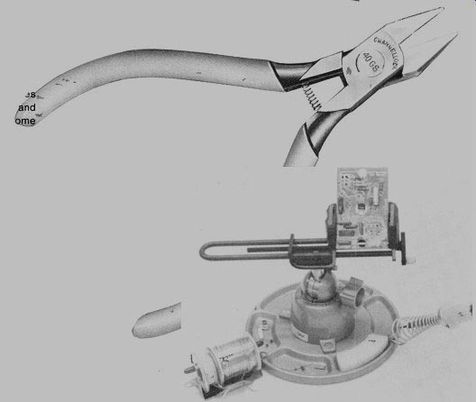
---------Channellock 40GS Little Champ diagonal cutters.
---------Panavise circuit-board work station.
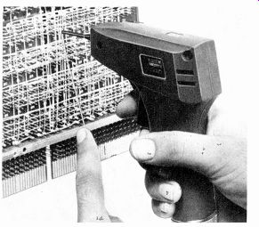
--------OK Machine & Tool BW-2630 motorized wrapping tool.
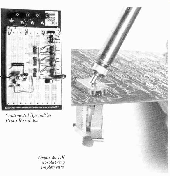
-------Continental Specialties Proto Board 108.
-------Ungar 50 DK desoldering implements.
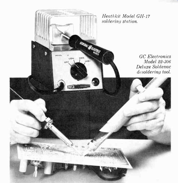
--------Heathkit Model GH-17 soldering station.
-------GC Electronics Model 22-306 Deluxe Soldavac desoldering tool.
Cordless Irons. All of the soldering irons discussed so far rely on ac power cords. However, there are times when it is inconvenient to be tied to a 117-volt line. Here, a cordless, battery-operated soldering iron serves well. These compact, hand-held tools employ recharge able NiCd batteries as a power source.
Recharging is done automatically when the iron is placed in its recharger/stand (assuming the charger is plugged into an ac outlet, of course).
In operation, the tips come up to working temperature in five to eight seconds and cool off to ambient temperature in one minute or so. They can be used to make the same kinds of solder connections that pencils do.
The number of solder connections able to be made before recharging is required varies according to a particular model. Typically, about 125 or so soldering connections can be made on one charge. For a standard iron, a typical charging interval of approximately 14 hours is needed to return the cells to full strength. There are quick-charge irons, however, that require only one hour. Others take three or four hours.
Many optional tips for battery-powered irons, all differing in shape and size, can be snapped into the bodies. A light is often built into the case of the iron to illuminate the work area whenever battery power is applied to the heating element.
It is obvious that there are many different types of soldering irons avail able. Some are better suited for a particular kind of soldering job than are others. An experimenter who works only with printed circuit boards will find that a soldering pencil (especially a modular one) will be adequate for most (if not all) of the soldering connections he has to make. Someone who builds projects employing coaxial connectors and heavy-gauge wiring will need a higher-power soldering gun. Another person will find a cordless soldering iron an invaluable implement for work far from ac outlets. The choice is often easy for hobbyists with broad electronics interests. They own one of each. In fact, many hobbyists have more than one modular pencil body so that much tip switching is avoided.
Solder. No solder connection can be made without solder. The most common type of solder used in electronic work is an alloy consisting of 60% tin and 40% lead. This alloy is drawn into a hollow wire whose center is filled with an organic paste-like material called rosin.
The resulting product is known as "60/ 40 rosin-core solder." It is completely molten when healed to approximately 375°F (190°C) and solidifies as it cools. If conditions are right, it will form a rigid, conductive bond with the metals to which it has been applied.
There are other solder alloys containing different proportions of tin and lead that are sometimes used in electronics work. The eutectic alloy of tin and lead, that mixture having the lowest melting point, is 63/37. It melts at 361° F (183° C) and is used in applications where applied heat must be kept to as low a level as possible. An equal mix ture of tin and lead, called 50 / 50 solder, is completely molten at 415°F (213° C), while a 40 / 60 tin/lead alloy has melted completely by the time it attains a temperature of 455° F (235° C). The latter two alloys are not used very often in electronics work today because their higher melting temperatures require more heating of the solder joint, which might damage heat-sensitive semiconductors.
For almost all electronics work, 60/ 40 rosin-core solder should be used. This alloy is available in wire form in several gauges. Thinner gauges are to be preferred over thicker ones. For general-purpose soldering, 18-gauge wire solder is a good choice. Close printed-circuit work calls for the use of No. 20 or 22 solder. Finely drawn solder is not only easier to position above a connection on a densely packed board, but also requires less heat for the formation of a given joint. This is true because fine solder sinks away less heat into the roll of solder than do thicker gauges.
To allow solder to form a good joint, rosin flux must be applied to the connection. The flux is available separately, as well as imbedded in wire solder.
Even with the latter, it's a good idea to have extra flux on hand so that some can be added to a stubborn joint that won't readily accept solder. Flux is needed to scrub away the microscopic film of oxides on the surfaces of metals to be soldered, and it forms a protective film that prevents re-oxidation while the connection is heated to the point at which the solder melts.
For applications other than electrical wiring, solders with acid fluxes are available. However, the acid is highly corrosive and will damage both electrical components and wiring. Accordingly, it should never be used in electronics applications.
Other Soldering Tools. Very useful in soldering work is a small hand tool called the soldering aid. It consists of a plastic or wood wand with a pointed metal tip at one end and a notched metal tip at the other. The blunt end of the aid is used to clear solder from holes in pc boards and from solder lugs. The notched end can be used to make right-angle bends in components leads, to hold leads and wires while the solder joint is made, and to pry leads away from pc boards and lugs during desoldering operations. There are several other soldering aids available, each with different types of tips (metal brushes, reamers, scrapers, etc.) suited for a specific task.
To protect heat-sensitive components during soldering, heat sinks are required to divert potentially damaging heat from delicate components. A set of alligator clips or commercial clip-on heat sinks made for this purpose can be used. They are clipped onto component leads while the soldering job is accomplished.
Those who work with printed circuit or perforated boards will find a so called "third hand" circuit-board holder a valuable aid. This type of device usually includes a pivoting head that can rotate to just about any desired angle to facilitate soldering.
Desoldering Equipment. On those occasions when a component must be replaced or a circuit rewired, desoldering must be performed. There is a whole series of desoldering implements and aids available to today's electronics hobbyist. Most rely on either vacuum or capillary action to remove the solder after it has completely melted.
A common desoldering tool that employs the vacuum principle is a rubber suction bulb with a Teflon tip. The bulb is employed in the following manner: A soldering iron is applied to the connection to be undone until the solder has melted completely. Then the bulb is squeezed and its tip butted up against the solder joint. The bulb is allowed to expand quickly, creating a mild vacuum which draws the molten solder up into the bulb. Another vacuum type uses a spring-loaded plunger.
The other method of removing solder is to employ capillary action. If a copper braid is placed over the solder to be removed and a soldering iron placed over it, the solder will melt and be drawn up by the wicking action of the copper braid. Specially constructed braids are available for this purpose.
Removing multi-lead components such as ICs presents a special problem. If the component to be removed is still functional, it must be unsoldered quickly lest it be damaged by heat.
Alternatively, if the device is defective, it must be removed fairly quickly or else printed-circuit foil conductors might be lifted from the board by excessive heat.
The solution to this problem is to employ specialized devices. These might be a special DIP-shaped soldering iron tip and a spring-loaded IC extractor tool. The tool is placed above the IC to be removed and locked into position. The special tip is then mounted on the heating element of a modular iron. When the tip is hot, it's applied to all the dual-inline IC's pins on the foil side of the board. The extractor tool lifts the IC off the board as soon as the solder holding it melts. There are desoldering tools available for use with other IC and transistor cases.
The final item we will mention with respect to solder is flux remover.
Although rosin flux is not very corrosive and can usually be left on a circuit board with no ill effects, there are some purists who insist on removing all of it.
The circuit board can be scrubbed with a toothbrush and an organic solvent like Toluene to remove flux, or it can be sprayed with a product such as GC Electronics No. 22-270 Flux Remover & Cleaner Spray.
Printed-Circuit Aids. For those who intend to make their own printed-circuit boards, special items are needed for layout and fabrication. If pc foil patterns are to be taken from the page of a magazine, a kit like GC Electronics' Lift It (No. 22-326 or 22-318) is ideal.
Those who are designing complex boards from scratch might choose to employ Bishop Graphics or similar pc materials and photosensitizing compounds to produce sharp, detailed foil patterns. A glass or plastic pan, etchant solution, rubber gloves, blank boards, a heat lamp, a thermometer, and a small drill will also be needed.
Complex circuit boards are best produced by means of photographic techniques employing master artwork or the copying of etching and drilling guides published in magazines. Simple boards, however, can be fabricated by the direct application of etchant-resist ink by means of a felt-tip pen made especially for this purpose. Whichever means is employed to produce a printed-circuit board, it should be pre pared to accept solder well. One item that's well suited for this application is a nonmetallic scrubbing pad such as the Scotchbrite pad. It can be used to remove etchant resist from the board prior to drilling as well as to remove oxidation from foil.
Wrapping Wire Equipment. A fairly new method of making connections between points in a circuit is the wrapped-wire technique. This involves tightly wrapping the stripped ends of a wire around square (usually 0.025-by-0.025-inch or 0.6-by-0.6-mm) terminal posts.
Wrapped-wire connections are quickly and inexpensively made, and are used most often in digital circuits assembled on perforated board.
There are many tools available to those who want to assemble projects using the wrapped-wire construction method. These include a manual, multi function tool that strips insulation from No. 30 wrapping wire, makes a modified wrapped-wire connection (which adds about 11/2 turns of insulated wire to enhance mechanical stability), and un wraps the wire when a connection is to be changed or removed.
Besides the manual wrapping-wire tools manufactured by OK Machine and Tool Corp., Vector Electronics Corp., and other companies, there are motorized tools available for wrapping-wire applications. One such motorized tool is the Model BW-2630 by OK Machine and Tool Corp. It's powered by two NiCd C cells (not included) and accepts one of two bits-one for No. 30 wire, the other for No. 28 or 26 wire.
Besides a wrapping tool, there are several other items the hobbyist interested in utilizing this construction technique must have. The most obvious additional one is wrapping wire. This special wire is available in a variety of colors and comes in spools or in packs of pre cut lengths with stripped ends. Also necessary are IC sockets designed for wrapped-wire applications and perforated circuit boards with holes of the proper spacing.
Solderless Breadboards. Ideal for de signing or experimenting with circuits is a solderless breadboard. This is a plastic block with arrays of holes spaced 0.1 inch (2.5 mm). The block is mounted on a supporting structure and has embedded in it a series of electrical conductors which interconnect adjacent rows or columns of holes. These boards readily accept IC pins and the leads of other electronic components, allowing the hobbyist to build up a circuit with secure, reliable connections without having to resort to soldering or wrapping wire.
A typical solderless breadboard is Continental Specialties' Proto Board No. 103. This board has binding posts for ground and three supply or signal voltages and offers enough tie points for a fairly complex circuit. AP Products, in turn, offers three sophisticated bread boards. These POWERACE models include power supplies and, depending on mod el, logic indicators, one-shots, pulse detection, two-phase clock, and data switches. Among other companies offering breadboard products are the OK Machine and Tool Corp. and the Heath Company. There are a large variety of finished breadboards available, ranging from simple units with perhaps two binding posts to complex models with built-in fixed or variable regulated supplies, signal generators, potentiometers, etc.
Solderless breadboards are valuable design and experimenting aids that greatly facilitate circuit prototyping. No well-appointed electronics workbench is complete without one!
Wire Cutters and Strippers. We now move into the area of hand tools designed for the manipulation of electrical wires. Before a wire can be soldered, wrapped, or a connector crimped onto it, it must be cut to length and its insulation removed.
The most popular implement used to cut electrical wires and the leads of electronic components is the diagonal-
cutting pliers, usually called diagonals or dykes. The diagonal cutters intended for electronics applications should be used only to cut soft metal conductors-never to cut iron or steel wire.
The size of the diagonals to be used is determined by the diameter of the wires to be cut. Cutters up to 5 inches long are often employed in electronics applications. Any cutters chosen should be made of high-quality tool steel so that they will make a sharp, clean cut.
The tips of the cutters should be tapered to allow the user to reach a particular wire in a crowded area. Cutter jaws should be very well aligned so that cut ting edges meet squarely and allow little or no light to pass through when held together. Cutter action should be smooth and clean.
There are, too, a wide variety of specialized cutters-tip cutters, end nippers, etc.-that are handy to have if the budget allows. Diagonal cutters can, if used with care, be employed to strip insulation from wires. Also suited for this purpose is the familiar, inexpensive, yellow-plastic-handled wire cutters / strip pers. The object of wire stripping is to remove insulation from the wire without nicking or cutting the conductor.
Far more convenient than traditional wire cutters/strippers are precision, automatic strippers. Although such tools are expensive, they can be real timesavers when there's a lot of point-to-point wiring to be done.
Sometimes a situation arises where insulation is to be added to a wire or wire splice. Although PVC (not cloth!) electrical tape can be used for this purpose, heat-shrink tubing is far more convenient. It is composed of a special plastic material which contracts when heated to a relatively high temperature.
Heat-shrink tubing comes in a variety of lengths and diameters to suit any number of applications. There is even heat-shrink electrical tape available for a really tight fit.
Pliers. One of the most commonly used class of tools is pliers. In electrical work, needle- and long-nose pliers are necessities. Mechanical work, on the other hand, often involves the use of slip-joint or gas pliers.
Frequent tasks for long-nose pliers include holding wires in place during soldering, acting as a heat sink to protect a delicate component, bending component leads to fit mounting holes on a circuit board, and pulling wires through a panel or chassis hole.
Such pliers are available in a wide range of sizes and configurations. A small size (about 4.5 inches) with a long, thin nose is best for electronics applications. A single pair of long-nose pliers is adequate for most jobs, but having several on hand can simplify a task.
Alignment Tools. If a hobbyist intends to work on communications projects, he should have a set of alignment tools on hand. Among the items in this category are a neutralization tool (a plastic or wooden tubular holder with a small metal blade inserted in one end), a nonmetallic screwdriver, and a plastic hexagonal slug-alignment tool. Most alignment tools are nonmetallic and fairly long in size. Using a nonmetallic tool enhances safety because of the tool's insulating property. It also prevents disturbance to sensitive r-f circuits that can be detuned merely by bringing a metal tool near frequency-determining devices. Similarly, the use of a long alignment tool minimizes the effects of hand capacitance.
---
Tools For Mechanical Work
Drivers. This category includes screw drivers and nut drivers. Both are extremely important to the mechanical work ancillary to personal electronics hobby activities.
There are two basic types of screw drivers-blade and Phillips. A typical electronics project will employ a dozen or more screws to fasten circuit boards, terminal strips, etc., to the chassis or enclosure. Therefore, a complement of screwdrivers must be kept on hand.
Blade screwdrivers come in a great number of sizes. A minimum of three should be at hand for electronics work, with the following blade sizes: 1/8 inch; 3/16 to 1/4 inch; and 5/16 inch or larger. If possible, a larger selection of blade screwdrivers should be maintained.
There are several "specialty" screw drivers which are not necessary, but are on occasion very handy. One is a "stub by" screwdriver with a short shaft. It's very useful in tight quarters. In really tight situations, an offset screwdriver can be especially helpful. Another useful "specialty" screwdriver is one that holds a screw against the blade of the driver. The Stanley Works makes such a device, called the "Screwstart", which can be added to an existing driver.
Phillips screws, those with star-shaped holes in their heads as opposed to straight slots, are often found in electronic equipment. Phillips screwdrivers, like many other hand tools, come in a variety of sizes. There are four standard points, No. 1 through 4. The star-shaped hole in a Phillips screw and the tip of a Phillips driver must fit together properly so that the walls of the screw head or the tip of the driver or both will not be damaged. In electronics work, No. 1 and No. 2 Phillips drivers are those usually employed.
One way to satisfy screwdriver requirements is to buy a driver set containing a handle into which any of several driver shafts can be inserted, such as Xcelite's Model CK-5 driver set. Each of the shafts is doubled-ended, yielding two different tips on each shaft.
Nutdrivers are like screwdrivers except that they fit nuts instead of screw heads. They are very useful in mounting a nut on a captive threaded stud and in holding a nut while its screw is being tightened. (A pair of pliers should not be used to hold hex- or square-head screws.) Nutdrivers are available as individual drivers with separate handles, as individual driver shafts that plug into a common handle, or as individual sockets that plug into a universal handle/shaft combination. There are master driver sets available that include nutdriver shafts, slotted screwdriver shafts, and Phillips screwdriver shafts.
Nutdrivers are available with either solid or hollow shafts. The major advantage to hollow-shaft drivers is that they allow the user to keep a grip on the nut even though the screw on which the nut is mounted is protruding. Stubby nutdrivers are handy when work is to be done in tight places. These can be bought in sets that include a large slip-on handle that multiplies torque. Extra-large nut drivers permit the installation of potentiometers and rotary switches without risking damage to the control panel.
Selecting Drivers. As in the case of pliers, cutters, and other hand tools, there are many, many companies manufacturing drivers. It is better and more economical in the long run to buy high-quality tools than so-called "bargains." How can the electronics hobbyist tell that the tools he is thinking of buying are of high quality? Here are a few things to look for.
The handles should be sturdy, made of heavy-duty plastic, and preferably have rubber grips for comfort. Tool shafts should be deeply and firmly embedded into handles in the case of individual drivers (as opposed to plug-in sets). The shafts of plug-ins should lock firmly into place when inserted in the master handle. Tools should have shafts of tempered, plated steel and have ground tips. They should be well-balanced and comfortable in the hand. Per haps the easiest way to choose high-quality tools is to stick with established names such as Xcelite, Stanley, Vaco, Channellock and Sears Craftsmen.
Allen Wrenches and Miniature Drivers. Many control knobs have small Allen or slotted setscrews. To install or remove such knobs, a set of Allen wrenches and miniature screwdrivers should be kept on hand. There are other uses for miniature tools, especially in such fields as remote control modeling, model railroading and slot-car racing, and the fabrication of miniaturized electronic projects. Performing such work when equipped with a precision miniature tool set is so much easier that the purchase of such a set is well justified.
One of the big names in miniature precision tools is Moody Tools, Inc. (4260 Crompton Avenue, East Greenwich, RI 02818). Jensen Tools & Alloys is another, with a host of precision tools, including many tool kits (1230 So. Priest Dr., Tempe, AZ 85281).
Wrenches. There are several types of wrenches that the electronics hobbyist will need from time to time. Among them are the open-end wrench, the box wrench, and the plier wrench or "vise-grips" tool.
Open-end wrenches are used primarily on the large hexagonal nuts that secure switches and controls to project panels (actually, a large nut driver is better suited for this application) and to operate chassis punches. The box wrench has similar applications but has the advantage of completely enclosing the nut, thus eliminating the danger of slippage that can mar a finished front panel. Box wrenches are not essential, but are handy to have around if the workbench budget permits.
The plier wrench or "vise-grips" is a tool that is not found on every electronics workbench, but it should be. Not only is this an excellent tool for applying brute torque to the task of turning bolts, nuts and shafts, it can also serve as a restraining tool and as a "third hand" for holding small parts, circuit board assemblies, etc. A pair of vise-grips can be adjusted for a given jaw opening and has a locking lever and in some cases a separate unlocking lever for quick-action clamping and release. Vise-grips come in several sizes, but a 10-inch model is sufficient for most workbench applications.
Metal-Working Tools. Experimenters who mount their projects in metallic enclosures will need an assortment of metal-working and metal-finishing implements. A hacksaw is used to cut large and irregular-shaped chassis holes, to trim control shafts, to cut off brackets, etc. Most hacksaws are adjustable so that they can accept blades of several different lengths. More important than blade length, however, is coarseness.
The number of teeth per unit length determines blade coarseness. For general-purpose work, a hacksaw blade should have between 14 and 18 teeth per inch. A relative of the hacksaw, the "coping saw," has a thin blade and is very handy when cutting curved and irregular-shaped holes.
Metal shears allow the hobbyist to cut sheet metal for chassis, brackets, shields and other items. Chassis punches take much of the drudgery out of cutting large holes in chassis and panels for meters, connectors, sockets, etc. Chassis punches, which are manufactured by such companies as Green lee Tool and GC Electronics (both in Rockford, IL), come in a variety of shapes and sizes, and should be selected for the types of holes that might have to be made.
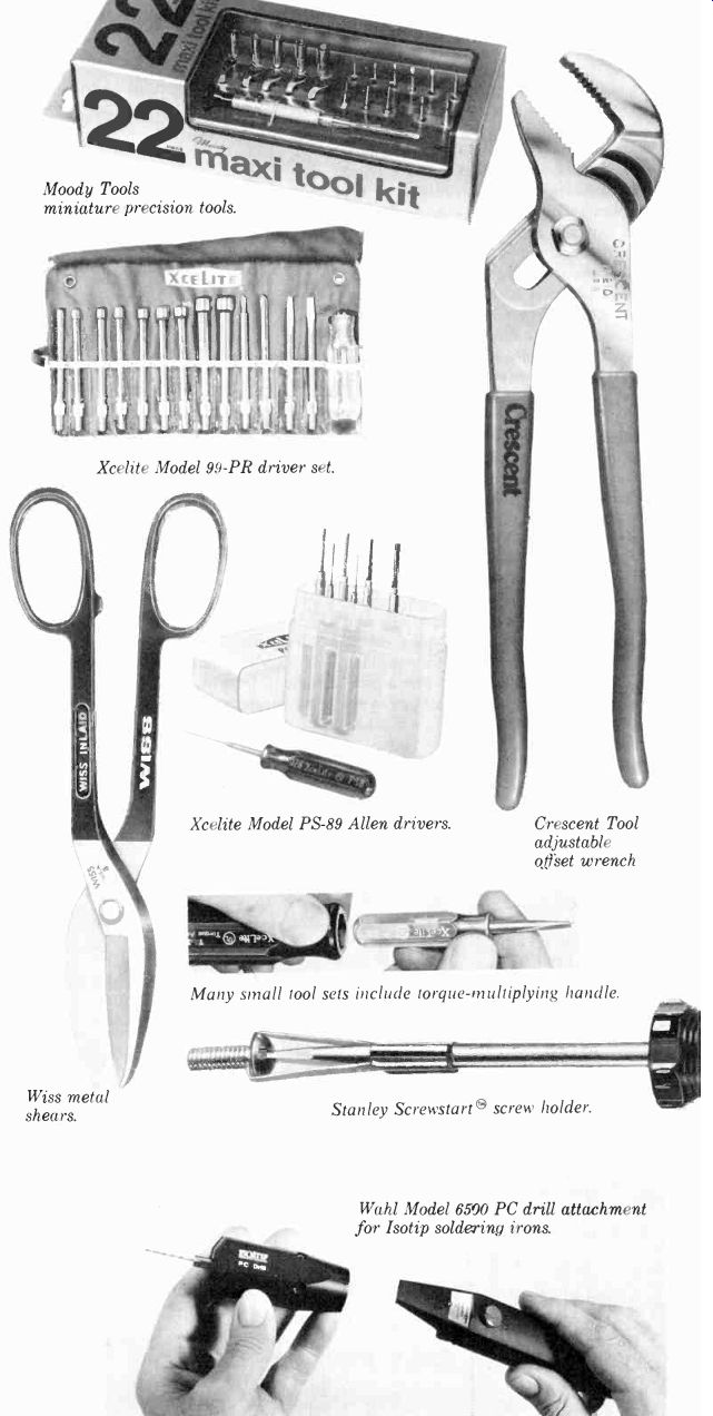
--------Moody Tools miniature precision tools.
--------Xcelite Model 99-PR driver set.
-------Wiss metal shears.
--------Xcelite Model PS-89 Allen drivers.
-------Crescent Tool adjustable offset wrench
-------Many small tool sets include torque-multiplying handle.
--------Stanley Screwstart screw holder.
--------Wahl Model 6590 PC drill attachment for Isotip soldering irons.
A metal nibbling tool can be used to make just about any needed chassis or panel opening. This tool starts at a pre-drilled hole and is guided along the area to be cut out, taking bite-size chunks out of the metal as it is moved along. Cutting a large hole in a piece of sheet metal can be a tedious procedure with a nibbling tool, but the nibbler will provide good results if care is taken in using it.
Drills. Perhaps the most commonly used metal-working tool from the electronics hobbyist's point of view is the electric drill. A drill for the electronics workbench should have a chuck capacity of 1/4 or 3/8 inch (6.4 or 9.5 mm) and should have variable-speed control.
(Slow speeds are ideal for starting holes and for drilling through soft materials.) The drill should also have either a three-conductor power cord and a metal body or a two-conductor cord and a double-insulated plastic body. Its motor should be rated at a minimum of 1/4 horsepower. For maximum user comfort, the drill should fit comfortably in the hand and should be well balanced.
The piece of metal that does the actual cutting of the material being drilled is called a drill bit. There are two general classes of drill bits-those composed of carbon steel and those composed of tungsten-molybdenum steel. The latter is called "high-speed steel" and is used in the manufacture of high-speed drill bits. Because of their superior cutting and wearing characteristics, high-speed bits are the clear choice for the electronics hobbyist. The most economical way to purchase an array of high-speed drill bits is in a set that includes units with diameters ranging from approximately 3/32 inch (2.4 mm) to 1/4 or 3/8 inch (6.4 or 9.5 mm).
Ancillary items for drilling and other metal work are a center punch, a ball-peen hammer, a reamer, a' heavy-duty bench vise and a set of files.
At least one center-punch is needed to make indentations in the material to be drilled at the exact centers of the holes to be made. These indentations will pre vent the bit from wandering around the surface when first brought up to speed.
A reamer is used to enlarge holes in sheet metal, and can also be used to remove burrs around the perimeter of a freshly drilled hole. General-duty work calls for a 12-inch (1.3-cm) tapered reamer. A heavy-duty bench vise will be needed if a lot of metal working will be done. It is very useful in holding chassis and other items as they are drilled or sawed. The jaws of the vise should be at least 2 inches long, and the vise should be a swivel unit which rotates in the horizontal plane. This will allow its jaws to form any desired angle with respect to the edge of the workbench.
At least four files should be kept on hand for metal work. Round, half-round, and "rat-tail" files are especially useful in opening up a hole or deburring. Most electronics metal work involves aluminum chassis. Because aluminum is relatively soft, coarse files are the best.
Miniature Power Tools. Hobbyists who do a lot of printed-circuit work will find most power tools to be too big and unwieldy. The answer to their problem is a miniature electric hand drill designed especially for pc applications. Among the companies that make such tools are Micro Electronics Systems, Weller, Dremel, and the Wahl Clipper Corporation.
Those printed-circuit enthusiasts who already have a Wahl "Isotip" cordless soldering iron will no doubt be interested in Wahl's Model 6500 PC Drill attachment. This unit plugs into the body of the soldering iron and converts it into a battery-powered electric drill with a No. 56 bit and an operating speed of 10,000 to 12,000 rpm. Wahl also makes specialized Electronics Technician Drills with collet chucks designed specifically for pc applications.
A good tool to use for circuit-board work is the Dremel Moto Tool high- speed drill and grinder, which comes in models ranging from the general-purpose Model 260 to the heavy-duty, vari able Model 380. Light in weight, the tool is easy to handle and accepts drill bits ranging from No. 80 to No. 30, depending on which of three chuck collets is to be used.
Another flexible hand-held power tool is the Weller Model 651K variable-speed Mini-Shop Kit. This kit includes a handheld power tool and a whole complement of drilling, grinding, polishing, sanding and cutting attachments.
Such mini-tools are not for everyone, but those who do a considerable amount of close circuit-board work wouldn't be without one.
In Conclusion. Hands-on personal electronics calls for a work area stocked with a considerable assortment of tools, test equipment, hardware, etc.
Some items are absolutely necessary; others are convenient and enhance work efficiency. Many implements can be found in any well-stocked hardware store. Others are specialty items that must be obtained from more exotic sources. Look into your needs now so that your future electronics work will be more enjoyable to pursue.
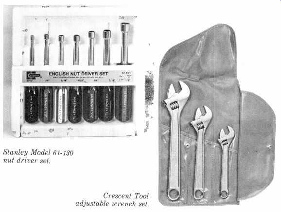
-------Stanley Model 61-130 nut driver set.
--------Crescent Tool adjustable wrench set.
Source: (Popular Electronics Electronic Experimenter's Handbook (1983)
Also see:
High Performance Scratch and Rumble Filters