Helpful tips on materials, tools, and techniques.
BY JOHN D. BORNEMAN
IN ELECTRONICS, the basic goal of soldering is to electrically and mechanically join two circuit components. For this connection to be reliable, the solder must adhere to or "wet" the mating surfaces of the components being joined. The wetting of solder to a base metal is similar to the action of water spilled on a smooth surface: if the surface is clean and free of dirt, wax and oils, the water will wet and spread evenly over it; if the surface is waxed, the water balls up.
Most manufacturers of electronic components do a good job of making their products of easily solderable material or providing a clean solderable coating. Copper, copper-clad steel, or nickel-steel are some of the common base metals used in the leads of resistors, capacitors, integrated circuits, etc., and they may be coated with silver, tin, tin-lead, or gold to improve solderability.
Greases, oils, dirt, and oxides are the principal sources of contamination that prevent good solder wetting despite the original surface. Also, aging deteriorates the surface, and inhibits solder wetting by the formation of oxide films.
Solder Alloys and Fluxes. Technically, soldering is the joining of two parts with a metal alloy having a melting point below 800°F. Various solder alloys include combinations of tin, lead, antimony, silver, indium, and bismuth; however, the most common combination is tin and lead. Tin-lead solders range from pure tin to pure lead and include all proportions in between. For plumbing, alloys of 10% tin and 90% lead (10/ 90 solder) are commonly used. In electrical soldering, the alloy mix 'is usually 60% tin and 40% lead (60/40).
Characteristics of alloys of tin and lead are plotted against temperature in Fig. 1. This graph, referred to as a phase diagram, allows one to see that only a 63/37 alloy has a eutectic point-that is, a single melting point. All other alloys start melting at one temperature, move through a "pasty" or semisolid stage, and then become liquid at a higher temperature. Any physical movement of the components being soldered while the solder is in the "pasty" range will result in a "cold" joint. Such a joint appears grainy and dull, and is mechanically weaker, thus less reliable. Therefore, 63/37 or 60/40 solder is commonly used in electronics since they do not remain long in a "pasty" phase. However, a 50/50 alloy can be used if proper care is taken.
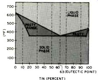
Fig. 1. Melting point, including pasty phase, of alloys of tin and copper.
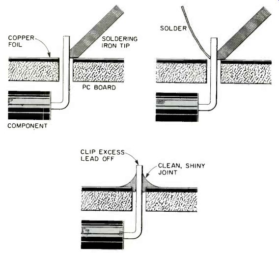
Fig. 2. Steps in soldering. Place heated iron to junction of parts to be
soldered (top left). Bring flux-cored solder to the joint after it is hot
enough to melt solder (top right).
When a smooth-contoured fillet has formed, remove the solder and allow to cool without moving.
An often-ignored aspect of soldering is the flux. The word flux comes from the Latin root "fluere" meaning "to flow." Soldering flux, which is usually included in the solder as a central core, or separately in liquid or paste form, helps the solder alloy flow around the connection. Flux also cleans the component leads of oxides and films, and allows the solder to wet their surfaces.
Chemically, flux is either acid or rosin based. Always use rosin flux in electronic soldering since the acid may cause corrosion. "Activated" rosin or "RA" flux produces better cleaning and flowing properties than the popular mildly activated fluxes (RMA), and they are noncorrosive.
Equipment. The tools required to solder electrical connections are: a good soldering iron and a supply of replaceable tips, long-nose pliers for holding parts or bending leads (or as a heat sink for temperature-sensitive components), and desoldering braid (or a suction de-soldering tool). There are basically two types of soldering instruments-the "gun" and the "iron," although most people use these descriptions interchangeably. In essence, a soldering "gun" is a pistol-shaped device consisting of a transformer forming the bulk of the "gun," with the secondary winding extending out to form the replaceable tip. Usually, soldering guns come with high wattages, in most cases too high for use with pc foil patterns. Such guns also generate a high magnetic field around the tip that can de-gauss any magnetically sensitive devices close to it. Using a gun may produce too high a heat on the foil pattern so that the cement that secures the copper foil pattern to the substrate is weakened and the foil separates from the printed circuit board.
The "iron" is often called a "pencil iron" because it resembles a thick pencil that is held in the fingers. These tools feature interchangeable (usually screw-on) tips having various shapes-each for its own purpose. Their wattages are usually low enough to be safely used on pc boards. The latest version of the pencil iron is the low-wattage self-contained rechargeable type that can be used remote from the ac line.
Soldering irons are specified primarily by wattage as shown in the table.
Wattage represents the amount of heat capacity available at the iron tip. Irons of all wattages usually run at about the same tip temperature, but a lower-wattage iron will cool faster during soldering. The recommended wattages given in the table are to be used as general guidelines only. Slight variations may give perfectly good performance, depending on the particular soldering situation. A higher-wattage iron is more likely to damage heat-sensitive components. If static-sensitive components are to be soldered, i.e. many MOS devices, be sure the iron has a grounded plug.
Soldering irons can produce static voltage spikes that will destroy many integrated circuit components, so a grounded tip is a wise safety measure.
Tips are usually selected by preference. Each type and shape has its place and purpose, but the commonly used pointed, conical type is the most versatile and convenient.
Desoldering equipment is always useful even for experienced solderers. Both braid and suction devices arc effective and, again, operator preference is the best guide. If you elect to use a suction desoldering tool, pay close attention to the distance and velocity that the "piston" requires. It is very easy to get a black eye, or have glasses damaged, when using those devices.
Soldering Techniques. The best technique can be outlined simply. First, make sure that the tip of the iron is at operating temperature, and is clean.
Then touch the heated tip to the connection, preferably on the part having the larger mass (Fig. 2). The solder should not be brought to the joint until the metals being joined have become hot enough to melt it. How long this takes is quickly learned after a few trials. The flux-cored solder is then brought to the joint and placed at the junction of the two parts. When the solder has melted and flowed into a smooth-contoured fillet, remove the solder. Keep the tip on the joint for a few seconds, then remove it. Do not disturb the newly made connection until it has had time to solidify. A good solder joint will be shiny (Fig. 3). Disturbing the joint before it has solidified may produce a "cold" joint.
Problem Solving.
To Avoid Cold Joints. Even when you know that the parts should not be moved while the solder joint is cooling, it is sometimes difficult to find enough hands to hold a soldering iron, solder, circuit board, and the part being attached. In this case, a small vise or a surgeon's hemostat may be used to hold the board and parts. If you are using rosin flux in liquid or paste form, another method is possible. Using long-nose pliers, hold the part to the circuit board.
Apply flux to the pieces being soldered and take up the soldering iron. Touch the iron to a length of solder, creating a ball on the tip. Touch the tip to the connection and hold it there until the fillet is formed. This will create a good joint and free your hands to hold the parts.
To Get Good Solder Wetting. Clean the parts well with isopropyl alcohol to remove greases and oils, and use a 10% solution of hydrochloric acid (HCl) to remove the oxides. Fine steel wool may be used on foil patterns to remove oxide films. These chemicals should be available from any drugstore, but remember to ask about any handling precautions before using them. Note that extra liquid flux can also help in soldering contaminated parts.
To Make Solder Flow. Be sure the soldering iron is providing enough heat, with the iron tip on tight and the proper wattage being used. Also be sure enough flux has reached the component leads and that it is not necessary to add extra liquid or past flux. Do not keep the iron on the joint or continue adding solder if a connection is not made after two trials. This will only damage the components or the circuit board.
To Solder ICs and Other Small Components. Use only a low-wattage iron and sharp tip to avoid excess heat. Also, use 0.031-inch diameter solder to help control the amount of solder deposited.
Provide a heat sink by using long-nose pliers to grasp the lead between the component package and the portion to be soldered.
After completely soldering a pc board, an inspection of the soldered joints is suggested. A toenail clipper can be used to trim any lead ends so they don't protrude too far from the solder.
To help in the inspection, a bright spotlight and low-power lens can be used to examine each joint. A sharp tool can clear away dross, solder bridges, or anything that looks suspicious between solder pads, and a toothbrush can be used to clean the solder joint. To make sure that all joints are checked, a drop of red nail polish can be placed on each after inspection. A minute spent checking a board can save an hour of troubleshooting later on.
Another problem can arise when a plastic capacitor appears to be "soldered" in place, but is not making an electrical connection. This often happens when a small "sleeve" of nonconducting plastic extends from the capacitor body slightly down each lead. The solder will hold the plastic to the pad, but an electrical connection may not result. Use long-nose pliers to break away the unwanted plastic.
Since your fingers may be dirty or oily, handle parts and circuit boards as little as possible. If there is any question of oily spots on a part, clean it using isopropyl alcohol or fine steel wool. If you use steel wool, use lint-free cloth to remove all vestiges of the wool from the parts or board.
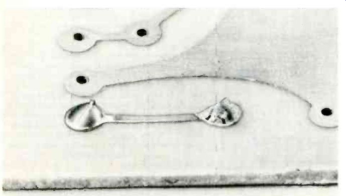
Fig. 3. Photo of two soldered joints. The one at left is shiny indicating
a good joint. At right, is a "cold" solder joint.
============
IRON WATTAGES FOR DIFFERENT SOLDERING TASKS
----------
Type of Soldering
Light duty: single joints, repair, touchup, delicate parts such as ICs or fine wires. Mass of parts in connection is small.
Medium duty: multiple joints; many in succession. Mass of parts is intermediate (for example, 1/4-watt resistors or conventional disc capacitors).
Heavy duty: Mass is large, as in wires soldered to steel case or wires to screw head,; for ground points.
-------------
Recommended Iron Wattage
25 to 30
60 to 100
over 100
===========
To Summarize:
(1) Use clean new parts and circuit boards.
(2) Use 60/40 or 50/50 tin-lead alloy solder with an activated rosin core. Liquid or paste rosin flux may be used to improve wetting when necessary.
(3) Use the proper wattage soldering iron based on the amount of soldering to be done and the type of components being soldered.
(4) Use the proper soldering sequence-tip to parts, solder to parts--solder away from parts--tip away from parts.
(5) Use patience.
(6) Practice.
Source: Computers and Electronics--Experimenter's Handbook (1984)
Also see: Tools & Equipment for Electronic Workbenches
Build ‘LIDITH' -- A 3½-Digit Digital Thermometer