In the view of many observers, compared to newer coding methods, linear pulse-code modulation (PCM) is a powerful but inefficient dinosaur. Because of its gargantuan appetite for bits, PCM coding is not suitable for many audio applications. There is an intense desire to achieve lower bit rates because low bit-rate coding opens so many new applications for digital audio (and video). Responding to the need, audio engineers have devised many lossy and lossless codecs. Some codecs use proprietary designs that are kept secret, some are described in standards that can be licensed, while others are open source. In any case, it would be difficult to overstate the importance of low bit rate codecs. Codecs can be found in countless products used in everyday life, and their development is largely responsible for the rapidly expanding use of digital audio techniques in storage and transmission applications.
Early Codecs
Although the history of perceptual codecs is relatively brief, several important coding methods have been developed, which in turn inspired the development of more advanced methods. Because of the rapid development of the field, most early codecs are no longer widely used, but they established methods and benchmarks on which modern codecs are based.
MUSICAM (Masking pattern adapted Universal Subband Integrated Coding And Multiplexing) was an early perceptual coding algorithm that achieved data reduction based on subband analysis and psychoacoustic principles.
Derived from MASCAM (Masking pattern Adapted Subband Coding And Multiplexing), MUSICAM divides the input audio signal into 32 subbands with a polyphase filter bank. With a sampling frequency of 48 kHz, the subbands are each 750 Hz wide. A fast Fourier transform (FFT) analysis supplies spectral data to a perceptual coding model; it uses the absolute hearing threshold and masking to calculate the minimum signal-to-mask ratio (SMR) value in each subband. Each subband is given a 6-bit scale factor according to the peak value in the subband's 12 samples and quantized with a variable word ranging from 0 to 15 bits. Scale factors are calculated over a 24-ms interval, corresponding to 36 samples. A subband is quantized only if it contains audible signals above the masking threshold. Subbands with signals well above the threshold are coded with more bits. In other words, within a given bit rate, bits are assigned where they are most needed. The data rate is reduced to perhaps 128 kbps per monaural channel (256 kbps for stereo). Extensive tests of 128 kbps MUSICAM showed that the codec achieves fidelity that is indistinguishable from a CD source, that it is monophonically compatible, that at least two cascaded codec stages produce no audible degradation, and that it is preferred to very high-quality FM signals. In addition, a bit-error rate of up to 10-3 was nearly imperceptible.
MUSICAM was developed by CCETT, IRT, Matsushita, and Philips.
OCF (Optimal Coding in the Frequency domain) and PXFM (Perceptual Transform Coding) are similar perceptual transform codecs. A later version of OCF uses a modified discrete cosine transform (MDCT) with a block length of 512 samples and a 1024-sample window. PXFM uses an FFT with a block length of 2048 samples and an overlap of 1/16. PXFM uses critical-band analysis of the signal's power spectrum, tonality estimation, and a spreading function to calculate the masking threshold.
PXFM uses a rate loop to optimize quantization. A stereo version of PXFM further takes advantage of correlation in the frequency domain between left and right channels. OCF uses an analysis-by-synthesis method with two iteration loops. An outer (distortion) loop adjusts quantization step size to ensure that quantization noise is below the masking threshold in each critical band. An inner (rate) loop uses a nonuniform quantizer and Huffman coding to optimize the word length needed to quantize spectral values. OCF was devised by Karlheinz Brandenburg in 1987, and PXFM was devised by James Johnston in 1988.
The ASPEC (Audio Spectral Perceptual Entropy Coding) standard described a MDCT transform codec with relatively high complexity and the ability to code audio for low bit-rate applications such as ISDN. ASPEC was developed jointly using work by AT&T Bell Laboratories, Fraunhofer Institute, Thomson, and CNET.
MPEG-1 Audio Standard
The International Organization for Standardization (ISO) and the International Electrotechnical Commission (IEC) formed the Moving Picture Experts Group (MPEG) in 1988 to devise data reduction techniques for audio and video.
MPEG is a working group of the ISO/IEC and is formally known as ISO/IEC JTC 1/SC 29/WG 11; MPEG documents are published under this nomenclature. The MPEG group has developed several codec standards. It first devised the ISO/IEC International Standard 11172 "Coding of Moving Pictures and Associated Audio for Digital Storage Media at up to about 1.5 Mbit/s" for reduced data rate coding of digital video and audio signals; the standard was finalized in November 1992. It is commonly known as MPEG-1 (the acronym is pronounced "m-peg") and was the first international standard for the perceptual coding of high quality audio.
The MPEG-1 standard has three major parts: system (multiplexed video and audio), video, and audio; a fourth part defines conformance testing. The maximum audio bit rate is set at 1.856 Mbps. The audio portion of the standard (11172-3) has found many applications. It supports coding of 32-, 44.1-, and 48-kHz PCM input data and output bit rates ranging from approximately 32 kbps to 224 kbps/channel (64 kbps to 448 kbps for stereo). Because data networks use data rates of 64 kbps (8 bits sampled at 8 kHz), most codecs output a data channel rate that is a multiple of 64.
The MPEG-1 standard was originally developed to support audio and video coding for CD playback within the CD's bandwidth of 1.41 Mbps. However, the audio standard supports a range of bit rates as well as monaural coding, dual-channel monaural coding, and stereo coding.
In addition, in the joint-stereo mode, stereophonic irrelevance and redundancy can be optionally exploited to reduce the bit rate. Stereo audio bit rates below 256 kbps are useful for applications requiring more than two audio channels while maintaining full-screen motion video. Rates above 256 kbps are useful for applications requiring higher audio quality, and partial screen video images. In either case, the bit allocation is dynamically adaptable according to need. The MPEG-1 audio standard is based on data reduction algorithms such as MUSICAM and ASPEC.
Development of the audio portion of the MPEG-1 audio standard was greatly influenced by tests conducted by Swedish Radio in July 1990. MUSICAM coding was judged superior in complexity and coding delay. However, the ASPEC transform codec provided superior sound quality at low data rates. The architectures of the MUSICAM and ASPEC coding methods formed the basis for the ISO/MPEG-1 audio standard with MUSICAM describing Layers I and II and ASPEC describing Layer III. The 11172 3 standard describes three layers of audio coding, each with different applications. Specifically, Layer I describes the least sophisticated method that requires relatively high data rates (approximately 192 kbps/channel). Layer II is based on Layer I but is more complex and operates at somewhat lower data rates (approximately 96 kbps to 128 kbps/channel). Layer I IA is a joint-stereo version operating at 128 kbps and 192 kbps per stereo pair. Layer III is somewhat conceptually different from I and II , is the most sophisticated, and operates at the lowest data rate (approximately 64 kbps/channel). The increased complexity from Layer I to III is reflected in the fact that at low data rates, Layer III will perform best for audio fidelity. Generally, Layers II , I IA, and III have been judged to be acceptable for some broadcast applications; in other words, operation at 128 kbps/channel does not impair the quality of the original audio signal. The three layers (I , II , and III ) all refer to audio coding and should not be confused with different MPEG standards such as MPEG-1 and MPEG-2.
In very general terms, all three layer codecs operate similarly. The audio signal passes through a filter bank and is analyzed in the frequency domain. The sub-sampled components are regarded as subband values, or spectral coefficients. The output of a side-chain transform, or the filter bank itself, is used to estimate masking thresholds.
The subband values or spectral coefficients are quantized according to a psychoacoustic model. Coded mapped samples and bit allocation information are packed into frames prior to transmission. In each case, the encoders are not defined by the MPEG-1 standard, only the decoders are specified. This forward-adaptive bit allocation permits improvements in encoding methods, particularly in the psychoacoustic modeling, provided the data output from the encoder can be decoded according to the standard. In other words, existing codecs will play data from improved encoders.
The MPEG-1 layers support joint-stereo coding using intensity coding. Left/right high-frequency subband samples are summed into one channel but scale factors remain left/right independent. The decoder forms the envelopes of the original left and right channels using the scale factors.
The spectral shape of the left and right channels is the same in these upper subbands, but their amplitudes differ.
The bound for joint coding is selectable at four frequencies:
3, 6, 9, and 12 kHz at a 48-kHz sampling frequency; the bound can be changed from one frame to another. Care must be taken to avoid aliasing between subbands and negative correlation between channels when joint coding.
Layer III also supports M/S sum and difference coding between channels, as described below. Joint stereo coding increases codec complexity only slightly.
Listening tests demonstrated that either Layer II or III at 2 × 128 kbps or 192 kbps joint stereo can convey a stereo audio program with no audible degradation compared to a 16-bit PCM coding. If a higher data rate of 384 kbps is allowed, Layer I also achieves transparency compared to 16-bit PCM. At rates as low as 128 kbps, Layers II and III can convey stereo material that is subjectively very close to 16-bit fidelity. Tests also have studied the effects of cascading MPEG codecs. For example, in one experiment, critical audio material was passed through four Layer II codec stages at 192 kbps and two stages at 128 kbps, and they were found to be transparent. On the other hand, a cascade of five codec stages at 128 kbps was not transparent for all music programs. More specifically, a source reduced to 384 kbps with MPEG-1 Layer II sustained about 15 code/decodes before noise became significant; however, at 192 kbps, only two codings were possible. These particular tests did not enjoy the benefit of joint-stereo coding, and as with other perceptual codecs, performance can be improved by substituting new psychoacoustic models in the encoder.
The similarity between the MPEG-1 layers promotes tandem operation. For example, Layer III data can be transcoded to Layer II without returning to the analog domain (other digital processing is required, however). A full MPEG-1 decoder must be able to decode its layer, and all layers below it. There are also Layer X codecs that only code one layer. Layer I preserves highest fidelity for acquisition and production work at high bit rates where six or more codings can take place. Layer II distributes programs efficiently where two codings can occur. Layer III is most efficient, with lowest rates, with somewhat lower fidelity, and a single coding.
MPEG-2 incorporates the three audio layers of MPEG-1 and adds additional features, principally surround sound.
However, MPEG-2 decoders can play MPEG-1 audio files, and MPEG-1 two-channel decoders can decode stereo information from surround-sound MPEG-2 files.
MPEG Bitstream Format
In the MPEG elementary bitstream, data is transmitted in frames, as shown in FIG. 1. Each frame is individually decodable. The length of a frame depends on the particular layer and MPEG algorithm used. In MPEG-1, Layers II and III have the same frame length representing 1152 audio samples. Unlike the other layers, in Layer III the number of bits per frame can vary; this allocation provides flexibility according to the coding demands of the audio signal.
A frame begins with a 32-bit ISO header with a 12-bit synchronizing pattern and 20 bits of general data on layer, bit-rate index, sampling frequency, type of emphasis, and so on. This is followed by an optional 16-bit CRCC check word with generation polynomial x16 + x15 + x2 + 1.
Subsequent fields describe bit allocation data (number of bits used to code subband samples), scale factor selection data, and scale factors themselves. This varies from layer to layer. For example, Layer I sends a fixed 6-bit scale factor for each coded subband. Layer II examines scale factors and uses dynamic scale factor selection information (SCFSI ) to avoid redundancy; this reduces the scale factor bit rate by a factor of two.
The largest part of the frame is occupied by subband samples. Again, this content varies among layers. In Layer II , for example, samples are grouped in granules. The length of the field is determined by a bit-rate index, but the bit allocation determines the actual number of bits used to code the signal. If the frame length exceeds the number of bits allocated, the remainder of the frame can be occupied by ancillary data (this feature is used by MPEG-2, for example). Ancillary data is coded similarly to primary frame data. Frames contain 384 samples in Layer I and 1152 samples in II and III (or 8 ms and 24 ms, respectively, at a 48-kHz sampling frequency).

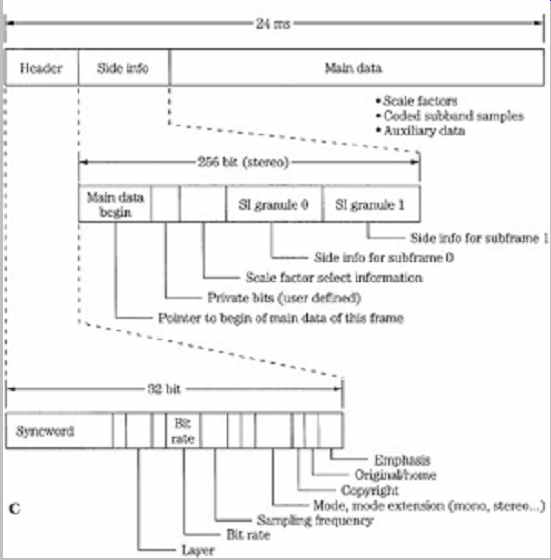
FIG. 1 Structure of the MPEG-1 audio Layer I , II , and III bitstreams.
The header and some other fields are common, but other fields differ. Higher-level
codecs can transcode lower-level bitstreams. A. Layer I bitstream format. B.
Layer II bitstream format. C. Layer III bitstream format.
MPEG-1 Layer I
The MPEG-1 Layer I codec is a simplified version of the MUSICAM codec. It is a subband codec, designed to provide high fidelity with low complexity, but at a high bit rate. Block diagrams of a Layer I encoder and decoder (which also applies to Layer II ) are shown in FIG. 2. A polyphase filter splits the wideband signal into 32 subbands of equal width. The filter is critically sampled; there is the same number of samples in the analyzed domain as in the time domain. Adjacent subbands overlap; a single frequency can affect two subbands. The filter and its inverse are not lossless; however, the error is small. The filter bank bands are all equal width, but the ear's critical bands are not; this is compensated for in the bit allocation algorithm. For example, lower bands are usually assigned more bits, increasing their resolution over higher bands.
This polyphase filter bank with 32 subbands is used in all three layers; Layer III adds additional hybrid processing.
The filter bank outputs 32 samples, one sample per band, for every 32 input samples. In Layer I , 12 subband samples from each of the 32 subbands are grouped to form a frame; this represents 384 wideband samples. At a 48-kHz sampling frequency, this comprises a block of 8 ms. Each subband group of 12 samples is given a bit allocation; subbands judged inaudible are given a zero allocation. Based on the calculated masking threshold (just audible noise), the bit allocation determines the number of bits used to quantize those samples. A floating-point notation is used to code samples; the mantissa determines resolution and the exponent determines dynamic range. A fixed scale factor exponent is computed for each subband with a nonzero allocation; it is based on the largest sample value in the subband. Each of the 12 subband samples in a block is normalized by dividing it by the same scale factor; this optimizes quantizer resolution.
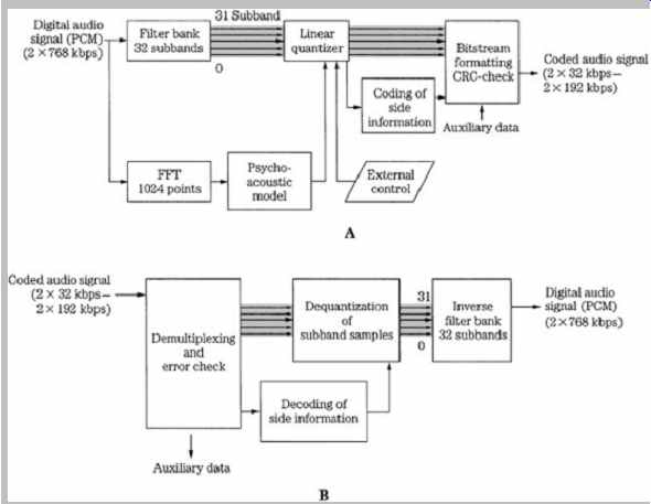
FIG. 2 MPEG-1 Layer I or II audio encoder and decoder. The 32-subband
filter bank is common to all three layers. A. Layer I or II encoder (single-channel
mode). B. Layer I or II two-channel decoder.
A 512-sample FFT wideband transform located in a side chain performs spectral analysis on the audio signal.
A psychoacoustic model, described in more detail later, uses a spreading function to emulate a basilar membrane response to establish masking contours and compute signal-to-mask ratios. Tonal and nontonal (noise-like) signals are distinguished. The psychoacoustic model compares the data to the minimum threshold curve. Using scale factor information, normalized samples are quantized by the bit allocator to achieve data reduction. The subband data is coded, not the FFT spectra.
Dynamic bit allocation assigns mantissa bits to the samples in each coded subband, or omits coding for inaudible subbands. Each sample is coded with one PCM codeword; the quantizer provides 2n-1 steps where 2 = n = 15.
Subbands with a large signal-to-mask ratio are iteratively given more bits; subbands with a small SMR value are given fewer bits. In other words, the SMR determines the minimum signal-to-noise ratio that has to be met by the quantization of the subband samples.
Quantization is performed iteratively. When available, additional bits are added to codewords to increase the signal-to-noise ratio (SNR) value above the minimum.
Because the long block size might expose quantization noise in a transient signal, coarse quantization is avoided in blocks of low-level audio that are adjacent to blocks of high-level (transient) audio. The block scale factor exponent and sample mantissas are output. Error correction and other information are added to the signal at the output of the codec.
Playback is accomplished by decoding the bit allocation information, and decoding the scale factors. Samples are requantized by multiplying them with the correct scale factor. The scale factors provide all the information needed to recalculate the masking thresholds. In other words, the decoder does not need a psychoacoustic model. Samples are applied to an inverse synthesis filter such that subbands are placed at the proper frequency and added, and the resulting broadband audio waveform is output in consecutive blocks of thirty-two 16-bit PCM samples.
Example of MPEG-1 Layer I Implementation
As with other perceptual coding methods, MPEG-1 Layer I uses the ear's audiology performance as its guide for audio encoding, relying on principles such as amplitude masking to encode a signal that is perceptually identical.
Generally, Layer I operating at 384 kbps achieves the same quality as a Layer II codec operating at 256 kbps.
Also, Layer I can be transcoded to Layer II . The following describes a simple Layer I implementation without a psychoacoustic model; its design is basic compared to other modern codecs.
PCM data with 32-, 44.1-, or 48-kHz sampling frequencies can be input to an encoder. At these three sampling frequencies, the subband width is 500, 689, and 750 Hz, and the frame period is 12, 8.7, and 8 ms, respectively. The following description assumes a 48-kHz sampling frequency. The stereo audio signal is passed to the first stage in a Layer I encoder, as shown in FIG. 3. A 24-bit finite impulse response (FIR) filter with the equivalent of 512 taps divides the audio band into 32 subbands of equal 750-Hz width. The filter window is shifted by 32 samples each time (12 shifts) so all the 384 samples in the 8-ms frame are analyzed. The filter bank outputs 32 subbands. With this filter, the effective sampling frequency of a subband is reduced by 32 to 1, for example, from a frequency of 48 kHz to 1.5 kHz. Although the channels are bandlimited, they are still in PCM representation at this point in the algorithm. The subbands are equal width, whereas the ear's critical bands are not. This can be compensated for by unequally allocating bits to the subbands; more bits are typically allocated to code signals in lower-frequency subbands.
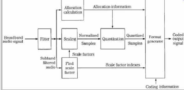
FIG. 3 Example of an MPEG-1 Layer I encoder. The FFT side chain is omitted.
The encoder analyzes the energy in each subband to determine which subbands contain audible information.
This example of a Layer I encoder does not use an FFT side chain or psychoacoustic model. The algorithm calculates average power levels in each subband over the 8-ms (12-sample) period. Masking levels in subbands and adjacent subbands are estimated. Minimum threshold levels are applied. Peak power levels in each subband are calculated and compared to masking levels. The SMR value (difference between the maximum signal and the masking threshold) is calculated for each sub-band and is used to determine the number of bits N assigned to a
subband (i) such that Ni = (SMRi -1.76)/6.02. A bit pool
approach is taken to optimally code signals within the given bit rate. Quantized values form a mantissa, with a possible range of 2 to 15 bits. Thus, a maximum resolution of 92 dB is available from this part of the coding word. In practice, in addition to signal strength, mantissa values also are affected by rate of change of the waveform pattern and available data capacity. In any event, new mantissa values are calculated for every sample period.
Audio samples are normalized (scaled) to optimally use the dynamic range of the quantizer. Specifically, six exponent bits form a scale factor, which is determined by the signal's largest absolute amplitude in a block. The scale factor acts as a multiplier to optimally adjust the gain of the samples for quantization. This scale factor covers the range from -118 dB to + 6 dB in 2-dB steps. Because the audio signal varies slowly in relation to the sampling frequency, the masking threshold and scale factors are calculated only once for every group of 12 samples, forming a frame (12 samples/subband × 32 subbands = 384 samples). For every subband, the absolute peak value of the 12 samples is compared to a table of scale factors, and the closest (next highest) constant is applied. The other sample values are normalized to that factor, and during decoding will be used as multipliers to compute the correct subband signal level.
A floating-point representation is used. One field contains a fixed-length 6-bit exponent, and another field contains a variable length 2- to 15-bit mantissa. Every block of 12 subband samples may have different mantissa lengths and values, but would share the same exponent.
Allocation information detailing the length of a mantissa is placed in a 4-bit field in each frame. Because the total number of bits representing each sample within a subband is constant, this allocation information (like the exponent) needs to be transmitted only once every 12 samples. A null allocation value is conveyed when a subband is not encoded; in this case neither exponent nor mantissa values within that subband are transmitted. The 15-bit mantissa yields a maximum signal-to-noise ratio of 92 dB. The 6-bit exponent can convey 64 values. However, a pattern of all 1's is not used, and another value is used as a reference.
There are thus 62 values, each representing 2-dB steps for an ideal total of 124 dB. The reference is used to divide this into two ranges, one from 0 to -118 dB, and the other from 0 to + 6 dB. The 6 dB of headroom is needed because a component in a single subband might have a peak amplitude 6 dB higher than the broadband composite audio signal. In this example, the broadband dynamic range is thus equivalent to 19 bits of linear coding.
A complete frame contains synchronization information, sample bits, scale factors, bit allocation information, and control bits for sampling frequency information, emphasis, and so on. The total number of bits in a frame (with two channels, with 384 samples, over 8 ms, sampled at 48 kHz) is 3072. This in turn yields a 384-kbps bit rate. With the addition of error detection and correction code, and modulation, the transmission bit rate might be 768 kbps.
The first set of subband samples in a frame is calculated from 512 samples by the 512-tap filter and the filter window is shifted by 32 samples each time into 11 more positions during a frame period. Thus, each frame incorporates information from 864 broadband audio samples per channel.
Sampling frequencies of 32 kHz and 44.1 kHz also are supported, and because the number of bands remains fixed at 32, the subband width becomes 689.06 Hz with a 44.1-kHz sampling frequency. In some applications, because the output bit rate is fixed at 384 kbps, and 384 samples/channel per frame is fixed, there is a reduction in frame rate at sampling frequencies of 32 kHz and 44.1 kHz, and thus an increase in the number of bits per frame. These additional bits per frame are used by the algorithm to further increase audio quality.
Layer I decoding proceeds frame by frame, using the processing shown in FIG. 4. Data is reformatted to PCM by a subband decoder, using allocation information and scale factors. Received scale factors are placed in an array with two columns of 32 rows, each six bits wide. Each column represents an output channel, and each row represents one subband. The decoded subband samples are multiplied by their scale factors to restore them to their quantized values; empty subbands are automatically assigned a zero value. A synthesis reconstruction filter recombines the 32 subbands into one broadband audio signal. This subband filter operates identically (but inversely) to the input filter. As in the encoder, 384 samples/channel represent 8 ms of audio signal (at a sampling frequency of 48 kHz). Following this subband filtering, the signal is ready for reproduction through D/A converters.
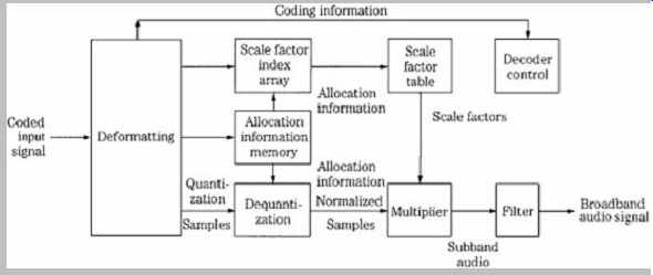
FIG. 4 Example of an MPEG-1 Layer I decoder.
Because psychoacoustic processing, bit allocation, and other operations are not used in the decoder, its cost is quite low. Also, the decoder is transparent to improvements in encoder technology. If encoders are improved, the resulting fidelity would improve as well. Because the encoding algorithm is a function of digital signal processing, more sophisticated coding is possible. For example, because the number of bits per frame varies according to sampling rate, it might be expedient to create different allocation tables for different sampling frequencies.
An FFT side chain would permit analysis of the spectral content of subbands and psychoacoustic modeling. For example, knowledge of where signals are placed within bands can be useful in more precisely assigning masking curves to adjacent bands. The encoding algorithm might assume signals are at band edges, the most conservative approach. Such an encoder might claim 18-bit performance. Subjectively, at a 384-kbps bit rate, most listeners are unable to differentiate between a simple Layer I recording and an original CD recording.
MPEG-1 Layer II
The MPEG-1 Layer II codec is essentially identical to the original MUSICAM codec (the frame headers differ). It is thus similar to Layer I , but is more sophisticated in design.
It provides high fidelity with somewhat higher complexity, at moderate bit rates. It is a sub-band codec. FIG. 5 gives a more detailed look at a Layer II encoder (which also applies to Layer I ). The filter bank creates 32 equal-width subbands, but the frame size is tripled to 3 × 12 × 32, corresponding to 1152 wideband samples per channel. In other words, data is coded in three groups of 12 samples for each subband (Layer I uses one group). At a sampling frequency of 48 kHz, this comprises a 24-ms period. FIG. 6 shows details of the subband filter bank calculation.
The FFT analysis block size is increased to 1024 points. In Layer II (and Layer III ) the psychoacoustic model performs two 1024-sample calculations for each 1152-sample frame, centering the first half and the second half of the frame, respectively. The results are compared and the values with the lower masking thresholds (higher SMR) in each band are used. Tonal (sinusoidal) and nontonal (noise-like) components are distinguished to determine their effect on the masking threshold.
A single bit allocation is given to each group of 12 subband samples. Up to three scale factors are calculated for each subband, each corresponding to a group of 12 sub-band samples and each representing a 2-dB step-size difference. However, to reduce the scale factor bit rate, the codec analyzes scale factors in three successive blocks in each subband. When differences are small or when temporal masking will occur, one scale factor can be shared between groups. When transient audio content is coded, two or three scale factors can be conveyed. Bit allocation is used to maximize both the subband and frame signal-to-mask ratios. Quantization covers a range from 3 to 65,535 (or none), but the number of available levels depends on the subband. Low-frequency subbands can receive as many as 15 bits, middle-frequency subbands can receive seven bits, and high-frequency subbands are limited to three bits. In each band, prominent signals are given longer codewords. It is recognized that quantization varies with subband number; higher subbands usually receive fewer bits, with larger step sizes. Thus for greater efficiency, three successive samples (for all 32 subbands) are grouped to form a granule and quantized together.
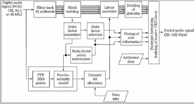
FIG. 5 MPEG-1 Layer II audio encoder (single channel mode) showing scale
factor selection and coding of side information.

FIG. 6 Flow chart of the analysis filter bank used in the MPEG-1 audio
standard.
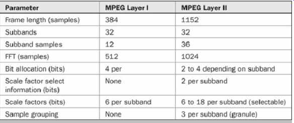
Table 1 Comparison of parameters in MPEG-1 Layer I and Layer II .
As in Layer I , decoding is relatively simple. The decoder unpacks the data frames and applies appropriate data to the reconstruction filter. Layer II coding can use stereo intensity coding. Layer II coding provides for a dynamic range control to adapt to different listening conditions, and uses a fixed-length data word. Minimum encoding and decoding delays are about 30 ms and 10 ms, respectively.
Layer II is used in some digital audio broadcasting (DAB) and digital video broadcasting (DVB) applications. Layer I and II are compared in Table 1. FIG. 7 shows a flow chart summarizing the complete MPEG-1 Layer I and II encoding algorithm.
MPEG-1 Layer III (MP3)
The MPEG-1 Layer III codec is based on the ASPEC codec and contains elements of MUSICAM, such as a subband filter bank, to provide compatibility with Layers I and II . Unlike the Layer I and II codecs, the Layer III codec is a transform codec. Its design is more complex than the other layer codecs. Its strength is moderate fidelity even at low data rates. Layer III files are popularly known as MP3 files. Block diagrams of a Layer III encoder and decoder are shown in FIG. 8.
As in Layers I and II , a wideband block of 1152 samples is first split into 32 subbands with a polyphase filter; this provides backward compatibility with Layers I and II . Each subband's contents are transformed into spectral coefficients by either a 6- or 18-point modified discrete cosine transform (MDCT) with 50% overlap (using a sine window) so that windows contain either 12 or 36 subband samples. The MDCT outputs a maximum of 32 × 18 = 576 spectral lines. The spectral lines are grouped into scale factor bands that emulate critical bands. At lower sampling frequencies optionally provided by MPEG-2, the frequency resolution is increased by a factor of two; at a 24-kHz sampling rate the resolution per spectral line is about 21 Hz. This allows better adaptation of scale factor bands to critical bands. This helps achieve good audio quality at lower bit rates.
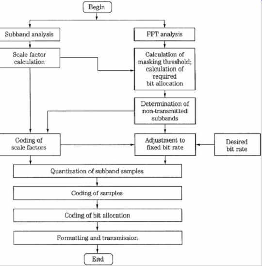
FIG. 7 Flow chart of the entire MPEG-1 Layer I and II audio encoding
algorithm.
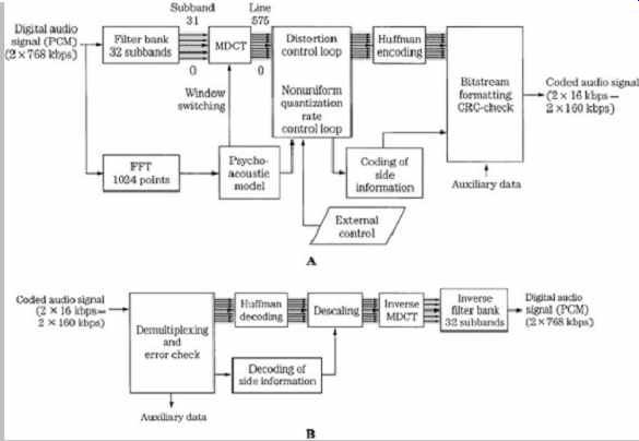
FIG. 8 MPEG-1 Layer III audio encoder and decoder.
A. Layer III encoder (single-channel mode). B. Layer III two channel decoder.
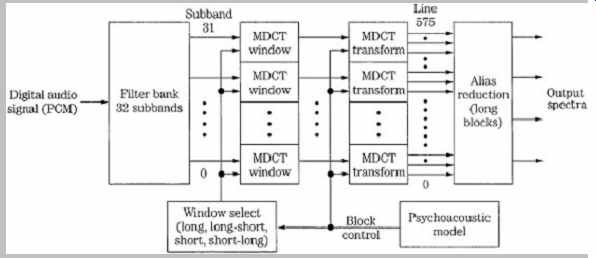
FIG. 9 Long and short blocks can be selected for the MDCT transform used
in the MPEG-1 Layer III encoder.
Both long and short windows, and two transitional windows, are used.
Layer III has high frequency resolution, but this dictates low time resolution. Quantization error spread over a window length can produce pre-echo artifacts. Thus, under direction of the psychoacoustic model, the MDCT window sizes can be switched between frequency or time resolution, using a threshold calculation; the architecture is shown in FIG. 9. A long symmetrical window is used for steady-state signals; a length of 1152 samples corresponds 24 ms at a 48-kHz sampling frequency. Each transform of 36 samples yields 18 spectral coefficients for each of 32 subbands, for a total of 576 coefficients. This provides good spectral resolution of 41.66 Hz (24000/576) that is needed for steady state-signals, at the expense of temporal resolution that is needed for transient signals.
Alternatively, when transient signals occur, a short symmetrical window is used with one-third the length of the long window, followed by an MDCT that is one-third length.
Time resolution is 4 ms at a 48-kHz sampling frequency.
Three short windows replace one long window, maintaining the same number of samples in a frame. This mode yields six coefficients per subband, or a total of 32 × 6 = 192 coefficients. Window length can be independently switched for each subband. Because the switchover is not instantaneous, an asymmetrical start window is used to switch from long to short windows, and an asymmetrical stop window switches back. This ensures alias cancellation. The four window types, along with a typical window sequence, are shown in FIG. 10. There are three block modes. In two modes, the outputs of all 32 subbands are processed through the MDCT with equal block lengths.
A mixed mode provides frequency resolution at lower frequencies and time resolution at higher frequencies.
During transients, the two lower subbands use long blocks and the upper 30 subbands use short blocks. Huffman coding is applied at the encoder output to additionally lower the bit rate.
A Layer III decoder performs Huffman decoding, as well as decoding of bit allocation information. Coefficients are applied to an inverse transform, and 32 subbands are combined in a synthesis filter to output a broadband signal.
The inverse modified discrete cosine transform (IMDCT) is executed 32 times for 18 spectral values each to transform the spectrum of 576 values into 18 consecutive spectra of length 32. These spectra are converted into the time domain by executing a polyphase synthesis filter bank 18 times. The polyphase filter bank contains a frequency mapping operation (such as matrix multiplication) and an FIR filter with 512 coefficients.
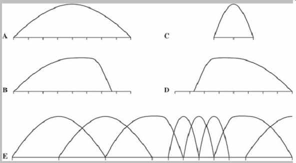
FIG. 10 MPEG-1 Layer III allows adaptive window switching for the MDCT
transform. Four window types are defined. A. Long (normal) window. B. Start
window (long to short). C. Short window. D. Stop window (short to long). D.
An example of a window sequence. (Brandenburg and Stoll, 1994)
MP3 files can be coded at a variety of bit rates.
However, the format is not scalable with respect to variable decoding. In other words, the decoder cannot selectively choose subsets of the entire bitstream to reproduce different quality signals.
MP3 Bit Allocation and Huffman Coding
The allocation control algorithm suggested for the Layer III encoder uses dynamic quantization. A noise allocation iteration loop is used to calculate optimal quantization noise in each subband. This technique is referred to as noise allocation, as opposed to bit allocation. Rather than allocate bits directly from SNR values, in noise allocation the bit assignment is an inherent outcome of the strategy.
For example, an analysis-by-synthesis method can be used to calculate a quantized spectrum that satisfies the noise requirements of the modeled masking threshold.
Quantization of this spectrum is iteratively adjusted so the bit rate limits are observed. Two nested iteration loops are used to find two values that are used in the allocation: the global gain value determines quantization step size, and scale factors determine noise-shaping factors for each scale factor band. To form scale factors, most of the 576 spectral lines in long windows are grouped into 21 scale factor bands, and most of the 192 lines from short windows are grouped into 12 scale factor bands. The grouping approximates critical bands, and varies according to sampling frequency.
An inner iteration loop (called the rate loop) acts to decrease the coder rate until it is sufficiently low. The Huffman code assigns shorter codewords to smaller quantized values that occur more frequently. If the resulting bit rate is too high, the rate loop adjusts gain to yield larger quantization step sizes and hence small quantized values and smaller Huffman codewords and a lower bit rate. The process of quantizing spectral lines and determining the appropriate Huffman code can be time-consuming. The outer iteration loop (called the noise control loop) uses analysis-by-synthesis to evaluate quantization noise levels and hence the quality of the coded signal. The outer loop decreases the quantizer step size to shape the quantization noise that will appear in the reconstructed signal, aiming to maintain it below the masking threshold in each band. This is done by iteratively increasing scale factor values. The algorithm uses the iterative values to compute the resulting quantization noise. If the quantization noise level in a band exceeds the masking threshold, the scale factor is adjusted to decrease the step size and lower the noise floor. The algorithm then recalculates the quantization noise level.
Ideally, the loops yield values such that the difference between the original spectral values and the quantized values results in noise below the masking threshold.
If the psychoacoustic model demands small step sizes and in contradiction the loops demand larger step sizes to meet a bit rate, the loops are terminated. To avoid this, the perceptual model can be modified and two loops tuned, to suit different bit rates; this tuning can require considerable development work. Nonuniform quantization is used such that step size varies with amplitude. Values are raised to the 3/4 power before quantizing to optimize the signal-to noise ratio over a range of quantizer values (the decoder reciprocates by raising values to the 4/3 power).
Huffman and run-length entropy coding exploit the statistical properties of the audio signal to achieve lossless data compression. Most audio frames will yield larger spectral values at low frequencies and smaller (or zero) values at higher frequencies. To utilize this, the 576 spectral lines are considered as three groups and can be coded with different Huffman code tables. The sections from low to high frequency are BIG_ VALUE, COUNT1, and RZERO, assigned according to pairs of absolute values ranging from 0 to 8191, quadruples of 0, -1, or + 1 values, and the pairs of 0 values, respectively. The BIG_VALUE pairs can be coded using any of 32 Huffman tables, and the COUNT1 quadruples can be coded with either of two tables. The RZERO pairs are not coded with Huffman coding. A Huffman table is selected based on the dynamic range of the values. Huffman coding is used for both scale factors and coefficients.
The data rate from frame to frame can vary in Layer III ; this can be used for variable bit-rate recording. The psychoacoustic model calculates how many bits are needed and sets the frame bit rate accordingly. In this way, for example, music passages that can be satisfactorily coded with fewer bits can yield frames with fewer bits. A variable bit rate is efficient for on-demand transmission.
However, variable bit rate streams cannot be transmitted in real time using systems with a constant bit rate. When a constant rate is required, Layer III can use an optional bit reservoir to allow for more accurate coding of particularly difficult (large perceptual entropy) short window passages.
In this way, the average transmitted data rate can be smaller than peak data rates. The number of bits per frame is variable, but has a constant long-term average. The mean bit rate is never allowed to exceed the fixed-channel capacity. In other words, there is reserve capacity in the reservoir. Unneeded bits (below the average) can be placed in the reservoir. When additional bits are needed (above the average), they are taken from the reservoir.
Succeeding frames are coded with somewhat fewer bits than average to replenish the reservoir. Bits can only be borrowed from past frames; bits cannot be borrowed from future frames. The buffer memory adds throughput time to the codec. To achieve synchronization at the decoder, headers and side information are conveyed at the frame rate. Frame size is variable; boundaries of main data blocks can vary whereas the frame headers are at fixed locations. Each frame has a synchronization pattern and subsequent side information discloses where a main data block began in the frame. In this way, main data blocks can be interrupted by frame headers.
In some codecs, the output file size is different from the input file size, and the signals are not time-aligned; the time duration of the codec's signal is usually longer. This is because of the block structure of the processing, coding delays, and the look-ahead strategies employed. Moreover, for example, an encoder might either discard a final frame that is not completely filled at the end of a file, or more typically pad the last frame with zeros. To maintain the original file size and time alignment, some codecs use ancillary data in the bitstream in a technique known as original file length (OFL). By specifying the number of samples to be stripped at the start of a file, and the length of the original file, the number of samples to be stripped at the end can be calculated. The OFL feature is available in the MP3PRO codec.