THE weak signal voltages at the output of the microphone, pick-up or tape recorder have to be increased in magnitude, altered in response to suit the acoustics of the listening room, and finally changed into power for adequate operation of the loudspeaker. The hi-fi amplifier system is required to perform these functions without changing the character of the original signal to any large degree, whilst also maintaining a level response over the whole of the audio spectrum and catering for a wide range of signal levels, from the smallest to the largest, without distortion. The dynamic range of a program signal may well extend to the region of 60 db, which means that the signal range in terms of input voltage may extend from 2 microvolts to 2 millivolts, resulting in a few milliwatts of output from the loudspeaker on the quietest signal or several watts on the loudest signal.
The first duty of the amplifier is to step-up the signal voltage to a level suitable for operating the output stage, or power-amplifier section. Bearing in mind that the power amplifier may require a signal level approaching 1.5 volts to fall within its driving range and that the program signal may only average 1 millivolt, one can clearly realize the necessity of voltage amplification of some 70 db.
At this juncture we should note that the term "voltage amplifier" indicates that the re-creation of the amplified input signal across a comparatively high impedance load is the essential function of this section.
Obviously, since an infinite output impedance does not exist in practice, it must be concerned also with the amplification of power. However, the output impedance is usually of the order of 0.1 to 1 megohm, so voltage is the pre dominant factor. We need not consider here when an amplifier ceases to be concerned with voltage and changes over to power, but simply regard power amplifiers as those used to drive a loudspeaker.
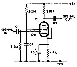
Fig. 2.1. Pentode voltage-amplifier stage.
A typical pentode voltage amplifier is shown in Fig. 2.1. There is nothing about this circuit as it appears on paper to indicate that it is associated with hi-fi equipment. In practice, however, it will be found that possibly the anode and grid resistors are of the "low noise" variety, also the valve (i.e. Mullard EF 86 or GEC Z729-low-noise types). Careful choice of circuit parameters ensures that the stage is operating at the lowest distortion figure within its voltage range. Hum problems are also taken care of by the use of carefully placed wiring, and by having a common "earthing" point so as to avoid producing common impedances across which hum voltages may develop.
A triode voltage amplifier is shown in Fig. 2.2. In practice, V1 is usually one half of a double-triode valve, the other half being employed also in the voltage amplifier, with a frequency-selective feedback loop (usually switched)
providing various degrees of equalization. This method is adopted in the Pye "Proctor" pre-amplifier. Generally speaking, there is little to choose between a modern pentode and triode. Greater gain is usually possible from the pentode, though such a stage does not give such freedom from intermodulation distortion at high output voltages as does the triode. Nevertheless, this is of little moment when the signal to be handled is of very low level.
NOISE AND HUM
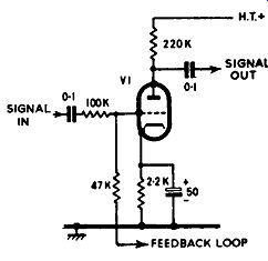
FIG. 2.2. Typical triode voltage-amplifier stage. V1 usually comprises
one half of a double-triode, the other half-section being used to complete
the stage. A frequency selective feedback loop may also be used for the
purpose of equalization.
Owing to the very low level of the signals to be amplified by the first stage, a problem peculiar to this section is that of "noise". Noise in this sense refers to all spurious disturbances which give rise to unwanted and undesirable signals across the output load along with the required signal. Since a quiet orchestral passage may give rise to only a few microvolts of signal across a pick-up or the playback head of a tape recorder, the stage will obviously be susceptible to the pick-up of stray hum signals and noise caused by in correct or faulty components.
Ideally, the only noise voltage which should be present with the signal across the output load is that attributable to the random behavior of electrons in the resistive components and in the valve. This is sometimes referred to as white noise, and is characterized by the hiss which emanates from the loudspeaker when the volume control of a very high-gain amplifier is turned full on. White noise is not confined to any particular frequency, but is distributed throughout the entire spectrum. If the equipment has peaks over--its response, the effect of the noise will be considerably emphasized at the frequencies corresponding to the peaks. Because our ears tend to "peak" around 3 khz, white noise resolves as a hiss, focused on 3 khz. An interesting test is to apply white noise to the input of a hi-fi amplifier by way of switched filters serving to attenuate progressively the high- and low-frequency components of the noise. A filter tuned to around 600 hz changes the hiss to a whistle, while a filter tuned to the low-frequency end of the spectrum gives rise to a roar.
With practice, white-noise tests of this nature permit rapid appraisal of the performance of hi-fi equipment, particularly if an oscilloscope can be used in the tests (remembering that the character of white noise is rather like that of transients, about which more will be said later). Unfortunately, apart from white noise, there often exist other and more disturbing spurious signals across the output load of the voltage amplifier.
Hum is a big bugbear in this connection. Hum poses much more of a problem in hi-fi equipment than in ordinary domestic radios of limited low-frequency response. In the first stage, hum is invariably induced into the input circuit from either stray electromagnetic or electrostatic fields. In most hi-fi amplifiers, the control-grid circuit of the voltage amplifier is reached by way of the program-selector switch, which gives the positions "gram", "tape" and "mic". Hum caused by stray fields will diminish on backing-off the volume control, since the control is usually located in the circuit following the output of the voltage amplifier. Operating the selector switch also gives conclusive evidence as to whether the hum pick-up is common to all circuits or a short coming of one particular channel. If the amplifier is in good order, as can nearly always be proved by these simple tests, it is safe to assume that the hum signal is gaining admittance either by way of the leads connecting to the various sources of program signal or by way of the external units themselves.
Electromagnetic induction occurs mainly in circuits of low impedance, and demands a complete loop into which induction can occur. For example, a low-impedance magnetic pick-up may enter an electromagnetic hum field as it traverses the turntable. The hum field may emanate from the gram motor or from a power transformer situated nearby. Whatever the cause, a small voltage (in terms of microvolts) will circulate the circuit comprising the pick up coil and the primary of the matching transformer, but this voltage will appear at the grid of the valve stepped up in the same ratio as the matching transformer. Thus, an induced voltage as small as 2 microvolts will rise to 100 microvolts at the grid with a transformer having a turns ratio of 50:1, which is a reasonable value for an input transformer.
Electromagnetic induction of a similar nature may well occur in a low impedance microphone circuit, in the circuit of the playback head of a tape recorder, or even at the coupling transformer. The overall loop effect can be obviated by employing either a tightly twisted pair of conductors or a coaxial line between the program signal source and the low-impedance amplifier input. There is little purpose in using parallel conductors as these aggravate the loop effect, and a screening over such conductors offers little or no protection against electromagnetic fields.
The susceptibility of the inductor at the low-impedance signal source (such as the winding and core associated with a low-impedance magnetic pick-up) and the coupling transformer at the amplifier end in responding to electromagnetic fields, particularly those at mains frequency (50 hz), can be reduced or almost eliminated by the use of high-permeability magnetic shields. The effect of such a shield at low frequency is shown in Fig. 2.3.
Where higher-frequency electromagnetic fields are present, more elaborate screening is usually called for. With a microphone transformer, for instance, it is often necessary to house it in a case formed of several shields, two of the type described and an intermediate one which operates by inducing into itself a field which opposes the offending field.
Electrostatic induction rarely affects low-impedance circuits, since the electrostatic charge is quickly dissipated around the low-impedance loop. However, in the case of a low-impedance circuit isolated from chassis, an electrostatic noise charge may appear at the grid as the result of the charge developing between the low-impedance circuit as an entirety and chassis.
This can usually be cleared simply by earthing the low-impedance side of the circuit, preferably at a center-tap on the primary of the transformer.
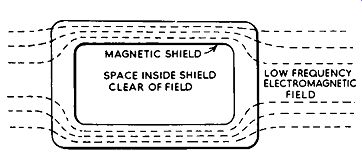
FIG. 2.3. A magnetic shield serves to protect the transformer or inductor
from stray electro magnetic fields.
Long lines between the program source and the input of the amplifier should always be avoided if hum is to be kept at the lowest level. If some reason or other necessitates long leads, then 600-ohm transformers should be employed either side of the line, that is at the program source and at the amplifier. In this way the danger of introducing hum due to different earth points can be avoided.
High-impedance connecting links should always comprise shielded cable having a low value of capacitance, bearing in mind that excessive capacitance at high impedance will impair considerably the high-frequency response of the program signal. Television coaxial cable can be used successfully for this purpose, but if the lead is extra long and is liable to be moved about a lot-for example, if it is used as a trailing high-impedance microphone cable--microphony effects may become troublesome. These resolve as the result of small changes in resistance of the outer conductor as the cable is moved and give rise to a "brushing" noise from the loudspeaker. If the cable is dropped, the effect from the loudspeaker is similar to that obtained by tapping the microphone.
Enthusiasts living close to a powerful television transmitter often complain of hum caused by the pick-up of the vision signals. In some cases the sound transmission is also troublesome. This unwanted pick-up gains admittance to the equipment either at the input circuits of the voltage amplifier or on the negative-feedback loop, by way of the speaker leads. It can be cured without difficulty by the insertion of a television choke in the speaker leads, as close as possible to the amplifier, or in the control-grid circuit of the voltage-amplifier valve, as close as possible to the grid tag. A choke (or chokes) can easily be made up by forming a self-supporting coil from 18 s.w.g. tinned copper wire, with the wire equal in length to that of a quarter wavelength of the frequency of the offending signal (67 inches for Channel 1, 59 inches for Channel 2, 53.5 inches for Channel 3, 49 inches for Channel 4, and 45.25 inches for Channel 5). IT A stations have not yet been reported as responsible, possibly because of the higher frequency used.
Trouble similar to this was reported on a hospital call system. In this case, though, the pick-up was from the v.h.f. transmitter employed in ambulances. The trouble was cured by the insertion of chokes and the making good of poor connections on the call-system microphone. In the latter respect, the trouble was being aggravated by rectification (demodulation) of the signal caused by high-resistance joints.
VALVE MICROPHONY
Valve microphony is another factor which affects the voltage amplifier.
The effects are ringing from the loudspeaker and a definite "ping" when the valve is tapped with a finger. Essentially, the trouble is caused by vibration of the electrode structure, promoting corresponding signal fluctuations across the anode-load resistor. High-slope triode valves are more susceptible to the effect than pentodes, particularly older-type triodes. Modern valves are less prone to the trouble, and circuit techniques help, as in these days it is not common practice to run the valve for maximum gain. Microphony is aggravated by vibrations from the loudspeaker, particularly when the speaker is situated in the same cabinet as the amplifier.
After the first amplifier stage, the signal is usually large enough not to be affected by problems of noise, since then the noise voltage is a very small ratio of the signal voltage. Apart from signal amplification, the duty of the first stage is that of securing the highest possible signal-to-noise ratio, and this is no mean task when it is considered that the applied signal voltage may well have a magnitude of only a few microvolts on soft passages of music.
As an aid in maintaining a good signal-to-noise ratio, the full signal voltage is invariably applied to the control grid of the first valve; the volume control being introduced after initial amplification when the signal is at much higher level. There are times, however, when the program signal itself is at high level; for instance, when a high-output pick-up is used or when an amplifier is incorporated in a radio tuner or tape recorder. When this is the case, some form of attenuation is needed between the program source and the amplifier input to avoid overloading the first valve.
FEEDBACK
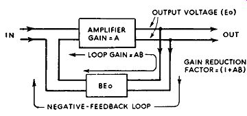
FIG. 2.4. Block diagram showing the application of negative feedback
to an amplifier.
One cannot progress far into hi-fi before coming up against feedback.
There are two kinds of feedback, positive and negative. Positive feedback means that a portion of the output signal of an amplifier is fed back to the input in the same phase as the applied signal. The application of positive feedback results in an increase in gain of the amplifier, and instability and oscillation when the feedback exceeds a certain degree. Positive feedback is the modus operandi of oscillator circuits. Negative feedback, on the other hand, results in degeneration, and is arranged by feeding back a portion of the output signal in opposite phase to the applied signal.
There are also two modes of feedback, current and voltage. The former occurs when the feedback voltage is proportional to the output current, and the latter when the feedback voltage is proportional to the output voltage.
The most common method of obtaining current feedback is by the use of an un-bypassed cathode resistor in a valve amplifier. Here, the signal voltage across. the cathode resistor, being in proportion to the current, is reflected anti-phase into the control-grid circuit.
Now for a few simple expressions.
The gain of an amplifier stage is reduced by the omission of the cathode capacitor by the factor (I + µ.}
+ Rk ----- +z ra
where Rk is the cathode resistor, µ. and ra are the amplification factor and a.c. resistance of the valve, and Z is the anode coupling impedance. The expression can be reduced to I+ g Rk where g is the mutal conductance of the valve, when ra is large compared with Z, as is often the case with pentode valves.
The block diagram in Fig. 2.4 represents an amplifier with a negative feedback loop. Writing A for the gain of the amplifier without feedback, and B for the fraction of the output voltage fed back, it can be stated that Gain with feedback = 1 A +AB
The factor (I + AB) is known as the gain reduction factor, and may be expressed in decibels.
As an example, in an audio amplifier we may have A = 180 and B = 1/20, giving AB= 9 and the feedback factor {I + AB)= 10. The gain with feedback is then 180/10 = 18. In this case, the feedback has reduced the gain of the amplifier 10 times, which is the same as saying that the amplifier has 20 db feedback. Clearly, the input signal required with feedback to secure the original output must be (1 + AB) times the input signal without feedback. In other words, in the foregoing example, the application of negative feedback has made it necessary to increase the input signal 10 times (20 db} in order to obtain the original output signal.
The term "loop gain" often appears in relation to feedback. It refers to the factor AB, which is the gain that would be indicated by applying the signal at the grid of the first valve and measuring the signal at the output of the feedback loop.
Within limits, the application of negative feedback reduces distortion in the same ratio as it reduces the gain. For example, a small amplifier without feedback may well produce something like 10 or 11 percent distortion (possibly made up of 10 percent in the output stage and 1 percent in the preceding stages). The application of 20 db feedback will not only reduce the gain of the amplifier by a factor of 10, but also the distortion by the same factor-in this case, bringing it down to something like 1 percent. This is, indeed, a useful application and one which is practiced extensively in all hi-fi equipment. We shall see later that modern equipment includes a number of feedback loops each serving a specific purpose.
Positive feedback can be added to improve even further on the distortion figure. If we again consider the small amplifier mentioned above, and apply, say, 6 db positive feedback over the stages preceding the output stage, both the distortion and gain of these stages will be increased by a factor of 2 (positive feedback increases both the gain and distortion, as would be expected). The distortion in the first two stages will thus rise from 1 percent to 2 percent.
Without negative feedback, therefore, the overall distortion will now be in the region of 12 percent. Now if the fraction of output voltage B fed back is maintained as in the original example, the negative feedback will be 26 db instead of the original figure of 20 db. This, of course, is because A has been doubled, as also has the loop gain (AB). This means that the distortion will be reduced by a factor of 20 (26 db), which brings it down to something like 0·6 percent.
If the positive feedback is further increased the negative-feedback loop gain will rise in proportion and the distortion will reduce accordingly. As with all things, there is a limit to which positive feedback and negative feedback can be increased. However, this device lends itself admirably to the use of triode voltage amplifiers, as distinct from pentodes. With a double-triode valve, for example, positive feedback may well permit a stage gain of some 2,000 times, thus allowing the use of some 20 db more negative feedback as compared with a pentode.
FEEDBACK STABILITY
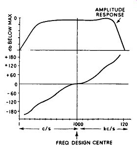
FIG. 2.5. Typical amplitude and phase characteristics of an audio amplifier.
The capacitive and inductive circuits employed in amplifiers can really disturb the application of feedback. So far we have assumed that the voltage fed back as negative feedback is exactly 180 deg. out of phase with the input voltage, and that the voltage fed back as positive feedback is exactly in phase with the input voltage. Unfortunately, these ideal conditions hold for only a comparatively small range of frequencies. Series capacitive reactances, such as coupling capacitors, cause a progressive phase advance, while leakage inductance in transformers and odd stray capacitances in the circuit promote a progressive phase delay. The phase change between the input and output signals occurs progressively, positively and negatively, with frequency either side of the frequency design center of the amplifier. The effect is illustrated graphically in Fig. 2.5.
Such phase change with frequency causes the feedback voltage to vary in phase in relation to the in put voltage either side of the optimum for the feedback employed. However, for negative feedback to change to positive feedback its phase must change through 180 deg. Whilst this is unlikely to happen within the range of the audio spectrum, it may take place at a frequency well above audio (supersonic frequency) or at a very low frequency. At these frequencies, the response of the amplifier is likely to have fallen to a comparatively low level, and this, of course, will result in the loop gain (AB) reducing in a similar ratio. The point is that for oscillation to commence, due to the change from negative to positive feedback, the factor AB must be unity or greater. In other words, to meet the conditions of stability, the product AB cannot be greater than I. Feedback design margins are employed to ensure this condition, the "phase margin" being defined as the angle by which the phase differs from 180 deg. at the frequency where the loop gain (AB) falls to unity. A margin of 30 deg. is usually aimed at, giving a maximum phase shift of 150 deg. The "gain margin", on the other hand, is defined as the amount by which the loop gain (AB) is below unity at the frequency where the phase shift is 180 deg.
A typical value for the gain margin is 10 db.
The application of positive feedback within a negative feedback loop, as already discussed, can play havoc with the stability margins, and extreme caution is needed when this form of feedback is applied. It sometimes pays to make the positive feedback somewhat frequency-selective so that it is applied in full force over one side of the spectrum only. Special attention can then be given in terms of stability to the circuit parameters concerned with phase shift at the frequency over which the feedback is applied.
When negative feedback is applied over more than two stages the possibility of instability is considerably increased. Very low-frequency oscillation may commence, causing the speaker cone to pump to and fro at one or two cycles per second. This effect may not be heard as such, though it can seriously degrade the reproduction. Similarly, very high-frequency oscillation is inaudible, but it can upset the operating condition of the output stage, causing the grid circuits to pass excessive current.
ADVANTAGES OF NEGATIVE FEEDBACK
Apart from reducing harmonic and intermodulation distortion to a very large degree, negative feedback also reduces spurious noises and signals, such as hum and microphony, in the same ratio as it reduces the gain. It also has a marked effect on the stability of the parameters of the amplifier due to random changes within the feedback loop. An example in this latter respect is an amplifier which without feedback has its overall gain reduced by some 10 percent as a result of a drop in mains voltage; the same amplifier with 20 db negative feedback has its gain reduced by only I percent, with the same drop in mains voltage. The reason is that the effect of gain changes is reduced by the feedback factor, which in the case cited is 10:1 (20 db). Negative feedback also considerably improves the overall frequency response of an amplifier. In this case, however, it is not true to say that the feedback improves the frequency response in the same ratio as it reduces the gain, as in the other cases mentioned. The reason is that when the response of the amplifier falls the frequency is well removed from the frequency design center of the amplifier, and at these frequencies the phase of the signal fed back differs somewhat from the ideal of 180 deg. The feedback is thus not 100 percent negative, though its phase may be well within the range required for stability.
An important function of feedback so far as hi-fi amplifiers are concerned is the effect it has on the anode impedance of the output valve. The application of feedback does not alter the optimum load of an output valve, as is some times thought, though it does alter the source impedance or the impedance as "seen" by the loudspeaker. The source impedance is decreased by the application of negative voltage feedback or positive current feedback, and increased by negative current feedback or positive voltage feedback.
We shall see later that a low source impedance is desirable from the point of damping the loudspeaker so as to avoid the cone oscillating to and fro after the application of a steep transient signal. For negative voltage feedback the source impedance (sometimes known as effective output impedance or resistance) is equal to ra . For current feedback ra is I+ AB multiplied by the feedback factor.
DAMPING FACTOR
The ratio of the nominal output impedance of an amplifier to the source impedance is known as the damping factor. A damping factor of 30 is typical for modem equipment. This would be due to the nominal 15 ohms output impedance divided by 0.5 ohm source impedance. Clearly, a low source impedance results in a high damping factor. A number of commercial amplifiers utilize a variable damping control so that the damping factor can be "optimized" to suit the speaker used. However, in practice it is found that little is to be gained by increasing the damping factor above about 20, particularly if a good-quality speaker is correctly loaded in an enclosure.
Nevertheless, some claim that all types of loudspeaker call for different damping factors, and that a variable means of achieving the critical damping is essential.
One should take into consideration the resistance of the speech coil, which is effectively in series with the damping circuit and represents the dominant impedance at high damping factors. For example, an amplifier having a damping factor in the region of 10 will have a net damping circuit impedance of some 13 ohms with a speaker whose speech coil measures 12 ohms. An increase in damping factor to 40 will reduce the damping circuit impedance by less than 1 ohm, bringing it down a little above 12 ohms.
The use of positive and negative feedback loops in the output stage, and a means of varying the positive feedback, allows the variation of the damping factor from about 30 to infinity. An infinite damping factor means that the source impedance falls to zero ohms; beyond this point the source impedance becomes negative, and if the negative output impedance is greater than the load impedance the amplifier commences to oscillate.
It must be stressed that negative feedback is not a cure for all amplifier ills; a poorly designed amplifier cannot be made into a high-quality one simply by applying or increasing the feedback. Indeed, as has already been intimated, increasing the feedback on an amplifier of dubious characteristics may well turn it into an oscillator, even if the feedback appears to be of negative mode.
The phase shift in the output transformer and coupling impedances, particularly in a not-too-costly output transformer, extends to high degrees at the limits of the audio band. This factor severely limits the amount of feed back which can be applied. There are one or two methods of reducing this phase shift which will be considered later.
Apart from instability, an amplifier of inherently high distortion will benefit but little by negative feedback. It may well happen that the order of the harmonic distortion may change by the application of feedback in a case such as this; for example, second and third harmonic distortion may be changed to fourth and ninth.
PROGRAM SELECTION AND EQUALIZING
The section of the hi-fi amplifier which deals with voltage amplification, program selection, the control of volume, loudness and tone, signal filtering and slope of filtering is known as the pre-amplifier, or control unit.
This section may be independent of the power amplifier and connected to it by means of a cable, as with the Pamphonic Type 2,001 amplifier, the Pye HF25/ A and many others, or it may be an integral part of the amplifier, as with the Pamphonic Model 1,004 and many smaller amplifiers of 10-watt rating.
Whether independent of or integral with the power amplifier, the function and general characteristics of the pre-amplifier are essentially unchanged.
With independent units, features in addition to the basic requirements are sometimes embodied, additional filtering, a slope control and extra equalizing positions being typical in this respect. Hi-fi outfits comprising separate units are invariably more expensive than their composite counterparts. More scope can thus be given to the designer to facilitate the development of his pet feature; more money is available for the extra components needed and there is more room available on the chassis since size is not restricted as is the case with some composite units.
Most pre-amplifiers are designed to cater for four program sources, namely, pick-up (gram), radio, tape, and microphone. The program required is selected by a rotary switch (selector switch) and the signal eventually finds its way to the control grid of the voltage-amplifier valve.
There are four input sockets, of course, corresponding to the channels available, and the signals can be present on each of the four sockets ready for immediate selection when required. To avoid a strong signal on a channel which is not selected from breaking through along with the signal on the selected channel, the sockets corresponding to the channels not in use are sometimes short-circuited by means of an additional wafer switch ganged to the selector switch. The Pye HF25 has such a feature.
In addition to the four program positions, the selector switch may also have three or four positions relating to the pick-up channel, giving six or seven positions in all. The extra positions on the pick-up channel permit the selection of the most suitable equalization characteristic for the record being played.
Unfortunately, over the years, records have been cut with a diversity of recording characteristics, each demanding a slightly or greatly modified equalization characteristic. However, since the universal acceptance of the R.I.A.A. (Radio Industries Association of America) recording characteristic--known in Britain as British Standard No. 1928--there will soon be little need for complex switched equalizing circuits. The bulk of the long playing repertoire in future years will have been recorded to this characteristic. For the present, three or four degrees of equalization are desirable to cater for disks which have already been cut to suit one or other of the re-play curves given in Fig. 2.6.
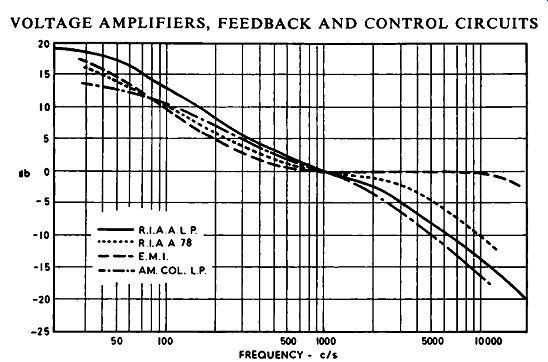
FIG. 2.6. Equalization curves in current use.
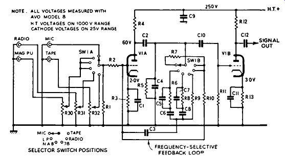
FIG. 2.7. The first-stage circuit of the Pamphonic Model 2,001 amplifier.
For reasons closely related to the design of pick-ups and signal-to-noise ratio on re-play, disks are cut with a rising high-frequency response and a falling bass, the opposite to the curves in Fig. 2.6. The reasons for this are given in a later section. Clearly, in order to secure a straight-line frequency response, equalization curves must be the opposite of the record curves.
PRE-AMPLIFIER FIRST STAGE
Let us now investigate a circuit providing the functions so far outlined.
In Fig. 2.7 is given the first-stage circuit of the Pamphonic Model 2,001. In this, the circuit arrangement associated with the selector switch clearly follows the lines laid down in this section. The signal, after selection by SWIA, is applied to the grid of VIA by way of R2 (valve V1 being of the double-triode variety, Mullard ECC83). Pre-set controls are available on the pick-up, radio and tape channels so that the signal level can be pre-adjusted to avoid overloading the first stage where the program-source signal is of high level.
The amplified signal appearing across R4 is coupled capacitively to the grid V1B through C2 and C10. A portion of the signal appearing across R4 is also fed back to the grid of V1A by way of the switched resistor and capacitor networks. This results in selective attenuation due to negative feedback and thus provides various degrees of equalization as selected by switch SW 1B, which is ganged to the selector switch SW I A. Bass correction is controlled by capacitors C6 and CS (bass boost) with a very low-frequency roll-off, due to the progressive reduction in feedback at the lower frequencies. Capacitors C2 and C3 are concerned essentially with the coupling of the loop and have little material effect on the response, being of high value--32 and 50 mF respectively. Capacitors CS and C7, along with their associated resistors, control the top-cut. A certain degree of fixed correction is also given by RS and C4.
The arrangement does not apply any appreciable amount of negative feedback to the program circuits, owing to the isolating resistor R2, and it represents one of the most popular equalizing circuits in hi-fi use today.
It is extremely quiet, stable and efficient in that the unwanted gain is employed as a distortion-reducing agent.
On the "mic", "tape" and "radio" positions, the feedback is not frequency-selective, being controlled by resistors R7 and R10 respectively.
Since high gain is required on the microphone channel relative to the other channels, the feedback is considerably reduced by R7 being of much greater value than R10, and by R7 and R10 being in series when the selector switch is set to "mic". Thus, apart from providing equalization, the negative feedback can be switched to facilitate a balanced output in spite of the various voltages on the four channels.
The equalized signal is further amplified by VIB, and appears in this form across the load resistor R12. From here it is conveyed through C12 to the following section of the pre--amplifier circuit, which is usually the tone control section.
The circuit in Fig. 2.7 is designed to match or load most magnetic pick-ups of the hi-fi type. It must be stressed that every pick-up, irrespective of type, has an optimum load which provides the correct curve to work into the equalizing network as stipulated by the makers. With magnetic pick-ups, a load larger than the optimum results in an increase in high-frequency output, while an increase in low-frequency output occurs with crystal pick-ups.
The practice of incorporating facilities for correct impedance-matching of various pick-ups is increasing in popularity among amplifier manufacturers. The Armstrong and R.C.A. units adopt two input sockets, one for magnetic pick-ups and the other for crystal types, which can be switched independently. The Pye Mozart, on the other hand, features two controls (pre-set), one for providing attenuation and the other for matching. This is known as "Dialomatic Pick-up Compensation", and permits immediate matching for any pick-up. A list of settings for a very wide range of pick-ups is given in the instruction manual. A similar idea is used on the Decca FFR25.
Other manufacturers use plug-in matching units.
Some simple equalizing networks rely on the fact that the response of the pick-up is altered with alteration in load resistor.
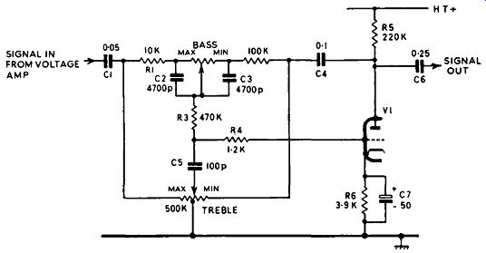
FIG. 2.8. Baxandall tone-control circuit, with typical component values.
TONE CONTROL
The most popular tone-control system, giving independent control of both bass and treble, is that due to P. J. Baxandall ( Wireless World, October, 1952). The circuit of the network is given in Fig. 2.8, from which will be seen that it is focused around the triode valve V1, this usually being one half of a double-triode. Basically, the operation of the circuit relies upon frequency selective negative feedback, the feedback loop being by way of the anode of the valve, through C4 and the resistor/capacitor network, and back to the grid circuit through R4.
The overall control is formed by the amalgamation of two somewhat complex independent treble and bass control circuits. In order to secure both treble lift and treble cut, the treble control has a tapped resistive element connected to chassis. The treble-lift elements are C5 and the section of the treble control connected across chassis and the junction of C1, R1, while the treble-cut elements are C5 and the section of the treble control connected across chassis and the junction of R2, C4. Bass lift and cut is given by the bass control in association with C2, C3, R1, R2, R3 and back to the grid by way of R4.
The lift and cut is confined to each end of the audio spectrum, thus permitting extreme frequencies to be lifted and cut to a large degree without disturbing the response at the center of the spectrum.
There are a diversity of tone-control circuits which rely simply on filtering the signal to varying degrees to provide the necessary boost or cut either side of the spectrum. Such an arrangement is sometimes called a "passive tone control". Two simple resistor-capacitor networks of this kind are shown in Fig. 2.9; circuit (a) providing treble control and circuit (b) bass control. A combined treble- and bass-control circuit is also a fairly common set-up, and one which in some quarters is held in favor over the feedback arrangement, possibly owing to the greater flexibility of response over a wider frequency range.
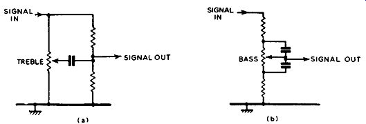
Fig. 2.9. Two simple resistor-capacitor passive tone-control circuits:
(a) providing control of treble and (b) control of bass.
Passive networks can be inserted between two voltage amplifiers since, in common with all tone controls and equalizers, inevitable attenuation results from the circuit, and this must be made good by additional amplification. Generally speaking, it is not a good idea to include the network in a low-level stage, such as in the input circuit of the first voltage amplifier, for the reason given above. This may not apply, however, to pick-up equalizers if the pick-up used has a large output voltage.
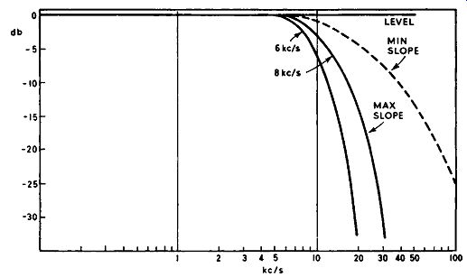
Fig. 2.10. Two-position filter characteristic with a slope control.
After suitable amplification by the valve following the tone-control network, the signal is usually fed into a filter system.
FILTERS
A filter is included to avoid the amplification of noise due to worn records and whistles caused by inter-channel interference when the hi-fi equipment is used with an A.M. radio tuner. Since the noise and interference frequencies are focused towards the high-frequency end of the audio spectrum, the filter is arranged to have a steep treble cut.
Most pre-amplifiers have a four-position filter switch, giving three positions of treble cut at 4 khz, 7 khz and 12 khz, and a "filter out" position.
In addition, a control designated "slope" is often incorporated whose purpose is to vary the rate of treble attenuation from a minimum of some 8 db per octave to a maximum approaching 35 db per octave. The idea is shown graphically in Fig. 2.10. Here two filter positions are available, one at 6 khz and the other at 8 khz. The broken-line curve shows how the slope control serves to affect the rate of attenuation. Maximum slope indicates maximum attenuation rate.
When using new disks of recent pressing, it is desirable to commence operation with the filter switched out of circuit and with the bass and treble controls at "level", thus giving an extended flat response. Then, as governed by the acoustical environment, the bass and treble controls should be adjusted, bearing in mind that the ear is the final arbiter, as distinct from numbers on a dial!

(Left) FIG. 2. 11. Capacitive-inductive low-pass filter. (Right) FIG.
2.12. Each coupling section provides a low-frequency roll-off at the
rate of 6 db per octave; 18 db are given by the three cascaded couplings
shown.
With worn records, the overall performance can be enhanced with the filter adjusted to give a cut-off at 4 khz or 7 khz coupled with the application of a little top-boost by the treble control. The same reasoning usually applies to noisy radio programs. With music of a high transient content, it often pays, if a filter position is called for, to reduce the rate of attenuation by the slope control. This avoids "overhang" and "ringing" at high frequencies.
Filters come in two types. First, there is the tuned inductor arrangement in which an inductor connected in series with the signal source is resonated by capacitors. This is illustrated in Fig. 2.11. The circuit is tuned so that a sharp dip occurs at the high-frequency end of the response, and the falling side of the curve represents the treble-cut effect. At resonance, the circuit offers a very high impedance to signals at that frequency. The capacitors are usually switched, thus providing various filter frequencies, while the control of slope is by damping the circuit with the resistor. A variable resistive element permits a variable control of slope, as already explained.
Secondly, there is what is known as the "parallel T" circuit. This requires a large number of low-tolerance resistors and capacitors in order to give the desired high rate of attenuation at the various filter frequencies. Such a network is used in the R.C.A. pre-amplifier.
Combination circuits are also used, as also are less elaborate resistance / capacitance networks in pi and M-derived configurations. It should be noted that resistance/capacitance inter-stage couplings affect the frequency response, but at the low-frequency end. A sharp cut at a low frequency is often desirable for eliminating gram motor rumble, and for avoiding unnecessary low-frequency distortion, particularly where the program material possesses excessive low-frequency signal and the amplifier is not too good at the low-frequency end of the spectrum. It is far better to cut off sharply at about 40 hz and achieve a "clean" bass than endeavoring to extend the response down to about 20 hz and create unnecessary distortion.
Rumble filters, as these devices are often called, are switched on some units, giving only the positions "filter on" and "filter off". They are usually simple in design, often being built into an inter-stage coupling. A single resistor/capacitor coupling gives a roll-off of 6 db per octave. Since this is hardly steep enough for the purpose in hand, however, cascaded couplings are favored. As each coupling gives the standard 6 db per octave roll-off, a slope of 18 db per octave is achieved by the use of three networks in cascade (Fig. 2.12). The signal leaving the filter may be taken direct to the output socket of the pre-amplifier unit, or to another valve for further amplification and to facilitate matching to the power amplifier.
PRE-AMPLIFIER FINAL STAGE
A triode valve connected as a cathode follower is favored as the final stage in the pre-amplifier unit. The advantage of the cathode-follower in this application is the low impedance across which the output signal is developed.
This allows relatively long pre-amplifier /power amplifier connecting cables without causing undue attenuation of the higher audio frequencies, whilst also minimizing the pick-up of spurious signals, such as mains hum.
A cathode-follower stage is shown in Fig. 2.13. It will be seen that the load impedance is connected between cathode and chassis instead of between anode and h.t. positive, as in the more conventional arrangement. The cathode loading feature results in 100 percent negative feedback, and as a consequence the distortion developed by the stage is at extremely low level, as also is the gain, being less than unity. This is of little moment, however, since adequate signal is usually available at the output of the filter, and the stage serves admirably as a matching device, for apart from its low output impedance, it has a very high input impedance and thus has little shunting effect on the circuit to which it is connected.
In the circuit in Fig. 2.13, R_g is the normal grid resistor, C the coupling capacitor, R1 the load and Rk the ordinary cathode-bias resistor.
The pre-amplifier volume control is invariably connected between the output signal at the filter and the cathode-follower valve grid.
There is still considerable controversy regarding the merits and demerits of the loudness control. It seems to be an accepted feature in the United States, though in Britain its use is by no means universal. It is not a new device, having been used many years ago in the form of a tone-compensated volume control in broad cast receivers.
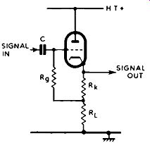
FIG. 2.13. The cathode-follower. The stage gain is negative, being less
than unity.
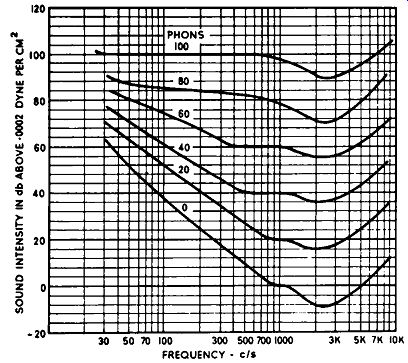
Fig. 2.14. Fletcher Munson equal loudness curves show how the ear's
response varies with intensity.
It will be recalled from Section 1 that the ear does not respond in the same way to all frequencies. How the ear responds over the audio spectrum is revealed by the Fletcher-Munson equal loudness curves (Fig. 2.14). These curves show the required relative levels of sound at various frequencies for a sensation of equal loudness, being based on the reference frequency of 1,000 hz. It will be recalled that the loudness of sound in phons is numerically equal to the sound intensity in decibels of an equally loud 1,000 hz note, and that zero phon (corresponding to zero db at 1,000 hz) is equal to a sound pressure of 0.0002 dyne per square centimeter (this, incidentally, is equal to 10·1s watts per square centimeter). The curves demonstrate clearly that at low-level listening a considerable bass lift, and to a lesser degree top lift, is demanded in order to secure the sensation of the same apparent loudness over the full frequency range. There is little doubt that reproduction at a level of some 5 watts, with the treble and bass control adjusted to suit the room conditions, is of a far superior quality to that at 500 milliwatts with the tone controls left at their original settings--this condition can be created simply by backing-off the ordinary volume control. To secure anything like the original balance, considerable bass lift and a small amount of top lift is essential.
To avoid having to make these tone-compensating adjustments every time the volume control is adjusted, the loudness control has been evolved, and is designed around the Fletcher-Munson curves to quite a high degree of accuracy, at least from the low-frequency point of view. Retarding the control provides automatically the required degree of bass lift.
Two loudness-control circuits are given in Figs. 2.15 and 2.16. The first is arranged around a tapped volume control to which are connected capacitive elements. With the control in the maximum position the capacitive reactance shunting is at minimum, but as the control is rotated towards the minimum position the shunting increases progressively and the higher frequency components of the signal are attenuated with respect to the low frequencies, which effectively provides a bass lift. The cross-over point is somewhat governed by the resistance R. The negative-feedback scheme in Fig. 2.16 makes use of an ordinary volume control and a frequency-selective negative-feedback loop by way of capacitor C. The loudness control and resistor R form a potential-divider in the feedback circuit, feedback being at maximum at the minimum position on the loudness control. Thus, as before, when the loudness control is retarded towards minimum the feedback of the higher audio frequencies increases, and a progressive boost of bass results.
It is usual to employ an ordinary volume control as well as a loudness control, the two controls often being connected in cascade, though in some cases they may be independently positioned in different stage couplings.
Their actions are somewhat related, and for this reason their settings should be established with some care so as to avoid over-emphasis of the bass, possibly falling outside the range of the bass control proper.
The following procedure should be adopted where possible: turn the loudness control to maximum, or switch it out of circuit completely if a switch is provided for this purpose; set the volume control to a fairly high level; balance the sound to suit the room acoustics by means of the bass and treble controls; reduce volume to normal room level by backing-off the loudness control. A reasonable balance should be maintained throughout the range of the loudness control over ordinary volume levels if this process is followed. Severe bass distortion will result, however, if the loudness control is turned to minimum, and the room-level volume adjusted solely by the volume control.
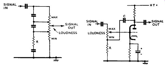
(Left) FIG. 2.15. Loudness control formed by tapped frequency-selective
volume control. (Right) FIG. 2.16. Negative-feedback loudness control.
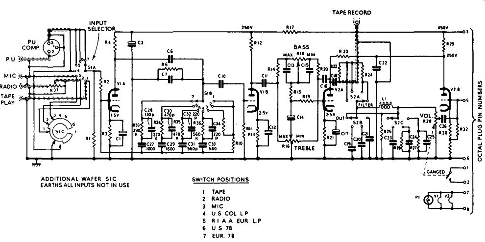
FIG. 2.17. Complete circuit of the Pye HF25A pre-amplifier. To ensure
accurate voltage reading a high-resistance voltmeter (more than 10,000
ohms per volt) must be used.
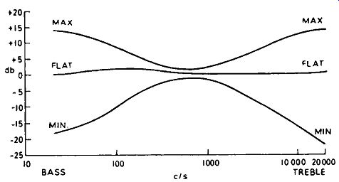
FIG. 2.18. Tone-control characteristics of the Pye HF25A pre-amplifier.
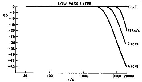
Fig. 2.19. Filter characteristics of the Pye HF25A pre-amplifier.
PRE-AMPLIFIER COMPLETE CIRCUIT
Fig. 2.17 is a complete circuit of the Pye HF25A pre-amplifier, and it will be instructive to look at the various sections in the light of our previous discussion. The required signal source is selected by switch SIA and applied to the grid of the first voltage-amplifier valve V1A. The unused program sources are short-circuited by switch section S 1 C to avoid breakthrough, and a variable attenuator is included in the radio channel input so that any high level signal on this channel can be suitably reduced to prevent overloading of the first valve.
The input selector switch is ganged to the equalizer switch SIB and four positions of equalizing are available on the pick-up channel on settings 4, 5, 6 and 7, negative feedback being used for this purpose and for controlling the gain over the four input channels. The equalized signal is further amplified by V 1 B, and control of bass and treble is secured by reason of the Baxandall negative-feedback system in conjunction with valve V2A. The signal is then passed into a three-position filter circuit, giving a sharp treble cut at 4 khz, 7 khz and 12 khz. The filter is adjusted by switches S2A, S2B and S2C, which also give a "filter out" position. The filter is of the inductive-capacitive type, with L1 as the inductive element.
The signal at the output of the filter, at the rotor of S2C, is passed through the volume control and on to the final valve V2B, which is arranged as a cathode follower. The signal is finally conveyed across R31 to pin 5 on the octal output plug.
A handy feature, and one which is found on many control units, is the "tape record" output socket. At this point appears the amplified signal voltage exclusive of filter influence. This can be used for feeding another amplifier, if required, or used as an input signal for a tape recorder. Both h.t. and l.t. for the unit is derived from the main power amplifier, which is the subject of the next section.
Tone control and filter characteristics of the unit are given in Figs. 2.18 and 2.19 respectively.
To summarize, the pre-amplifier serves to match into the various signal sources so as to secure maximum signal transfer and signal-to-noise ratio, to equalize for the shortcomings of the program material, to provide control of volume (sometimes loudness) and tone, and to raise the low-level pro gram signals to a level of about I ·5 volts for application to the power amplifier. To do this the pre-amplifier invariably requires an overall gain of some 60db.