ELECTRICAL power measured in watts (W) is the product of the voltage (E) and current (/), that is, W = E x I. Thus, for a constant power we can either increase the voltage and decrease the current or decrease the voltage and increase the current. At the output of a pre-amplifier we have in relation to the very small signal current a rather high voltage-because at the pre-amplifier stage we are mainly concerned in obtaining voltage amplification. However, at the output of the power amplifier we need to produce a larger current, since this is what is wanted by the loudspeaker. In fact, a signal current of 1 amp. is required to flow through a 15-ohm speaker to represent a power of 15 watts. This means that 15 volts would be measured across the speaker at this power. This is considerably different from the few millionths of an amp. of signal current which is present in the final load of the pre-amplifier.
The valve is inherently a high-resistance device, which means that the signal current in the anode circuit is limited to a few thousandths of an amp., though, in order to secure this condition, the voltage for a given power is relatively high. Clearly, a means is necessary for transforming this high signal voltage and low current so that the current is considerably increased and the voltage proportionately decreased for presentation to the loudspeaker. This transforming process is achieved quite easily by the use of a transformer-in this application it is termed the "output transformer". The winding connected to the anode circuit of the valve, across which is developed the high signal voltage, is known as the primary winding, and is composed of a large number of turns of fine wire since it is required to pass only a small current. The winding connected to the speaker, through which is passed the high signal current, is known as the secondary winding, and is formed of only a few turns of heavy-gauge wire. The arrangement is represented in Fig. 3.1.
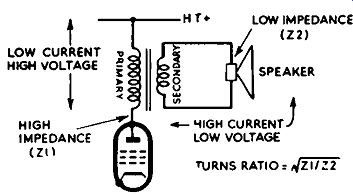
FIG. 3.1. Matching the speaker to the output stage is an important consideration
in hi-fi practice.
A transformer devoid of losses has a voltage ratio equal to the turns ratio, that is,
Voltage across primary: Voltage across secondary = Primary turns: Secondary turns. Thus, a transformer with a 10:1 turns ratio will have 10 volts induced across the secondary when a signal of 100 volts is applied across the primary. The current will be transformed in the same ratio, assuming ideal conditions.
Across the secondary winding of the transformer (Fig. 3.1) is connected the resistance or impedance (impedance is the term used when we are dealing with alternating quantities) of the loudspeaker. This impedance--let us call it 22--is reflected across the primary winding, but is altered in magnitude according to the expression (Z~) 2 x 22, where NI is the number of turns forming the primary winding, and N2 the number of turns forming the secondary winding.
Thus, if the transformer has a turns ratio of 10:1 (step-up from secondary to primary), the factor z~ resolves to 10, the square of which is 100. Now, if the impedance of the loudspeaker (22) is equal to 10 ohms, then the impedance reflected across the primary is 100 x 10=1,000. This is the impedance as "seen" by the valve. It is rather important to get these facts clear, as they have a direct bearing on the performance of the power amplifier.
The transformer, therefore, apart from altering the voltage and current transfer, also serves as an impedance-matching device. In the case cited, the transformer of ratio 10:1 has transformed the 10-ohm loudspeaker impedance to 1,000 ohms. Impedance-matching in the output stage is an extremely important consideration, for unless the impedance of the loudspeaker is transformed to match exactly the optimum working impedance of the valve or valves, the loudspeaker will not receive the full available power.
Re-arranging the expression given above, we can discover the turns ratio required to match the speaker impedance 22 to the high impedance:
Most power amplifiers have switching or plug-and-socket facilities available for adjusting the output impedance of the amplifier to suit a wide-range of speaker impedances. As the fraction of voltage fed back as feedback is affected by impedance adjustments, it is desirable to alter the value of the feedback resistor (and sometimes the capacitor) when the output impedance is changed. Commercial amplifiers have indicated in their instruction books the value of components required for the various output impedances. Where a positive-feedback loop is incorporated, this also requires adjustment when changing impedance.
A power amplifier should never be operated with the speaker removed unless a resistor of equal value to the speaker impedance is used instead. An unloaded amplifier will develop very high audio peak voltages across the primary of the output transformer, and these can quickly destroy the transformer insulation.
OUTPUT TRANSFORMER
In practice, there is no such thing as a perfect transformer, since losses occur in both the primary and secondary windings and in the core itself.
The inductance of the primary governs the relative amplification at low audio frequencies, while leakage inductance in both windings results in a loss of high audio-frequency response. These losses also promote phase shift at the low- and high-frequency sides of the audio spectrum, and sometimes make it difficult to maintain a reasonably high degree of negative feedback without instability.
The windings also possess distributed capacitance, and due to this there is invariably a peak in the response curve at the frequency at which the equivalent leakage reactance resonates with the Jumped equivalent capacitance.
In transformers designed for hi-fi work, all these losses are kept at the absolute minimum, resonances are damped and arranged to fall outside the audio spectrum, considerable iron is used for the core so as to maintain adequate low-frequency response, and distributed capacitances are minimized by dividing the windings into sub-sections, as shown in Fig. 3.2. This specialized design is inevitably reflected in the cost of the item, and is the reason why the output transformer is invariably ... There is much truth in the saying that an amplifier is only as good as its output transformer.
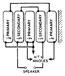
FIG. 3.2. Distributed capacitances in the output transformer are minimized
by dividing the windings into sub-sections, as illustrated.
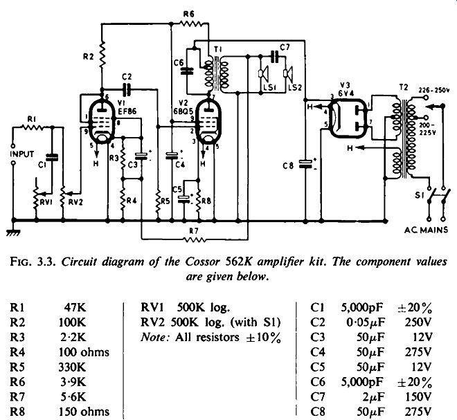
FIG. 3.3. Circuit diagram of the Cossor 562K amplifier kit. The component
values are given below.
Hi-fi transformers need to be bulky devices in terms of iron in order to permit the full rated power of the amplifier to be handled down to about 30-hz, and to avoid harmonic distortion due to core saturation. The core material affects the primary inductance, which needs to be relatively high for an adequate low-frequency response for the smallest possible amount of wire.
Both the cross-sectional area of the core material and its permeability are governing factors on the inductance; increasing either of them results in an increase in inductance.
In recent years a core material having a higher permeability value than the conventional "Stalloy" laminations has been under development. This is a cold-rolled silicon steel, having grain-orientation properties, which is known as "Unisil". For a stated low-frequency performance, a transformer with this new core material is approximately half the weight of a transformer using the older grades of core material. The well-known "C-core" is the result of further developments along these lines and, although somewhat more expensive than "Stalloy" laminations, permits even further reduction in both weight and size.
SINGLE-ENDED OUTPUT STAGE
To illustrate the single-ended output stage, the circuit diagram of the Cossor Amplifier Kit 562K is given in Fig. 3.3. This is an ideal kit, easily made up by the non-technical experimenter, with which to study the rudiments of sound reproduction. It is not claimed to possess hi-fi quality, but in spite of its basic simplicity, the performance may pleasantly surprise even one having long association with hi-fi equipment, especially if used with a first class loudspeaker.
The first valve, V1, serves as the voltage amplifier, the signal being applied to the control grid by way of the volume control RV2, after correction by the tone control RV1. The signal in amplified form is developed across R2, and from here fed to the control grid of the output valve, V2, through the coupling capacitor C2. The output valve is biased in the ordinary way by the cathode resistor R8. The volts drop across this resistor due to the current in the valve causes the cathode to rise positively with respect to chassis. Because the control grid of V2 is in d.c. connection with the chassis through the grid resistor R5, the grid is effectively more negative than the cathode and is thus biased, the magnitude of the bias being equal to the volts drop across the cathode resistor R8.
This is the normal function of so-called cathode bias, which is used extensively in radio and television receivers as well as audio equipment.
The valve is biased to class "A" conditions. This means that in the normal condition of operation the anode current is not cut-off for any portion of the cycle of signal applied at the control grid.
The signal in the anode circuit is conveyed to the loudspeakers, LS1 and LS2, by way of the output transformer T1, impedance matching being achieved in the way already described. The tapping on the primary winding of T1 may require explanation. The portion of the winding across which the signal voltage is developed is that across the capacitor C6. The section between the tap and R6 serves as a hum-neutralizing device, h.t. from the cathode of the rectifier valve V3 being applied to VI through the upper part of the primary and R6. Thus, this part of the primary can, in effect, be considered as a smoothing choke with the added filtering contributed by R6, in association with the reservoir capacitor C8 and smoothing capacitor C4.
Negative-voltage feedback is applied over the two stages from the secondary of the output transformer through R7 to the cathode circuit of V1. The feedback loop is completed from the other side of the secondary winding to chassis. This is one of the most popular ways of applying negative feedback. (Of course, if the feedback and chassis connections on the secondary winding are reversed, the feedback becomes positive and the amplifier turns into an oscillator. Such a mis-connection could occur in changing an output transformer of this kind.) It will be seen that two loudspeakers are used. The one connected directly across the secondary deals with the lower and middle audio frequencies; the one connected by way of C7 handles the higher frequencies, and is often referred to as a .. tweeter" or high-frequency reproducer. It is some what isolated from the lower audio frequencies owing to the high reactance presented by C7 to these signals. In effect, the arrangement can be considered as a simple cross-over filter, and will be dealt with in more detail in a later section.
PENTODE OR TRIODE
In the early days of hi-fi, the triode was invariably held in favor over the pentode ( or tetrode) owing to its smaller distortion figure and lower anode impedance as compared with the pentode. For example, at maximum output a power triode in a single-ended circuit may produce something like 5 percent distortion, mainly second harmonic.
The distortion due to a power pentode operating similarly, however, may rise to some 13 percent, made up basically of third harmonic and higher order harmonics. The reason for such a high distortion figure is the result of the S-shaped grid voltage/anode current characteristic curve of the pentode.
This characteristic is shown in Fig. 3.4, and the general picture is completed by a sine wave corresponding to the signal applied at the control grid, the valve being biased to class A, and the resulting signal across the anode load.
It will be seen that the bends at the top and bottom of the curve cause a certain flattening of the peaks of the amplified signal, which promotes a spurious third-harmonic signal. An analysis of the distorted signal would reveal that it is composed of the fundamental component plus a smaller third-harmonic component and higher order harmonics.
Fig. 3.5 shows that the grid voltage/anode current characteristic curve of the triode is considerably more linear than that of the pentode.
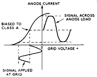
FIG. 3.4. The S-shaped characteristic curve of the power pentode results
in the production of third-harmonic distortion, shown by the flattening
of the peaks of the output signal.
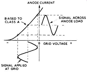
FIG. 3.5. The triode has a more linear curve, and the resulting distortion
is essentially second-harmonic.
There is a slight inward bend, however, and this results in slightly greater amplification of one half cycle of the signal than the other.
This is representative of second harmonic distortion. The triode, on the other hand, is less sensitive AT GRID than the pentode, requiring a greater input signal for a given output power. However, if the drive is exceeded the distortion rises rapidly, and can be very disconcerting if this happens on program peaks in a poorly designed amplifier, or if the amplifier is insufficiently large for the purpose in hand.
A greater overload margin is available with the pentode, and to a smaller degree with the tetrode, owing to the "cushion" effect created by the gradual bends at the ends of the curve. Unfortunately, the application of negative feedback tends to neutralize this desirable effect, and the valves behave more like triodes with regard to accidental overload.
In order to prevent power being wasted in the output valve, the load impedance should theoretically match the anode impedance of the valve. In practice, this does not always follow because the load for maximum power does not coincide with that for minimum distortion. There is, therefore, an "optimum load" value which gives a compromise between the two conflicting factors.
Fig. 3.6 shows curves for power output and percentage distortion against anode-load impedance, and these clearly reveal the need for an impedance compromise. If maximum power output is aimed at, then both second- and third-harmonic distortion will be at a high level. If the load is decreased to 4,000 ohms, third-harmonic distortion is Jess troublesome but second-harmonic rises, accompanied by a power decrease. Generally speaking, second-harmonic distortion is Jess disturbing than third-harmonic and, as we shall see later, can be eliminated in a push-pull output stage. Thus, it is desirable to work to the best compromise between third-harmonic distortion and power output. Neither the technician nor the enthusiast need worry about working out optimum loads, since this has already been done by the valve maker, and the figures can readily be obtained by referring to the data supplied with the valve.
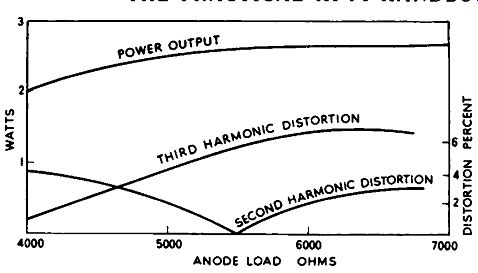
FIG. 3.6. Curves, related to a pentode output valve, for power output
and distortion plotted against anode-load impedance.
Similar curves for a triode power valve are given in Fig. 3.7. Here there is only second-harmonic distortion to deal with, and it is desirable to use a large-value load if minimum distortion is required.
Account must be taken of the fact that in practice the impedance presented to the output valve changes considerably over the operating frequency range owing to the varying impedance of the loudspeaker. More over, as the load is not a pure resistance, but possesses a reactive component, the task of finding the best load compromise is made somewhat more difficult.
PUSH-PULL OUTPUT
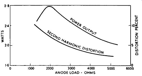
FIG. 3.7. Curves, related to a triode output valve, for power output
and distortion plotted against anode-load impedance.
The push-pull output stage is usually a feature of hi-fi amplifiers, and the basic circuit is shown in Fig. 3.8. The signal is applied to the two valves in a way that when the control grid of one is swung positive the grid of the other is swung negative, and vice versa. The anode current is thus rising in one valve while it is falling in the other; hence the term "push-pull". The signal is applied in relation to a fixed "zero signal" point, such as chassis, either from a transformer with a tapped secondary winding or from a phase-splitting valve. In this way, not only is the power output increased but, more important from the hi-fi aspect, all second and even harmonic distortion is automatically cancelled. Thus, a properly designed and adjusted push-pull stage should produce virtually zero second-harmonic distortion. Third and odd harmonic distortion will still be present, of course, but this can be reduced to a very low figure by the application of negative feedback. Even without feedback, a triode push-pull stage will exhibit a very low distortion figure, bearing in mind that second harmonic is the prominent factor in each valve, and will be eliminated in a push-pull stage. This is one of the reasons why triodes used to be very popular a few years ago, before negative feedback was fully developed.
In hi-fi application, the output valves are arranged to operate in class A, though this is by no means a necessity, for if greater power is called for, and an increase in distortion is permissible, then the valves may be biased towards
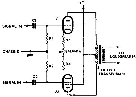
Fig. 3.8. Basic circuit of push-pull output stage using tetrode valves.
anode-current cut-off and the signal may be increased to push the valves into grid current on the positive half-cycles. In this way a very much larger signal swing occurs in the anode load, and the output power is correspondingly increased. This scheme is used extensively in public-address and sound reinforcement amplifiers, where quantity rather than quality is demanded.
In most hi-fi power amplifiers the output valves are biased by reason of the volts drop across their cathode resistors (R3 and R4 in Fig. 3.8). The variable potentiometer serves to adjust the two valves for d.c. balance.
In other amplifiers, particularly those whose operating conditions deviate from pure class A, a separate bias line is used, sometimes derived from a separate bias power unit.

FIG. 3.9. Phase-splitting (a) by means of a center-tapped transformer,
and (b) by means of a simple transformer and resistive divider.
The simplest method of providing two input signals 180 deg. out of phase for a push-pull stage is by means of the center-tapped transformer (Fig. 3.9a). An alternative arrangement, which uses a simple coupling transformer, is shown in Fig. 3.9b. In both cases the secondary of the trans former provides two equal anti-phase signals. In the latter case, however, a zero-signal reference point is obtained at the junction of the resistive divider (R1 and R2). If required, the transformer can give a signal step-up to the push-pull valves and, as with the output transformer, it will also serve to match the anode circuit of the driver valve to the grid circuits of the push pull valves.
In arrangements which deviate from true class A working, the secondary of the transformer is usually placed in the grid circuits of the output valves.
The reason for this is to provide a relatively low d.c. resistance in the grid circuits as a means of avoiding severe overload distortion when the output valves are driven into grid current. Transformer phase-splitting is thus usually confined to large public-address and sound-reinforcement amplifiers.
Since a transformer inevitably introduces some degree of distortion, transformer phase-splitting is rarely if ever used in hi-fi amplifiers. Instead, a method of phase-splitting by means of a valve arrangement is always favored.
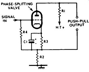
FIG. 3.10. Circuit diagram of the simple "split-load" phase-splitter
stage. The gain of this circuit is less than unity.
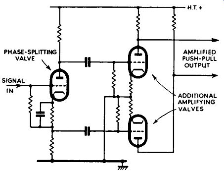
Fro. 3.11. In order to obtain sufficient drive signal for the push-pull
power valves, additional amplifying valves may be necessary, as shown.
A very popular valve phase splitter circuit is shown in Fig. 3.10.
In this circuit, which is designed around a triode or a pentode strapped as a triode, the load resistance is split; half of it is connected in the anode circuit (R1) and the other half in the cathode circuit (R2). The input signal from the voltage amplifier is applied between the grid and chassis, and due to the high-value load (R2) in the cathode the resulting large amount of negative feedback gives rise to considerable loss of gain over an ordinary voltage amplifier, in which the net load is in the anode circuit.
In fact, the actual gain between the grid and either side of the push-pull output is around 0.9, giving a total gain between the two output terminals of 1.8. The voltage output at either terminal is half that of a comparable voltage amplifier, which means that if a fairly high drive is required by the push-pull output valves additional amplifying valves have to be introduced between either output terminal and the grids of the output valves (Fig. 3.11). This arrangement will be found in some modern equipment.
The phase-splitting valve is biased by the usual cathode resistor (R3 in Fig. 3.10) and the grid-return resistor, R4, being connected to the junction of the cathode load and the biasing resistor. The heater of the valve is some times connected to a positive potential so that it approaches that of the cathode. The reason for this is to reduce hum which may otherwise be reflected from the cathode circuit into the grid circuit.
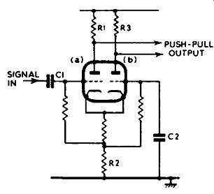
Fig. 3.12. Circuit diagram of a cathode coupled phase-splitter stage.
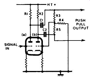
FIG. 3.13. Circuit diagram of a floating paraphase inverter stage.
Fig. 3.12 shows the circuit of a cathode-coupled inverter, used in the Pamphonic Model 2,001. As with a number of modern phase-splitting circuits, it calls for the use of two triode valves, a double-triode unit being admirably suited to the function. Section (a) of the valve serves as an ordinary earthed-cathode amplifier, in which the input signal is applied through C1 and delivered across R1. Section (b) receives its signal by way of C2 from that present across the common cathode resistor R2, and delivers its output across R3. Section (b), in effect, is an earthed-grid amplifier, whose output signal is exactly 180 deg. out of phase with the signal at the output of section (a). The so-called paraphase circuit is also used in various forms for phase splitting. The version given in Fig. 3.13 is sometimes called the "floating paraphase", in which two triodes (a double-triode valve) are used. The signal applied to triode (a) grid is developed in amplified form across R1 and applied through C1 to one of the push-pull valves. Resistors R3 and R4 in series also form a load on triode (a), and the signal voltage at their junction is applied to the grid of triode (b). Triode (b) thus gives rise to an amplified anti-phase signal across its load R2, which is conveyed by way of C2 to the grid of the other push-pull output valve. Resistors RS and R4 in series also form a load on triode (b). The circuit is maintained in a good state of balance since opposing voltages are developed across R4 due to the two triode sections, and the signal voltage applied to the grid of triode (b) is maintained at just the right level for optimum balance. In effect, the circuit has a self balancing action.
There are many variants of the phase-splitting arrangements mentioned, but the information given should be sufficient to assist the technician and enthusiast with any servicing and adjustments which may be required in this section of the amplifier.

Fig. 3.14. Frequency response characteristic of the Pye Provost amplifier.
To summarize, the requirements of the phase-splitting stage, sometimes known as inverter stage, are to provide a balanced drive signal for the push pull output valves from a common signal source, such as a voltage amplifier; to provide a signal of sufficient voltage, without distortion, to ensure maximum output of the power amplifier; and to provide signals at each output valve grid differing in phase by exactly l 80 deg. throughout the audio spectrum.
The phase-splitting valve itself is usually fed from a voltage-amplifier stage, which invariably forms the first stage of the power amplifier unit, into which are fed the signals from the pre-amplifier. The response characteristics of the power amplifier, therefore, should be sensibly flat over the entire audio range and, with regard to feedback stability and the correct handling of transient signals, should remain reasonably flat without peaks for two or three octaves beyond the highest usable frequency. The excellent response characteristic of the Pye HF25 (Provost) power amplifier shown in Fig. 3.14 illustrates this point.
ULTRA-LINEAR STAGE
The majority of hi-fi amplifiers incorporate an ultra-linear (sometimes called "distributed load") output stage. The arrangement uses tetrode output valves, but instead of their screens being connected direct to the h.t. positive line, they are each connected to a tap on the primary of the output trans former. The basic circuit is given in Fig. 3.15.
This form of connection gives the output stage a characteristic which in most respects is between that of a tetrode and a triode. The desirable low distortion and good linearity of the triode is maintained, as also is the high output and sensitivity of the tetrode. Comparatively less negative feedback is required for a given result, resulting in a greater margin of stability. The distributed load effect also results in a reduction in total d.c. variations in the output stage at high output levels.
Also, since the low capacitances of the tetrode are maintained, there is less reactive shunting at high frequencies and a reduction of phase shift at the high-frequency end of the passband.
The tapping point for the screens PUSH-PULL INPUT is rather important from the distortion aspect. There is an optimum point for different valves, and it usually ranges between 20 and 43 percent.
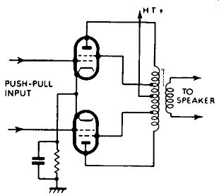
FIG. 3.15. Basic ultra-linear circuit.
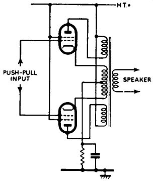
F1G. 3.16. Partial cathode loading, as used in the Quad II amplifier.
CATHODE LOADING
Total cathode loading of an out put stage (i.e., the load connected in the cathode instead of the anode circuit) results in I 00 percent negative feedback and calls for driver stages capable of supplying some 150 to 200 volts of signal. Whilst this method has received considerable attention, it is rarely used in hi-fi equipment. Partial cathode loading is used successfully, however (for example, in the Acoustical Quad II amplifier); see the circuit diagram in Fig. 3.16.
The cathode winding results in a portion of the output signal being returned to the grids in the form of negative feedback. A conventional negative-feedback loop is also incorporated and the combined effect gives rise to a low output impedance coupled with very low distortion at high power.
Cathode loading combined with ultra-linear operation has been experimented with in the United States (see Fig. 3.17), but the arrangement does not lend itself to class A operation, though quite low distortion figures, it is claimed, are possible by operating at class AB or class B.
SINGLE-ENDED PUSH-PULL
By the connection of two output valves in series and the application of a push-pull drive signal, the output impedance is somewhat reduced and rendered less critical than that of a more conventional stage. This idea lends itself to transformerless operation, meaning that a loudspeaker (of higher impedance than normal) can be connected direct to the output stage without introducing an output transformer.
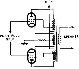
FIG. 3.17. Combined partial cathode loading and ultra-linear circuit.
This is not very suitable for Class A operation, but is of greater use
for Class AB and B operation.
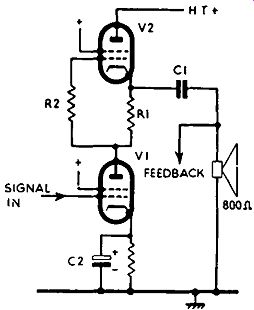
FIG. 3.18 The Philips version of the single ended push-pull output stage.
When it is realized that most of the non-linearity and phase shift (the latter limiting the amount of negative feedback in the power amplifier) are aggravated by the transformer, any device leading to its elimination is well worth consideration. We have already seen that a current of the order of one ampere is required in a 15-ohm loudspeaker to give 15 watts. While soon such a large current can be obtained easily by the use of an output transformer, very large valves would be required in order to obtain this current without a transformer, though matching could be secured by loading into the cathode circuits.
Experiments have been directed along these lines, but instead of using large valves a number of smaller valves have been tried. In one experiment 16 6AS7G valves were required to obtain 12 watts of power in a 16-ohm load. This is hardly economical, and one might well spend a lot of money on a special transformer.
Philips have solved the problem, however, by the use of two series connected output valves driven in push-pull and a speaker having an impedance of 800 ohms, against the conventional 15 ohms. The circuit is given in Fig. 3.18. When valves are connected in this way in an output stage, the circuit is often referred to as a single-ended push-pull stage.
Broadly speaking, the valves are biased so that they would pass equal current in the event of zero drive signal. When a signal is applied to the control grid of V1, however, this balance is disturbed at the frequency of the signal.
For example, a positive swing at the V1 control grid results in an increase in anode current and a reflected negative-going signal at the control grid of V2 with respect to cathode. In this way a push-pull signal is created and the valves are push-pull driven. The out-of-balance current at audio frequency flows through the loudspeaker coupling ( d.c. isolating) capacitor CI and in and out of the speaker's speech coil, as would be the case if it were connected across the secondary of a conventional output transformer.
In the Philips "Hi-Z" power amplifier, four valves are used in a parallel single-ended push-pull arrangement, and the speaker is fairly heavily damped by the low cathode impedance of V2.
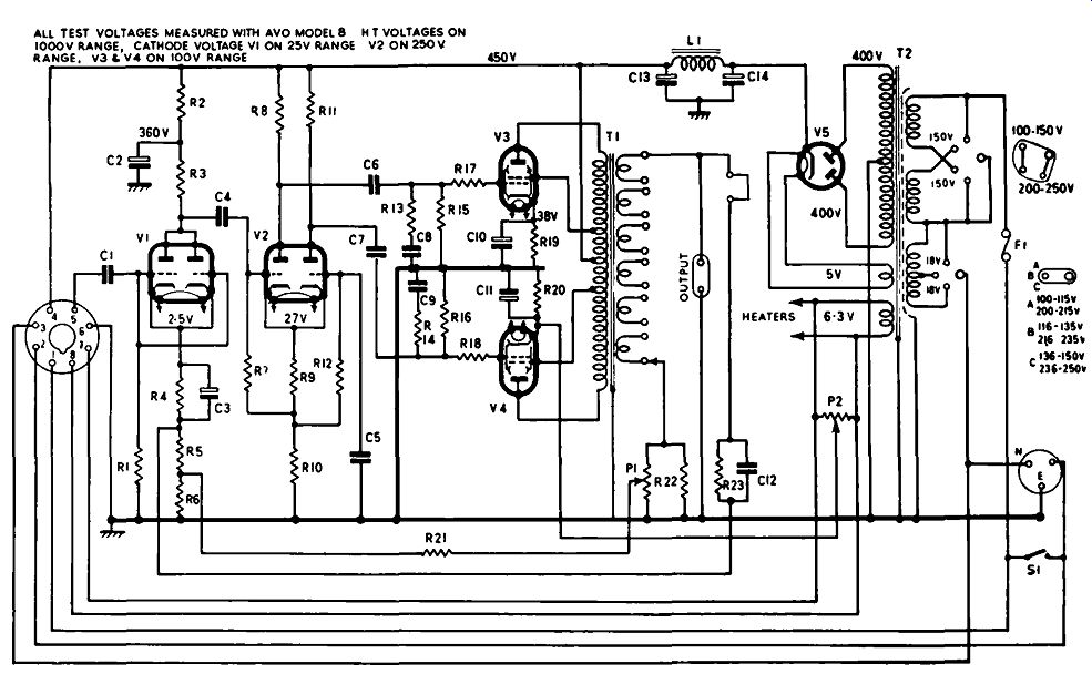
FIG. 3.19. Circuit diagram of the Pamphonic 2,001 power amplifier. The
negative-feedback loop is by way of R23 and C12, and the positive-feedback
loop by way of P1/R22 andR21. P1 serves as the damping-factor control.
THE POWER AMPLIFIER
There are various modifications of this circuit, some of which are driven from a phase-splitter stage which is designed along with the output stage to secure optimum balance of drive signal. In general, the systems cancel second-harmonic distortion by the distortions of each valve appearing in antiphase in the common load, though it is sometimes desirable to unbalance the distortions of the two valves, so that it is less in VI than in V2. This may be secured by shifting the working point of V2 away from that of minimum distortion or by applying negative feedback to VI by excluding a cathode bypass capacitor (i.e., removing C2).
APPLICATION OF FEEDBACK
The best way of getting to know the feedback loops is to study them in an actual circuit. In Fig. 3.19 is shown the complete circuit of the Pam phonic 2,001 power amplifier. Here stage V1 serves essentially as the first voltage amplifier. It raises the level of the signals from the pre-amplifier sufficiently to operate the cathode-coupled phase-splitter V2. This in turn drives the ultra-linear push-pull output valves V3 and V4.
Negative feedback is applied over the whole of the power amplifier by feeding back to the cathode circuit of V1 a suitable fraction of the signal voltage developed across the secondary of the output transformer T1. The phasing of the feedback is such that it is negative, while the degree of feed back is governed by resistor R23. C12 is usually known as a phase correction capacitor, whose purpose is to render the feedback loop very slightly frequency-selective (the capacitor is usually of fairly low value) and thus enhance the feedback stability margin. R23 and C12 are required to be altered in value so as to maintain optimum feedback on changing the loud speaker impedance tapping.
In transferring a signal in opposite phase from the reverse side of the secondary winding of the output transformer also to the cathode circuit of V1, a positive-feedback loop is provided. The positive-feedback signal is developed across R22 and Pl and fed back through R21. P1 is, in fact, a pre-set potentiometer which allows adjustment of the damping factor of the output stage. It will be recalled from the description of negative feedback in Section 2 that the output impedance as "seen" by the loudspeaker reduces as the negative voltage feedback is increased, and further reduces as the positive current feedback is increased. It is on this principle that the damping factor control operates.
To recapitulate, the damping factor is equal to the nominal output impedance of the amplifier divided by the impedance as "seen" by the loudspeaker (source impedance); a low source impedance results in a high damping factor and an infinite damping factor results when the source impedance falls to zero ohms.
EFFECT OF DAMPING FACTOR ON LOUDSPEAKER
A low source impedance or high damping factor affects the cone of a loudspeaker in much the same way as the shock absorbers affect the stability of a car. A car with worn or faulty shock absorbers oscillates vigorously up and down on riding rough ground or when a sudden stop is demanded. In the same way a high source impedance causes the cone of the loudspeaker to oscillate beyond the normal pattern of the audio signal when this is of the nature of sharp transients.
The effect is illustrated in Fig. 3.20. At (a) is a square wave which may be applied to the input of an amplifier, causing the loudspeaker cone to move rapidly in one direction as represented by A-B. Ideally, at point B the cone should stop dead and remain still until point C, when it should move rapidly in the opposite direction represented by C-D. This ideal will be approached when the amplifier source impedance as "seen" by the loudspeaker is very low (when the damping factor is high).
If the source impedance is high, however, there will be no electronic shock absorption, and the loudspeaker cone will follow the pattern as shown in Fig. 3.20b. Here, from A to B the cone will move rapidly in one direction, but instead of coming to a halt at B it will continue oscillating between B and C. It will change direction at C, but again oscillate about point D. This is known as a "damped oscillation", which may not only develop in the loudspeaker owing to a low damping factor, but may also appear as current oscillations in resonant elements of the amplifier. In this latter connection, the effect is often referred to as "ringing".
Apart from being damped electronically, the loudspeaker is also acoustically damped by the loading in its enclosure. It is said, therefore, that every speaker has a certain critical damping factor from the electronic aspect, and for this reason a large number of amplifiers are provided with a damping control. The author feels that a loudspeaker can be over-damped as well as under-damped, the effect in this case being like that of a light door coupled to one of those large automatic door-closing devices-the door can be neither opened nor closed sharply. The effect on the loudspeaker is that the cone is unable to follow very sharp transient waveforms.
This electronic damping effect can be demonstrated with a moving-coil milliammeter. With the terminals of the meter open-circuited, vigorous twisting of the meter will cause the pointer to oscillate in a very disturbed
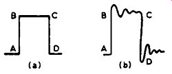
Fig. 3.20. A square-wave signal, as shown at (a), would cause cone oscillation
(b) as the result of insufficient damping.
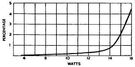
Fig. 3.21. Typical harmonic distortion curve for an amplifier rated
at a nominal 10 watts.
manner on its pivot; by short-circuiting the terminals, however, the pointer oscillation will be found to be considerably curtailed. The moving coil is damped by the low resistance shunt (short-circuit). This is one way of protecting such instruments during transit.
An infinite damping factor is when the source impedance of the amplifier "looks" to the loudspeaker as a dead short. In amplifiers having a damping factor control the setting corresponding to this condition can be established by feeding into the amplifier a 1,000 hz signal and adjusting the volume control until about 1-2 volts is measured across the loudspeaker terminals (an a.c. voltmeter is necessary). The damping factor control should then be adjusted whilst alternately disconnecting and reconnecting the loudspeaker. The position corresponding to an infinite damping factor is revealed by the output voltage remaining the same whether the speaker is connected or disconnected.
POWER OUTPUT
A hi-fi amplifier should be capable of supplying a speaker with at least 10 watts of power with a total harmonic distortion not exceeding 0.1 percent. Obviously, the amount of power required will depend upon not only the size of the room, but also the efficiency of the loudspeaker system. A speaker of 10 percent efficiency (a good figure) will produce only 1 watt of radiated acoustical power when connected to a fully loaded 10-watt amplifier, but this level of sound cannot be endured with any comfort in an average sized living room or lounge.
Most amplifiers are very conservatively rated, and quite a number of British instruments nominally rated at 10 watts can be pushed up to 14 watts without the distortion rising above 1 percent. This is illustrated by the typical distortion curve in Fig. 3.21; at 10 watts the distortion is in the region of 0.1 percent, and is still reasonably low up to 14 watts, but rises very seriously at greater outputs.
It is highly desirable for a high-power amplifier to have a margin of reserve power in hand before distortion becomes serious. For example, an orchestral peak of sound may increase the input signal voltage beyond that specified for maximum output. In the case of a 10-watt amplifier working at nearly full volume, such peaks will push the amplifier into heavy distortion.
In the case of a 30-watt amplifier adjusted for the same nominal sound intensity, however, the peaks will still be within the low-distortion power-handling range of the unit, and will be reproduced with equal fidelity as the low intensity sounds.
FREQUENCY AND POWER RESPONSE
The frequency response is taken as a measure of the deviation of output signal voltage as the input signal voltage is altered in frequency over and beyond the audio spectrum (see Fig. 3.14). The output voltage deviation is expressed in decibels over the frequency range employed. Unfortunately, the frequency response is usually given for a level considerably below the maximum power output of the amplifier. Thus, the response characteristic may be virtually level from, say, 10 hz to 20,000 hz at an output of 1 watt, but deviate considerably from this at full output.
An amplifier rated at 10 watts may give this figure at 0.1 percent distortion at 1,000 hz (the frequency at which measurement is usually made), but for the same distortion at 100 hz the maximum power may be only 5 watts. The distortion may well rise to 2 or 3 percent at 100 hz unless the input signal at and below 100 hz is reduced accordingly. This, of course, is a hypothetical consideration and to such a degree may not be common to all amplifiers; nevertheless, it indicates a need for a low-cut filter somewhere in the pre-output stages. To a smaller degree the same reasoning applies to the higher frequency end of the audio spectrum, but here the trouble is not as serious, as the higher-frequency signal components usually comprise low level harmonics.
POWER SUPPLIES
The mains transformer, rectifier, smoothing choke and filter components are mounted on the power-amplifier chassis, or on the power-amplifier side of a combination chassis. In the case of two-unit models, power for the pre amplifier is fed from the power amplifier by way of a multi-cored cable and plugs and sockets to suit the individual design.
Referring to Fig. 3.19, the mains transformer T2 has an adjustable primary winding to suit almost any mains supply, and three secondary windings. The h.t. winding is center-tapped and supplies 400 volts (with respect to chassis) to the two anodes of the h.t. rectifier valve V5. This is a straightforward full-wave rectifier circuit, which needs little comment. H.t. smoothing is provided by the smoothing choke L1 and the electrolytic capacitors C13 and C14, and a full 450 volts d.c. is present on the main h.t. line, which is also fed to the pre-amplifier power socket on point 4. The rectifier heater has its own winding supplying 5 volts a.c., and a 6·3-volt winding serves to supply the heaters of all the valves, the l.t. feed for the pre amplifier valves being taken to points 7 and 8 on the connecting socket.
The potentiometer P2 serves as a humdinger control. Apart from producing an exact balance in the heater chain, it also introduces a small positive bias to the heaters from the cathode of V4. Correct adjustment of this control can reduce the residual mains hum by as much as 20-30 db.
Adjustment is best made by connecting a sensitive a.c. voltmeter across the loudspeaker terminals, short-circuiting all the input terminals of the amplifier, and rotating the potentiometer for minimum reading on the voltmeter. The adjustment can also be made by ear for minimum hum level.
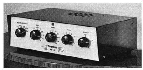
Fig. 3.22. The Pam phonic amplifier, Model 1,004.
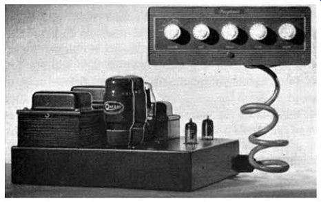
FIG. 3.23. The Pam phonic amplifier, Model 2,001.
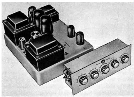
Fig.
3.24. The Pye Provost power amplifier, Model HF25, and the Proctor remote
control unit, Model HF25A.
Illustrations of three typical equipments are given in Figs. 3.22, 3.23 and 3.24. The Pamphonic Model 1,004 (Fig. 3.22) is a 10-watt combination unit, having a maximum distortion of0·5 percent at 1,000 hz at full output, and a frequency response which is substantially flat from 20 hz to 50 hz.
It has 20 db of negative feedback, and inputs for microphone, tape, radio and gram. Volume, contour (designed in accordance with the Fletcher-Munson curves), bass and treble controls are featured, the latter employing the Baxandall system. Provision is also made for a plug-in pick-up attenuator so that widely differing types of pick-up can be used. Three types of equalizing are catered for, selected on the main program-selector switch.
The Pamphonic Model 2,001 is a larger two-unit amplifier (Fig. 3.23), capable of giving a full 25 watts at very low distortion. This model incorporates all the features described in this and the previous section.
Fig. 3.24 shows the Pye "Provost" power amplifier and the associated "Proctor" remote control unit. This also has a power output of 25 watts with less than 3 percent harmonic distortion at 1,000 hz. At 15 watts the distortion is less than 0· l percent, but approaches 3 percent at 30 watts output.
The amplifier has an excellent frequency characteristic (see Fig. 3.14) and is substantially flat from 2 hz to 160 k hz. All the requirements of a hi-fi amplifier are catered for, including the Baxandall-type tone control and four recording characteristics, by the use of feedback networks (see Fig. 2.17). The power units of most hi-fi amplifiers are over-rated so that h.t. and l.t. can be fed to an auxiliary unit, such as a radio tuner. Provision is also usually available for the connection of a gram motor or tape recorder. A signal output socket is often to be found on the pre-amplifier or control unit. This is usually picked-up from the output of the voltage amplifier, after the tone-control circuits and before the volume control. This feature enables the program signal to be applied to the input of a tape recorder or additional amplifier.