The electrodynamic or moving-coil loudspeaker in hi-fi use today has exactly the same fundamental principles of operation as the first moving coil unit ever manufactured, and it remains as popular as ever.
However, whereas in early units the reproduction was severely "colored" by the limited frequency response and by disturbing resonances in the center of the audio spectrum, development over the years has resulted in the elimination of most of these shortcomings, at least in the better class of speaker.
There has been a reduction in all forms of distortion, the weight of the unit has been reduced and the overall efficiency increased by the use of new magnetic materials, while the main cone resonance has been pushed well down to the low-frequency end of the spectrum by improved methods of cone suspension. Although the response curve is by no means as sleek as that attributable to hi-fi amplifiers, there are twin-cone units which have a frequency range from 20 hz to 20,000 hz.
The moving-coil speaker has a strong magnetic field, produced by a permanent magnet, in which is placed a free-moving speech coil loaded by a cone. The speech coil moves axially either into or out of the magnet as the result of the signal current in the coil setting up a field which interacts with the magnetic field. The cone thus acts as a piston on the surrounding air and gives rise to pressure waves.
Apart from being proportional to the length of the conductor (the speech coil) and the signal current, the driving force-and hence the acoustic output-is also proportional to the strength of the field produced by the permanent magnet. The gauss is the measure of the field or flux density; 17,000 gauss being a typical value for a 10-inch unit. The total flux, however, is measured in maxwells, the gauss unit being equal to one maxwell per square centimeter. The strong magnets and large pole pieces of modern units create a total flux value approaching 200,000 maxwells.
The developments which have taken place in the production of permanent magnets have not only improved the electro-acoustic efficiency of modern loudspeakers, but have resulted in improved transient response and extended high-frequency performance. Smoothness of response over the audio spectrum is a very desirable characteristic of hi-fi units. Even though the overall response curve still has its ups and downs, the undulations of a good modem speaker are mild compared with those attributable to a general-service unit of a few years back.
Fig. 5.1 shows the response curve of the Model HF816 8-inch unit by Whiteley Electrical (WB Stentorian). A unique feature of speakers made by this firm is the universal-impedance speech coil, providing instant matching to transformers of 3 ohms, 7.5 ohms and 15 ohms. The response curve is made up of major and minor resonances over the frequency range. The major resonances can be dealt with from the loading aspect, but the minor resonances tend to give small coloration to the reproduction, and since these vary from speaker to speaker it follows that each speaker contributes its own characteristic sound to the reproduction. Normally, this coloration is not very noticeable when speakers are compared on a complex signal such as orchestral music, but if a white-noise signal is used, the difference in rendering of the wide-band signal is remarkable.
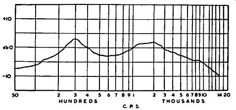
Fig. 5.1. Response curve of the WB 8-inch loudspeaker, Model HF816.
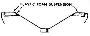
FIG. 5.2. The modern method of plastic foam suspension for loudspeakers.
CONE AND SUSPENSION
Both the character of the cone and its method of suspension on the loudspeaker chassis have a bearing on the various resonances evoked. The new plastic-foam method of cone suspension has brought about a much flatter overall response. The old method made use of a molded corrugated surround of cone material glued to the speaker chassis; the new method does away with the molded surround, and the periphery of the cone is suspended to the chassis by a soft plastic-foam material (see Fig. 5.2). This lighter suspension tends to damp the cone movement somewhat, and hence improve the transient response. It also reduces the main resonance to a very low frequency, and has the effect of alleviating cone break-up problems.
Cone break-up is essentially responsible for the irregular response towards the middle frequencies. At low frequencies, the whole cone moves up and down after the style of a piston, but as the frequency is raised its movement becomes so rapid that the direct energy of the actuating force is not simultaneously conveyed to the whole area of the cone. The movement towards the speech coil is reasonably faithful, but towards the periphery the amplitude of the movement decreases, and whole sections of the cone break up and vibrate in their own mode and phase, as governed by the driving frequency and inherent resonances. The effect is rather like the waves formed on a length of rope which is vigorously shaken up and down at one end.
Another approach to this problem is that of the General Electric Co., who have introduced a metal cone. The cone is made of Duralumin, and is thus light and rigid. There are shaped deformations over its area which tend to neutralize break-up and smooth the frequency response. Further irregularities in the middle-frequency range are reduced by a special "bung" which is secured to the pole piece. The effective working range of the speaker is from 30 hz to 20,000 hz. It has a maximum instantaneous power rating of 12 watts and a continuous power rating of 6 watts.
TWIN-CONE AND MULTIPLE UNITS
As a means of obtaining a wide overall response from a single unit, a twin-cone assembly is sometimes used. The main low- and middle-frequency range cone is so designed that above a certain frequency (known as the mechanical cross-over frequency) the speech coil effectively becomes decoupled from the cone and very little sound energy is produced by the main cone. However, tightly coupled to the speech coil is a very light and small cone which takes over at this point and maintains the response to the high-frequency end of the spectrum. The Axiom range of Goodman's loud speakers uses this principle. The Axiom 80, a 9½-inch unit, has a frequency range from 20 hz to 20,000 hz, while the 12-inch units have a range from 30 hz to 15,000 hz.
Instead of using a single loudspeaker to cover the whole range of audible frequencies, two or even three units may be used, each being designed to provide optimum results over a limited band of frequencies. This method eases the design problems associated with full-range units, eliminates undesirable compromises in design and brings about a marked reduction in intermodulation distortion.
Sounds occupying the low- and middle-frequency portions of the spectrum are served by an ordinary moving-coil unit of fairly large dimensions, while the top frequencies are catered for by a much smaller unit designed for a smooth response up to 20,000 hz. Some loudspeaker systems include an additional unit for the reproduction of the middle range of frequencies, in which case the low-frequency unit operates over the range of about 1,000 hz, at which point the middle-frequency unit takes over and responds up to about 5,000 hz. The high-frequency unit then gradually takes over and caters for the remainder of the spectrum. The names of "woofer", "squawker" and "tweeter" are sometimes given to the low-frequency, middle-frequency and high-frequency units respectively.
A frequency-dividing network (cross-over unit) is used to split the output between the loudspeakers so that there is no call upon any unit to handle large amplitudes of frequencies beyond its range. Since the change-over from one speaker to the next is gradual, and occurs at the cross-over frequency of the dividing network, each unit should be capable of handling at least half an octave beyond the cross-over frequency at full power, and two to three octaves beyond the cross-over frequency at reduced power. The type of dividing network utilized has some bearing on this.
Apart from improvement in the directivity characteristics and response to transients, multiple-speaker systems have a distinct advantage in the reduction of distortion arising from the Doppler effect. Briefly, the Doppler effect is that of an increase in frequency when the source of the signal is advancing and a decrease when it is receding. We have all heard the change of pitch of a whistle of a railway engine when it passes through a station at considerable speed; this is an example of the Doppler effect from the aspect of sound waves-the greater the velocity of the source of the sound ( or radio signal), the greater the change in frequency.
So far as the loudspeaker is concerned, the movement of the cone at low and middle frequencies is often of the order of plus and minus ¼ in. and, depending upon the actual frequency, the velocity of the cone is of considerable value. If, while the cone is being actuated by a relatively low-frequency sound, there is introduced a sound of greater frequency, then this will suffer a change in pitch since the source of the sound is moving at high velocity, and a Doppler discord will result. During the time that the cone is moving forward under the control of the low frequency, the pitch of the high-frequency sound will appear to increase at the front of the speaker, and decrease at the rear, thus doubling the net effect of the discord between the two surfaces of the cone. If the frequencies are segregated over a number of loudspeakers, the distortion is considerably reduced.
MIDDLE- AND HIGH-FREQUENCY UNITS
Ordinary 8-inch or 10-inch moving-coil units are often used to cater for the middle frequencies, and these are quite successful provided a good cross over unit is adopted. There are, however, more specialized pressure-driven horn-loaded units, such as the Goodman's "Midax". This has a frequency range from 400 hz to 8,000 hz, the recommended cross-over frequencies being 750 hz and 8,000 hz, and it can handle something like 25 watts (British rating). Pressure units are often used for the reproduction of the middle and high frequencies in conjunction with a horn for the purpose of increasing the acoustic loading on the cone or diaphragm. The pressure unit is, in effect, a moving-coil loudspeaker, but employing an aluminum-alloy diaphragm instead of a conventional cone. This reduces the mass, which is desirable for high-frequency work, while permitting easy pressure loading to the horn.
The horn is usually of exponential nature, though other shapes, such as conical or parabolic, are sometimes used. The overall length of the horn determines the lowest frequency at which it will load adequately. For a reasonable low-frequency response the horn may have to be several feet in length. For the middle range of frequencies, the length is less of a problem (the overall length of the Midax is 18-9/16 in.), while for the high frequencies, a horn length of a few inches is all that is required.
Since horn loading increases the efficiency considerably above that of direct-radiator moving-coil units, variable attenuators are usually required in the lines feeding the horn-loaded units, so that the sensitivities can be easily matched.
Apart from horn-loaded pressure units using a diaphragm, ribbon loud speakers are sometimes used, also in conjunction with a horn, for the faithful reproduction of high frequencies. This type of unit has a very thin corrugated aluminum ribbon suspended in a powerful magnetic field. The ribbon itself serves as the conductor, being analogous to the speech coil of conventional moving-coil units, and through this are passed the audio-frequency currents from the output transformer. The ribbon vibrates in sympathy with the original sound, and is pressure-loaded to a small horn of dimensions to match the higher audio frequencies.
PLESSEY IONOPHONE
A remarkable high-frequency reproducer which has no moving parts at all is the Plessey ionophone, an invention of Mr. S. Klein of Paris. The functional portion of the unit is a small quartz-glass tube. One end of this is open and the other drawn down to a small hole in which is inserted an electrode known as the "Kanthal" (see Fig. 5.3).
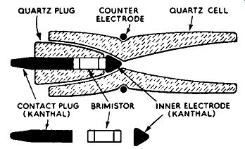
FIG. 5.3. The functional portion of the Plessey ionophone.
A glow discharge is arranged to take place in the air within the open end of the tube by applying a high voltage at radio-frequency across the Kanthal contact plug and the outside counter electrode. The r.f. oscillator providing the discharge voltage is modulated by the amplifier's a.f. signal, and since the intensity of the discharge at any instant is proportional to the instantaneous value of the applied r.f. voltage, the glow discharge will vary in sympathy with the a.f. signal. Because one end of the quartz tube is closed, pressures varying in sympathy with the a.f. signal will be set up in the open end of the tube, and these are conveyed directly to the mouth of an exponential horn for resolution into sound waves, of frequency range governed by the dimensions of the horn.
The Plessey unit is designed to work into a cross-over frequency of some 2,000 hz, and from this frequency the response is perfectly smooth up to about 17,000 hz. Since the arrangement uses no moving parts, the response to transients approaches the theoretical ideal.
The oscillator unit is built into the rear of the horn mounting, and is arranged to operate at 27 Mhz, while the power-pack and modulation transformer are carried separately. Fig. 5.4 shows the unit in more detail, and its connection to the output circuit of the oscillator, while Fig. 5.5 gives a suggested arrangement for the cabinet mounting of the ionophone, power-unit and Plessey 15-inch loudspeaker for reproduction of the frequencies below the 2,000 hz cross-over.
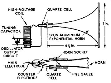
FIG. 5.4. Connection of the ionophone to the output circuit of the r.f.
oscillator.
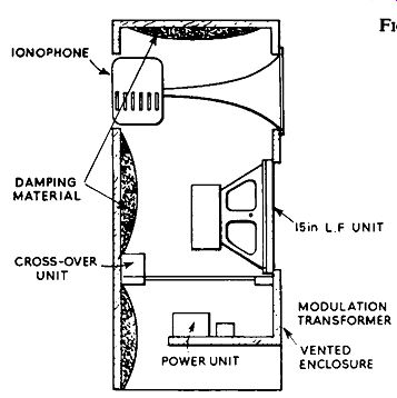
FiG. 5.5. Suggested cabinet and mounting for the ionophone.
ELECTROSTATIC UNITS
Of recent years considerable attention has been focused on the electro static type of loudspeaker and its potentialities as a full-range unit. High frequency electrostatic units have been available for a number of years, and are adopted in a number of commercial radio sets, as well as in hi-fi loud speaker systems. The principles involved for the reproduction of sound by this means are not new by any means, but the development of sound reproduction has revived interest in electrostatic units, formerly known as "condenser loudspeakers".
As will be seen from the basic arrangement of a simple unit in Fig. 5.6, two plates are used, as in a capacitor. One plate is fixed and perforated, while the other is very thin and movable, and mounted in such a way that it can vibrate without touching the fixed plate. In some designs the loudspeaker is curved to widen the angle of sound radiation.
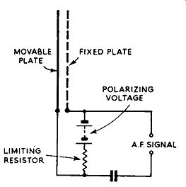
FIG. 5.6. Basic arrangement a simple electrostatic loudspeaker.
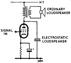
FIG. 5.7. One method by which an electrostatic.
The signal from the output stage of an amplifier (at high impedance) is applied across the two plates, sometimes through an isolating capacitor (as in Fig. 5.6). A fairly high voltage varying at the signal frequency is thus present across the plates, and this gives rise to mechanical forces which cause the thin movable plate to vibrate in sympathy with the sound signal. This is the normal electrostatic action. Under this condition, however, the movable plate will be attracted towards the fixed plate on every half-cycle of the signal, and two vibrations will occur on each full cycle. To avoid this useless function a polarizing voltage is applied along with the signal, across the plates, as shown in Fig. 5.6. The polarizing voltage causes an initial attraction SIGNAL IN of the movable plate towards the fixed plate, and provided the peak signal voltage does not exceed the polarizing voltage, the plate will vibrate in correct unison with the signal pattern. The limiting resistor in the circuit prevents ELECTROSTATIC LOUDSPEAKER the low-impedance polarizing source from short-circuiting the signal.
For the simple application of an electrostatic unit, the h.t. voltage at the anode of the output valve can be used as a polarizing voltage, as shown in Fig. 5.7. This voltage is varying at the signal frequency, and is fairly high (and at high impedance)-which is just what is required.
More elaborate electrostatic units employ a push-pull system (sometimes known as bilateral) in which the movable plate is situated ~tween two fixed plates (Fig. 5.8). This idea is extended to full-range units, such as the Quad electrostatic loudspeaker (developed by P.J. Walker, of the Acoustical Manufacturing Co.). The two fixed plates are energized by equal and opposite signal voltages from the secondary of a push-pull transformer, the primary being connected to the signal source. The polarizing voltage is applied, along with the signal as already described, from a small e.h.t. generator. As current is not required for this operation, a simple generator similar to that used in certain television receivers is all that is required.
Electrostatic units can be loaded either by a horn or by an ordinary reflex cabinet, but certain designs provide automatic loading and do not usually require artificial means.
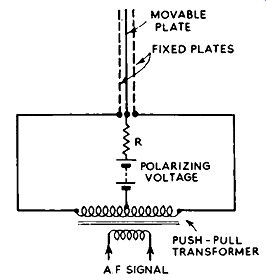
FiG. 5.8. Push-pull electrostatic system.
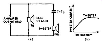
(Left) Fig. 5.9. Simple method of connecting a tweeter (a), showing its
operating curve (b). (Below) Fig. 5.10.
Showing how a tweeter volume control can be introduced.
A high-frequency unit or tweeter can be added easily to any loudspeaker system to augment the high-frequency response, as shown in Fig. 5.9 (a). In effect, the tweeter is supplied by way of capacitor C, the reactance of which decreases with rise in frequency, and thus limits the current in the speech coil at low frequencies. The curve in Fig. 5.9 (b) illustrates the action graphically.
If the tweeter is required to start taking over at about 5,000 hz, then at this frequency the reactance of C should equal the impedance of the tweeter.
Excluding any inductive effects of the tweeter's speech coil, and assuming an impedance of 15 ohms, a capacitor of 2 mF will serve the purpose (a 2-mF capacitor has an impedance of 15 ohms at 5,000 hz). Under this condition, the current in the tweeter's speech coil at 5,000 hz will be approximately 30 percent below that in the speech coil of the bass unit: 5,000 hz can thus be considered as the cross-over frequency (or more accurately, the take-over frequency). If the speech coil impedance is, say, 7.5 ohms, or if a tweeter volume control is used, as shown in Fig. 5.10, and the "effective" impedance of a 15-ohm tweeter is reduced approximately to 7.5 ohms, then the value of C should be doubled. The same applies if it is required to lower the "take-over" frequency one octave when using a 15-ohm unit.

Fig. 5.11. Simple quarter-section cross-over filter (a), and its operating
curve (b).
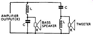
FIG. 5.12. Circuit of a half section cross-over filter.
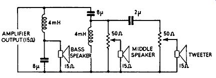
Fig. 5.13. A more elaborate arrangement for three speakers.
In the circuit in Fig. 5.11 (a) a choke L has been interposed in series with the bass speaker, the treble section remaining as in Fig. 5.9 (a). An inductor or choke has a reactance which is opposite to that of a capacitor; it rises with increase in frequency, and thus limits the amount of current in the speech coil of the bass unit at high frequencies. In this way a simple quarter section parallel cross-over filter results. Provided all the impedances are 15 ohms and essentially resistive (which, unfortunately, is not always the case in practice), a 5,000 hz cross-over can be secured by using an inductor valued at 0.5 mH and a 2-mF capacitor. The curves in Fig. 5.11 (b) illustrate the operation of the filter. These show that the current in the speech coils of both units at the cross-over frequency is 3 db below full current. This has little effect on the acoustical power, since both units will be contributing towards the total sound more or less equally.
This simple quarter-section filter is not always favored owing to each section having an attenuation of only 6 db per octave at the cross-over frequency, and the greater attenuation of a half-section arrangement is often preferred. The circuit of such a network is given in Fig. 5.12. It will be seen that it is very similar to the quarter-section filter already given, but it has the addition of an inductor across the tweeter and a capacitor across the bass unit.
The result of having these is to speed up the rate of attenuation at the cross-over region by a further 6 db per octave, thereby giving a total rate of attenuation of 12 db per octave.
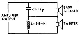
FIG. 5.14. Quarter-section series cross over network. With 15-ohm speakers,
the component values given provide a 1,000 hz cross-over.
As this kind of filter is extensively adopted, the following expression relating the component values with the cross-over frequency will be useful:
R 103 l(mH)=-- pi fc v2 )08 C(mF) = 2 pi fc Rv2
… where R is the common impedance of the amplifier output and speakers in ohms and Jc is the cross-over frequency in hz.
Fig. 5.13 shows a more elaborate network suitable for three loudspeakers, in which the bass and middle units cross-over with a 12-db per octave slope, while the tweeter has a 6-db per octave take-over.
There are a host of cross-over networks, ranging from the simple high pass/low-pass arrangement forming the quarter-section parallel system already discussed to a complex full-section arrangement incorporating three inductors and three capacitors. So-called "series" and "parallel" formations are used in practice. A quarter-section series network is given in Fig. 5.14, which makes interesting comparison with the quarter-section parallel circuit in Fig. 5.11. Similarly, the half-section series network in Fig. 5.15 can be compared with the half-section parallel network in Fig. 5.12.
The values given to the components in the circuits in Figs. 5.14 and 5.15 provide a cross-over in the region of 1,000 hz when used with 15-ohm speakers. Since the component values are inversely proportional to the cross over frequency, the cross-over is lifted an octave by halving the values, and dropped an octave by doubling the values. If the speaker impedance is halved, the capacitor values should be doubled and the capacitor values halved, to maintain the cross-over frequency for 15-ohm units.
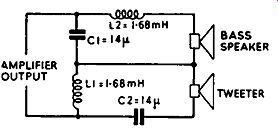
FIG. 5.15. Half-section series cross-over network. With 15-ohm speakers,
the component values given provide a 1,000 hz cross-over.
All the networks given are of the constant-resistance type, since these are preferred by most equipment manufacturers and users. It should be noted, however, that all cross-over networks are much of a compromise even though they perform well in practice-since the impedance of the speech coils of the loudspeakers is not maintained at a constant 15 ohms throughout the audible range. The theoretical ideal is to employ a power amplifier for each speaker, the high-frequency amplifier and speaker being fed from the pre-amplifier by way of a high-pass coupling, and the low-frequency amplifier and speaker through a low-pass coupling, each coupling being arranged to have the required characteristic shape and attenuation rate.
SPEAKER PHASING
Two or more speakers are in phase when their cones move together in perfect unison under the control of the same signal. If one cone moves in while the other moves out, then the speakers are exactly 180 deg. out of phase. Intermediate phase displacements occur between these two extremes.
For example, at the cross-over frequency, a quarter-section cross-over network usually introduces a phase displacement of 90 deg. For this reason, it is often desirable to position the tweeter one-quarter of a wavelength behind the plane of the bass unit, so that the sounds from the two units reach the ears of a listener at the same time (provided the speakers are phased correctly from the d.c. point of view). A cycle-lamp battery can be used to check this, as already described.
Incorrect phasing often gives the effect of "emptiness", "disembodied treble", lack of bass or lack of middle register, depending upon the frequency range fed to the units and the acoustics of the listening room.
MATCHING
An amplifier can only give its maximum undistorted output when the loudspeaker system represents a perfect match to its output terminals. If two 15-ohm units are connected in parallel across the output terminals, then the speaker impedance as "seen" by the amplifier is 7·5 ohms. Similarly, two 15-ohm units connected in series add up to a total impedance of 30 ohms, and in both instances the impedance adjustment on the amplifier must be altered to correspond.
Generally speaking, it is not a good idea to connect two hi-fi speakers in series, even though the amplifier output is adjusted to match the sum of the two impedances. The reason for this is that the actual resistances of the speech coils are also added in series, which has an adverse effect on the damping mechanism.
From Section 2 it will be recalled that the resistance of the speech coil represents the dominant impedance at high damping factors. When the two speakers are connected in series, each speaker "sees" something like 30 ohms its own resistance in series with the resistance of the other speaker across the low source resistance of the amplifier. When they are in parallel, however, each speaker "sees" only its own resistance of 15 ohms or thereabouts.
In other words, the introduction of another series-connected speaker is as futile as putting a resistor in the speech-coil circuit, and then trying to damp the actual speaker by reducing the source impedance of the amplifier.
Speakers connected in series tend to have a very poor transient response, and disconcerting "hangover" effects will develop. The same applies with series-parallel networks. These arrangements may suit public-address systems, where ease of connection of speaker units is demanded, but they should not be used with hi-fi or sound-reinforcement equipment.
BAFFLES AND VENTED ENCLOSURES
Sound is emitted from both sides of the cone of a loudspeaker, and as a compression wave is formed on one side, a rarefaction wave is formed on the other side. At the lower frequencies, where the wavelengths of the sound waves approach the dimensions of the cone, sound waves from the rear tend to cancel sound waves from the front and the acoustical response of the unit diminishes almost to zero as the frequency is lowered. This undesirable effect can be avoided by mounting the unit on a baffle board so that the rear and front sound waves are isolated. Since the baffle cannot have infinite area, front-to-back cancellation will occur at some low frequency-governed by the dimensions of the baffle used. So that the cancellation will not be common in all dimensions, as in the case of a circular baffle on which the speaker is mounted in the exact center, a rectangular baffle should be used and the speaker displaced from the center.
A near approach to the infinite baffle is secured by mounting the speaker on a wall dividing two rooms. This idea is used by many enthusiasts, and will be encountered from time to time by the technician. Disconcerting irregularity of response can be evoked by this method, however, unless the hole in the wall is beveled so as to avoid the cylinder formed by the wall thickness from resonating. Some enthusiasts make an extra large hole and introduce a small sub-baffle on which the speaker is mounted.
Baffles for treble and middle units need not be as large as their counter part for the bass unit, though they should be large enough to respond down to an octave below the cross-over frequency.
A synthetic method of providing infinite baffle characteristics is to enclose the rear of the loudspeaker in a substantial air-tight box. The air trapped in the box acts as a cushion on the cone and thus provides acoustical damping, whilst also reducing the main cone resonance, depending upon the volume of the box.
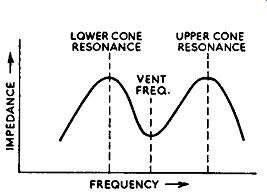
Fig. 5.16. Impedance characteristics of a speaker correctly loaded by
a reflex enclosure.
A vented enclosure encloses the rear of the loudspeaker, is formed of a substantial box and has a vent hole cut in one of its walls, usually near the speaker aperture. The enclosure thus acts as a resonator (see Section 1), the resonant frequency being governed by the volume of air within the enclosure and the area of the vent. The effect that this has on the loudspeaker and acoustical response is rather interesting. At the resonant frequency of the enclosure most of the sound is radiated by the vent and the speaker cone is subjected to maximum acoustical damping. For this reason it is often advantageous if the cone and enclosure resonances coincide in frequency. An increase in low-frequency radiation is secured whilst the disturbing effect of the speaker resonance is alleviated. This, however, represents an ideal situation.
As the frequency decreases below the resonance of the enclosure, the output from the vent falls off, but the output from the speaker rises due to a lowering of its resonant frequency as the result of the air-pressure build-up between cone and vent. However, since the sounds from the two sources approach the anti-phase condition, the resultant sound output diminishes fairly quickly, and no useful increase in bass response is obtained by lowering the resonance of the loudspeaker.
As the frequency rises above the resonance of the enclosure, the loading on the speaker cone is lifted and its resonant frequency rises. Output from the vent tails off and the normal middle- and high-frequency characteristics of the speaker take over.
From the foregoing it will be realized that two auxiliary resonances of the cone occur on either side of the enclosure resonance. These are often illustrated in the form of a curve as shown in Fig. 5.16.
MEASURING SPEAKER IMPEDANCE
As an impedance curve of this kind provides useful information with regard to the loading of a speaker by its enclosure, it will be instructive at this stage to consider a method by which speaker impedances can be taken.
Precise results require the use of an impedance bridge, but as such an instrument is not generally available to the enthusiast or technician other methods less exacting but practicable, will be described.

FIG. 5.17. Set-up for measuring speaker impedance.
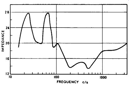
FIG. 5.18. Experimental impedance curve of Goodman's Axiom 12-inch unit,
Type 150, Mk. ll, in a reflex enclosure which has a 1 ½-inch slate front.
Fig. 5.17 shows a set-up which utilizes the Ohm's Law method. The voltage across the speech coil and the current in it are measured throughout the frequency range by the a.c. voltmeter V and the a.c. ammeter A. The test signal is provided by an audio oscillator, and the necessary power produced by the amplifier (any good hi-fi amplifier will serve). The impedance value at any frequency is computed by dividing the voltage reading by the current reading (in volts and amps). Thus, if 3 volts at 0.2 amp. are indicated, the speaker has an approximate impedance of 15 ohms at the frequency of the test.
Fig. 5.18 shows an experimental impedance curve using the above method of measurement. The speaker unit was a Goodman's Axiom 150 Mk. II, and was mounted in a reflex enclosure having a slate front of 1 ½ in. thickness.
It will be seen that the two resonance peaks either side of the enclosure's resonance are nicely spaced and of equal amplitude, indicating that the speaker is ideally loaded by the enclosure.
Another method of checking impedances (see Hi-fi News, February, 1957) is shown in Fig. 5.19. Here a 30-ohm 1-watt resistor is interposed in the speech-coil circuit and the voltage across it measured by a Model 40 A voltmeter set to the 2.5-volts a.c. range. The speaker terminals are short-circuited and the oscillator and amplifier controls adjusted to give full-scale deflection--making sure that the oscillator is not overloading the first stages of the amplifier. The short-circuit is then removed, and the impedance of the speaker in ohms, at any particular frequency, is given on the "ohms" scale divided by 100. Thus, if the meter reads 2,000 ohms on the scale, the impedance is 20 ohms.
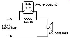
FIG. 5.19. Another method for impedance measurement, using a Model 40
Avo meter.
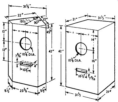
Fig. 5.20. Suggested en closures for the TSL Lorenz LP 312-2 wide-range
speaker system.
The signal voltage from the amplifier must remain constant throughout the frequency test range, but this can be monitored, if necessary, by an a.c. voltmeter or on an oscilloscope. The output voltage from most hi-fi amplifiers is reasonably consistent over the frequency spectrum, provided the oscillator voltage applied is constant.
A few words of warning: the impedance curve is not an indication of acoustical output from the speaker. The only way that this can be assessed is by measuring the sound field produced by the speaker system. Since quite a lot of sound comes out of the loudspeaker during impedance tests, first make sure that the neighbors are out or that the test room is sound-proof! Even though hi-fi enthusiasts experiment late into the night, be absolutely certain that the neighbors are not in bed, for it is surprising how the bed springs can resonate when the oscillator is tuned to the critical frequency and plenty of watts are emitting from the speaker-even though the springs are heavily damped by the bedding.
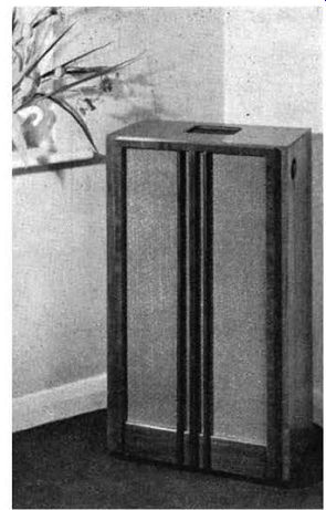
FIG. 5.21. The Pamphonic Victor speaker system. This has a treble unit
at the top, the volume of which can be controlled from the side of the
cabinet. The preferred position for this system is in the corner of a
room.
ENCLOSURE CONSTRUCTION AND DIMENSIONS
Reverting to enclosures, the cabinets should be of solid and rigid construction. A 1-in. wall thickness is desirable, though double walls of thinner material can be used if the space between the walls is filled with dry sand. At least three walls, at right-angles to each other, should be lined to a depth in excess of 1 in. with sound-absorbing felt or plastic foam, as a means of reducing standing waves within the enclosure. Acoustic curtains are hung in the enclosure for the same reason.
The size of a reflex cabinet, for a given low-frequency response, can be reduced by the inclusion of an acoustical filter over part of the vent. Such filters take various forms, one type being marketed by Goodmans under the name "acoustical resistance unit". The filter reduces spurious resonances, while also minimizing the magnitude of the upper resonance which, as we have seen, is a characteristic of conventional reflex enclosures.
In Fig. 5.20 is given the dimensions for suggested enclosures for the TSL Lorenz Type LP 312-2 loudspeaker system.
This is a 12-inch unit, which also incorporates two Lorenz Type LPH 65 treble units mounted in front of the cone. Its overall frequency response is from 20 hz to 17,000 hz.
Fig. 5.21 shows the Pamphonic "Victor" speaker system.
Apart from the large bass unit, this has a cone-type treble unit at the top of the enclosure. A cross-over network is contained in the enclosure, and the treble unit is fed by way of an attenuator which can be adjusted to give the correct degree of "presence". The treble unit is fully enclosed so that there is no interaction between the two sound sources, and it is mounted at an angle so that the sound is directed towards the corner of a room, whence it is deflected into the room at large.
OTHER ENCLOSURES
There are numerous other enclosures and speaker-loading devices used by enthusiasts, full constructional details of which are given elsewhere (i.e., in manufacturers' literature and in "Sound Reproduction" by G. A. Briggs). It is not intended to study them all here, but a few words on the more popular arrangements will not be amiss.
The exponential horn in relation to treble and middle-range speakers has already been mentioned. Whilst this system represents the most efficient way of loading a speaker, its large size at the lower frequencies is a dis advantage. Nevertheless, horn loading in the bass is adopted, usually by folding the horn in various ways within an enclosure.
The tuned-pipe arrangement is worth consideration. The pipe has one closed end and is critically dimensioned so that a fundamental anti-resonance occurs at the frequency of the major low-frequency resonance of the speaker.
This gives the system a characteristic similar to that of the reflex enclosure, whilst being less difficult to manufacture. The principle of operation is rather like that of an organ pipe, though in some cases the pipe is tapered and the speaker mounted one-third of the overall length away from the closed end.
At resonance the sound radiated from the open end is out of phase with that radiated from the cone.
The acoustical labyrinth is a type of enclosure which avoids resonance effects, but has a slight falling off at the low-frequency end of the spectrum. It consists essentially of a very long pipe (about 11 ft.), heavily lined with a thick felt or other acoustic damping material, and has the effect of completely absorbing radiations from the rear of the cone.
Another method of securing adequate low frequency performance is by the use of a battery of some nine speaker units mounted on a wood baffle with short sides, which is left open at the rear. This idea is sometimes used by American enthusiasts .

FIG. 5.22. The Pamphonic line-source loudspeaker system, showing how
the speaker units are mounted in a straight line one above the other.
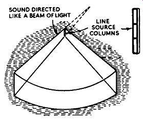
FIG. 5.23. The sound is radiated from a line-source speaker system rather
like the flat broad beam of light emitted from car fog lamps.
LINE-SOURCE SPEAKER
One type of loudspeaker system, used particularly for sound-reinforcement applications rather than domestic hi-fi work, consists of several speaker units mounted close together one above the other in a wood or metal enclosure, depending on whether it is to be used indoors or outdoors. In the latter case the enclosure is weather-proofed. These loudspeaker systems are sometimes called "sound columns", and by Pamphonic Reproducers, Ltd., "line-source loudspeakers". Fig. 5.22 shows the Pamphonic system, with the units mounted one above the other. All the units are connected in phase, and the small units are connected by way of a suitable cross-over network to cater for the high frequencies.
The reason for mounting the units in a straight line is to secure a directional effect in the radiated sound rather like the flat, broad beam of light emitted from certain car fog lamps (see Fig. 5.23). Whilst the length of the column does not affect the horizontal distribution, which approximates 120 deg., it does affect the vertical distribution-the longer the column the smaller the vertical angle of distribution and the more concentrated the vertical distribution of the sound.
The greatest advantage of this concentrated distribution is that very little sound energy is wasted unnecessarily outside the range of the listeners. This leads not only to greater efficiency, but also avoids difficult reverberation problems which always arise in lofty buildings when fairly high-level sound is provided by single-source speaker systems. Service technicians having experience of public-address installations in swimming baths and churches will appreciate how the hard reflecting surfaces of such buildings evoke many indirect reflected sounds as well as the directly radiated sound. In extreme cases, speech is made almost unintelligible. Line-source speaker systems alleviate this trouble to a large degree owing to the reduced radiation of superfluous sound.
During tests with Pamphonic line-source equipment in St. Paul's Cathedral, the improved efficiency of line-source speakers was demonstrated by the fact that a power-input of only one watt provided sufficient sound from one 11-ft. line-source speaker standing beside the pulpit to cover the whole dome seating area of 9,000 sq. ft.
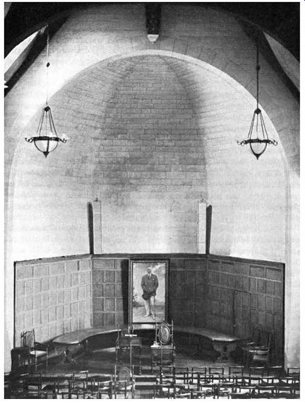
FIG. 5.24. Two Pamphonic line-source speakers mounted in the rear of
the dome of Rhodes House, Oxford, in connection with the Duke of Edinburgh's
Study Conference held there. The installation was carried out by Lowe & Oliver
Ltd.
Another advantage of the system is that a listener situated close by a column is not disturbed by a very high sound level as he would be close by a high-level single source unit. Because the intensity of sound at a short distance from the column is less than the sum of the sound intensities of all the units, acoustical feedback between the microphone and line-source speaker represents less of a problem than when single-source units are adopted. The microphone can, in fact, be brought remarkably close to a line-source unit before feedback takes place, even when the amplifier's gain control is set for a normal level of reinforced sound.
For a large number of installations a single line-source unit is all that is required, for both indoor and outdoor use, and from the practical aspect this saves considerable time with regard to the wiring of the installation, as compared with the wiring of a large number of single-source units to provide the same coverage of sound.
Fig. 5.24 shows two Pamphonic line-source units mounted in the rear of the dome of Rhodes House (Oxford) during the course of the Duke of Edinburgh's Study Conference held there in 1956. Fig. 5.25 shows the neat installation of an outdoor unit, mounted on a specially-designed pole and stand.
GEC PERIPHONIC LOUDSPEAKER SYSTEM
The periphonic loudspeaker system evolved by the General Electric Co. is based on the GEC metal-cone speaker units in conjunction with a system of GEC presence units and a cabinet specially designed to eliminate all structural resonances, whilst also exploiting the enhanced bass response of the periphonic principle. In effect, there are two metal-cone units mounted in a V-shaped enclosure, the units being powered in such a way that the cones are driven in push-pull (from the mechanical aspect). This results in cancellation of any residual harmonic distortions produced in the cones themselves, and reduces the total second- and third-harmonic distortion to some 2.7 percent at 40 hz. This is remarkable when it is compared with the 40-percent distortion of this nature produced in a paper cone unit at the same frequency and power.
Four presence units are installed at the front and sides of the cabinet, which can be switched if required so as to alter the apparent nearness of the orchestra to individual listening requirements and conditions. ~I
The presence units are fed through cross-over networks.
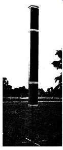
FIG. 5.25. Outdoor version of Pamphonic line-source loudspeaker unit.
SOUND DISTRIBUTION
Although up to the frequencies of about 1,000 hz a loudspeaker functions as a spherical radiator and has a radiation angle of almost 180 deg., at high frequencies the whole area of the cone or diaphragm is unable to serve as a "piston" on the surrounding air. Radiation of the sound thus becomes confined to a narrow beam, whose diameter reduces as the frequency is raised. This is because the area of the cone responsible for the high-frequency radiation progressively diminishes towards the speech coil with increase in frequency.
Various devices are available for diffusing the high frequencies and thus preventing this beaming effect. A simple, though effective, method takes the form of directing the sound from the treble unit into the corner of the room, whence it is scattered into the listening area. It will be recalled that this idea is adopted in the case of the Pamphonic Victor loudspeaker system.
Another method which appears to be gaining popularity is the use of reflectors of various shapes positioned in front of the cone of the treble unit.
The Burne-Jones tweeter unit incorporates this idea. The tweeter unit proper is housed in an attractively finished wood cylinder having three wide-spaced feet so that it can be unobtrusively positioned on top of the normal enclosure.
The sound is emitted from the top of the cylinder by way of a horn-loading system of very small dimensions, and full omni-directional radiation in the horizontal plane is secured by a cone-shaped reflector, styled in the form of a mushroom, mounted on top of the cylinder. The unit carries a cross-over network and balance control, and has a frequency response from 2,000 hz to 18,000 hz.
Apart from a cone, other shapes can diffuse the high frequencies to any particular pattern, though it should be remembered that simple geometric reflection of sound occurs only when its wavelength is small compared with the dimensions of the reflector. The Lowther Type PM6 high-frequency unit has a diffuser actually installed at the center of the cone.
Another method of evoking dispersion of the high-frequency beam is by means of a so-called acoustic lens mounted in front of the treble or middle range unit. Theoretically, an acoustical lens serves to bend sound waves just as an optical lens bends light rays and a radio lens bends radio waves. Since we have a narrow sound beam to start with, however, and it is required to radiate this over a greater angle, the acoustical lens is arranged to be of the divergent type.
The lens is formed of an array of slant plates through which the sound has to pass. The distance between the plates and their angle of slant determine the frequency of operation of the lens and its comparable refractive index.
Since the slant has the effect of extending the path of the incident wave in relation to the normal path of the wave, the waves undergo an effective change in velocity on passing through the lens, and on leaving thus tend to either converge or diverge from normal, depending upon how the lens is designed.
The high-frequency limit of the device is governed by the spacing of the plates in terms of half a wavelength, while the refractive index is given by the reciprocal of the cosine of the angle of slant.
Since it is necessary for the lens to receive as near an approximation of a plane wave as possible for correct operation, acoustical lenses are usually associated with horn-loading, which satisfies this condition. The Westrex high-frequency horn-loaded unit "Acoustilens" very successfully combines horn-loading and the acoustical lens principle.
ADJUSTMENTS TO SPEAKER SYSTEMS
Properly used, it is very rare these days for the loudspeaker unit to require detailed attention. However, should a definite fault develop, it is often best to return hi-fi units to the maker for reconditioning. This procedure is not usually necessary with the less expensive types, and with those units falling outside the accepted hi-fi definition.
Complete failure is an almost certain indication of an open speech-coil circuit. Before getting the cone and speech-coil assembly replaced, however, careful attention should be given to the flexible leads connecting the speech coil to the terminal block or tags for, apart from a definite burn-out caused by a severe overload, these are the most vulnerable trouble points. If the speech coil is definitely open-circuit, as can be determined by making a continuity check at the points of connection of the flexible leads on the cone, either a replacement can be obtained from the manufacturer, complete with cone, and fitted in the workshop, or the unit can be sent to the maker or a firm specializing in speaker repairs.
Probably the most common of all speaker troubles is an out-of-center speech coil, resulting in its fouling the pole pieces of the magnet. This trouble can easily be established by grasping the cone at diametrically opposite points and gently moving it in and out. If a scraping noise is heard when this action is performed, the centering screw or screws should be released a half a turn or so and the cone manipulated until the speech coil moves freely in and out of the gap without any scraping or rubbing. If necessary, feeler gauges can be inserted, and the centering screws carefully tightened without imposing too much pressure on the spider or centering disk.
Extreme caution must be taken to avoid particles of metal being attracted to the pole pieces. Speaker units are designed to prevent this happening, but if it has been necessary to break the dust seal to re-center the speech coil and particles of metal have been let in, the cone will almost certainly have to be taken from the chassis in order to clear the gap. A thin slip of modeling clay is useful for this purpose.
Excessive buzzing should lead to examination of the fixing of the cone to the chassis and the speech coil to the cone. A good-quality cement should be used to re-fasten these items, if necessary. A damaged cone must be replaced, even if only a temporary repair is made with adhesive plastic tape.
Similar trouble may be caused by odd resonances of the enclosure or baffle.
A check over the audible range with a variable-frequency oscillator soon reveals trouble of this nature, and steps can then be taken to avoid the resonance.
The inside walls of enclosures can have their natural resonances broken by gluing across their width stout pieces of wood at odd intervals. When this is done it is as well to lag the inside of the enclosure with acoustical damping material so that it actually covers the wood struts.
If the bass performance appears to be lacking when an amplifier known to be in good order is used with a certain loudspeaker system, there is a possibility that the enclosure is not providing optimum match to the speaker unit. If a bass reflex-type enclosure is employed, a measurement of the speaker's impedance curve will prove or disprove this.
If the upper resonance gives a response of greater amplitude than the lower resonance (see Fig. 5.16), the trouble may be caused by the vent being too small, thus evoking resonance of the enclosure at too low a frequency.
This often results if a speaker unit having a relatively high main resonance is used in an enclosure which is designed for a speaker with a very low main resonance. Improved results can be secured by increasing the vent area, but it is better to use a speaker whose cone resonance matches the resonance of the enclosure.
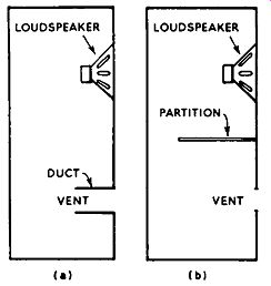
FIG. 5.26. Methods of reducing the en closure resonance; (a) by means
of a duct: (b) by fitting a partition.
If the balance is disturbed in the opposite way, and the response of the lower resonance is of greater amplitude than the upper, the trouble is likely to be caused by either too small an enclosure or too large a vent. In this case the area of the vent can easily be reduced until tests indicate a reasonable match. If the enclosure is much too small, however, the required reduction in area of the vent may promote too great a drop in bass output. This can be overcome either by extending the vent aperture inwards by means of a duct (Fig. 5.26a) or by inserting an acoustically lagged partition between the speaker and vent (Fig. 5.26b). The partition should extend about three quarters of the way into the cabinet and should very snugly join the front and sides. When either of these procedures is adopted, the original vent area can remain, and in consequence there is considerably less loss in bass input.
SPEAKER PLACING
The performance of a speaker system can be greatly affected by its position in the listening room, while the room furnishings are also a governing factor on how the reproduction "sounds" to a listener. A room without heavy furnishings, such as armchairs and carpets, is prone to be very "live"; little sound is absorbed and reflections occur between the walls and hard objects. There is a rising top response and a possibility of "ringing" at certain frequencies. Careful adjustments to the tone controls can often effect a compromise under these conditions, but such adjustments should be made in relation to the placing of the loudspeaker.
Standing waves, which give rise to undesirable acoustics, can be modified in amplitude and frequency simply by moving the speaker system from one point to another. In a room which is subject to standing waves it is often desirable to situate the speaker in one corner, as distinct from having it in the center of a wall. However, the best position can be found only on a trial-and error basis, and it is almost useless to try to formulate any hard-and-fast rules about this. The speaker should be situated where it sounds best and not where it looks best, but, unfortunately, this is not always acceptable to the lady of the house!