ONE major advantage that tape has over the disk is that it is a recording medium which can be exploited with almost equally good results by the amateur enthusiast as well as by the professional recording engineer.
A high-quality disk-recording outfit necessarily costs much more than the average enthusiast can afford, whereas a hi-fi tape recorder complete is little more expensive than, for example, a hi-fi amplifier and loudspeaker system or a television set.
Interest in tape recording is growing rapidly, and its popularity has undoubtedly been boosted by recent developments in stereophonic reproduction; one of its most attractive attributes is the comparative ease with which a library of tape records can be built up by recording radio programs, preferably those broadcast on the VHF-FM system (see the author's "F.M. Radio Servicing Handbook"). The quality of reproduction of a tape record made by this means can be as good as that obtainable from long-playing disk records. Tape records, like disk records, are also available commercially and are made in both single-channel and dual-channel (stereophonic) versions.
Not only music lovers, but amateur dramatic societies, educational authorities, business, science and industry generally are finding more and more uses for tape recording.
Magnetic tape is also used for the recording of television pictures; as with sound, pictures are broken down into component parts to form electrical impulses, and the impulses are recorded on the tape. The pictures are thus "stored" for future use, and can be reproduced whenever required by playing the tape back through the same machine, which then serves to change the impulses back into the original pictures.
There is little doubt that the enthusiast of the future will have available a vision tape player which can be plugged into the video channel of a tele vision receiver for the showing of pre-recorded tapes. Vision tape records, also carrying a sound accompaniment, will be available, and the enthusiast will eventually be able to make his own vision records with the aid of a small television camera and a tape recorder; immediate replay facilities will be available by way of the television screen.
Tape will also store most of the program material to be transmitted over television networks. Hybrid s.h.f. and wired television networks, will be extensively used in the future, and video tape machines will be connected into such networks to facilitate the showing of items of local interest, such as news and advertising, sporting events and even films.
Films, as we know them today, will disappear in favor of magnetic tape, and the cinema industry will tie up closely with the electronics industry; cinemas will close, and every household with a television set will be a potential box office for the new cinema industry. The insertion of a coin into a small box by the side of the television set will bring on to the domestic screen the very latest film through the medium of magnetic tape. We have, in fact, only just begun to exploit the potentialities of tape recording.
THE TAPE RECORDING PROCESS
Magnetic tape is a thin plastic material i in. in width and coated with oxide of iron on one side; this is the "sensitive" side on which the recording is magnetically impressed. With the highly developed processing of modern tapes, it is often difficult to see which side of the tape actually contains the oxide of iron. From both the mechanical and electronic points of view, this is a good thing, because the smoothing of the coated surface as the result of the "buffing" process during manufacture reduces wear on the recording, playback and erase heads and ensures consistent mechanical contact of the tape with the heads, which is desirable for extended high-frequency response.
The recording head magnetizes each section of the tape as it passes over the gap between the poles of the head. The recording head is, in fact, an electromagnet which is energized by the signal current at the output of an amplifier. Thus, if a person is speaking into a microphone connected at the front of the amplifier, the recording head connected to the output is energized by the current which is varying in unison with the sound waves. This means that the magnetic field across the poles of the recording head is also varying both in polarity and in magnitude to the same pattern as the sound waves. It is this varying magnetic field which is used to impress a magnetic pattern on the coating of the tape as it passes over the gap of the recording head.
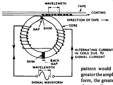
FIG. 9.1. As the recording tape posses steadily over the gap of the
recording head, small magnets ore formed on the coating, the character
of which conforms to the signal waveform.
The idea is illustrated in Fig. 9.1. Here the signal current is represented by a sine wave which causes the polarity of the field across the recording gap to reverse each half-cycle. Thus, as the tape passes steadily over the gap small magnets are formed on the coating of the tape, as shown. The effect would be the same if a more complex signal waveform, such as speech or music, were used, but then the amplitude and the wavelength of the recorded pattern would also be complex. The greater the amplitude of the signal wave form, the greater will be the current in the recording coils and the greater the strength of the magnetic field across the gap. Therefore the strength of the magnets formed on the tape will also be greater.
The actual length of the magnets formed depends upon the wavelength of the signal waveform. Two magnets go to make up one wavelength as the result of the positive and negative half-cycles of the signal waveform (i.e., each half-cycle of signal produces one magnet). The length of the magnets is also governed by the speed at which the tape passes over the gap-the wavelength is equal to the speed of the tape divided by the frequency of the signal current. Thus, at 7.5 in. per second, the wavelength representative of a 7.5 k hz signal is 0.001 in., so the length of each magnet formed on the tape is approximately half this value, or 0.0005 in. This is a very short magnet indeed, but it is even shorter at higher frequencies.
We must now consider the hysteresis loop, sometimes referred to as the cycle of magnetization. When an electromagnet is energized progressively by the building-up of electric current in its winding there is built-up a magnetizing force around the coil or between the pole pieces of the magnet.
This magnetizing force is denoted by the capital letter H, and if a ferrous material (one which is affected by magnetism, such as iron or steel) is brought within range of the field of this force it will have induced into it a magnetic flux; i.e., the material will also be magnetized. Flux is denoted by the capital letter B. It follows that the greater the magnetizing force, the greater will be the flux induced into the material and the stronger will be the magnetic symptom.
This action can be studied in more detail from the so-called hysteresis loop, shown in Fig. 9.2. Here the magnetizing force, both positive and negative, is represented by the horizontal line, while the flux is represented by the vertical line. Let us assume that the ferrous material is in a magnetically ...
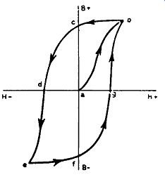
Fig. 9.2. The hysteresis loop.
... neutral condition, and that the force H is increased from zero (point a) in a positive direction. This can be brought about by increasing the current in the electromagnet; if it is increased in the opposite direction, then the value of H will rise negatively.
Thus, as H increases so will the value of B, and will trace the curve ab.
If now the force H is decreased (by decreasing the current in the coil), the value of B will not fall to zero, but line be will be traced and at zero H there will be an appreciable value of B in the material as represented by point c on the B + line. This value of B is representative of the residual magnetism held by the material. In other words, the material has been magnetized by the magnetizing force which was applied.
However, if force H is now increased from zero in a negative direction, the value of B will fall and line cd will be traced. At point d the material is once again in a demagnetized state. The value of H which is required to demagnetize the material is a measure of the coercivity of the material. As H is further increased negatively, the line de is traced, and at e the material is once again magnetized, but in reversed polarity. At point/His again at zero, and then as H is increased positively once again, the remainder of the loop fg and gb is traced. It should be noted that the initial path ah is traced only when a material in a magnetically neutral condition is subjected to force H. From the foregoing, it should be clear how a tape is magnetized by the changing magnetizing force across the gap of the recording head-bearing in mind that the tape is passing the gap all the time.
Whilst the hysteresis loop shows the relationship of the flux induced into a material to the force producing it over a complete cycle, it is not wholly representative of the residual magnetism retained by the material owing to the applied magnetizing force for a number of different loops, working from zero H up to saturation, both in positive and negative values. (Saturation indicates the point where an increase in H does not result in an increase in B.) The residual magnetism retained by a material (usually referred to as remanent induction and still denoted by B or sometimes Br) and the magnetizing force H required to produce it are plotted to form a transfer characteristic or remanence curve. Such a curve is shown in Fig. 9.3, from which will be seen that the remanent induction or intensity of magnetism impressed upon...
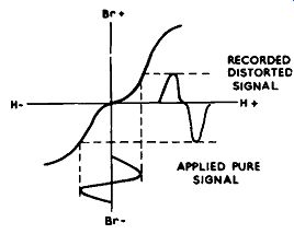
Fig. 9.3. The transfer characteristic of the remanence curve, showing
how the kink in the curve distorts the recorded signal.
... the tape will not be proportional to the force H or the current in the recording head owing to the pronounced curvature of the characteristic.
This "transfer distortion" can be avoided by applying a bias in the form of a high-frequency sine wave to the recording head along with the actual signal. The frequency of the bias is usually in the region of 30-100 k hz, and therefore in the supersonic region and outside the range of hearing. The bias signal is superimposed on the signal to be recorded and has the effect of combating the kink in the center of the transfer characteristic. How this happens is somewhat complex, and there are several theories on the matter.
However, a working knowledge can be obtained from Fig. 9.4, which shows the applied signal on which is superimposed the bias signal, and the resulting distortion-free recorded signal. It appears that the applied signal is alternated either side of the transfer characteristic because of the bias, and that an exact replica of the applied signal is impressed in magnetic form upon the tape as the result of an average of the remanent induction being "sampled" over the two branches of the characteristic curve.
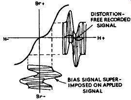
FIG. 9.4. Showing how the application of a high-frequency bias on the
applied signal has the effect of combating the kink in the center of
the transfer curve and gives a distortion-free recorded signal.
PLAYBACK
Having recorded a magnetic pattern on the tape as described, it is a simple matter to re-convert the pattern back to electrical signals which can be amplified and fed to a loudspeaker system, by passing the tape over a replay head. The replay head is virtually the same as the recording head, and in most portable-type recorders the one head serves for both recording and playback; the tape speed must be the same for both recording and playback if distortion is to be avoided.
As the tape passes over the replay head the magnetic pattern produces corresponding variations of flux in the core, which in turn induces e.m.f. variations in the windings matching the pattern of the original signal; these variations in e.m.f. are applied to the grid of an amplifier, in the same way as are the variations of e.m.f. produced by a pick-up or microphone.
The gap between the pole pieces of the replay head has a considerable bearing on the response of the head to high frequencies, and in order to secure optimum output voltage at high frequencies the length of the magnets impressed upon the tape should not be much smaller than the size of the gap.
We have seen that two magnets represent one wavelength and that the speed of the tape past the head as well as the frequency of the signal governs the length of the recorded magnets. For example, if the tape speed is 7.5 in. per second and the frequency of the recorded signal is 7,500 hz, the wavelength of the recorded signal will be 1/1000 in. (0.001 in.). This means that the length of each recorded magnet is half this value, which is 0.0005 in. From theoretical considerations, therefore, it would seem that in order to secure optimum response at 7,500 hz the gap size should be 0.0005 in.
In practice this is not strictly true, because there are other factors involved. One is that the magnetic field across the gap due to the magnetized tape tends to bulge outwards and cover a greater distance than that represented by the gap itself. This effect is known as "fringing", and tends to reduce the high-frequency response for a gap size as computed above. The effect is more apparent, and loss in high-frequency response becomes very marked, if the tape is not making intimate contact with the head pole pieces.
Generally speaking, the maximum output with a gap size of 0.0005 in. occurs in the region of 4-5 k hz at a tape speed of 7.5 in. per second. This is not the highest frequency which can be reproduced, however, since as the frequency is increased above that representing optimum output, the output does not suddenly fall to zero but falls off over several octaves, and when the gap size is equal to the wavelength of the recorded signal (i.e., two magnets in the gap) the output falls to zero owing to flux cancellation in the head.
At frequencies below that representing optimum output the output falls at the rate of about 6 db per octave.
As a means of securing an improved high-frequency response, without too great a tape speed, manufacturers are investigating the problems involved in producing heads with very small gaps. Not so long ago, a gap size of 0.0005 in. was considered to be about the practical minimum. These days, however, gaps smaller than 0.0002 in. are becoming commonplace. The BBC's Vision Electronic Recording Apparatus (VERA) uses heads with gaps of the order of 0.00002 in., and at a tape speed of 200 in. per second there is only a 3 db fall in response at a frequency of 2.5 M hz. As a rough guide, the effective gap size should be approximately 0.5 of the shortest half wavelength to be reproduced.
Mumetal, Permalloy and other high-permeability alloys are used for the head pole pieces, and the gap is closed by a non-magnetic shim as a means of keeping it clear of magnetic coating from the tape and of concentrating the flux towards the tape. An additional gap is usually introduced diametrically opposite the functional gap, whose purpose is to maintain a linear relationship between the recording current and the flux at the gap. The rear gap is also closed with a non-magnetic shim, and has a width approximately ten times that of the functional gap.
It has already been mentioned that a common head is usually employed for both recording and replay. Where a separate recording head is used, however, the gap size is not so important as that on the replay head. Since the recording does not occur until the tape section reaches the end of the gap, a gap size of the order of 0.0001 -0.0015 in. is adequate.
ERASURE
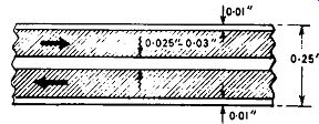
Fig. 9.5. Dimensions of tape and tracks.
One of the most attractive features of tape recording is that the material recorded can be erased from the tape if it is not suitable or no longer required, and the tape can be used over and over again almost indefinitely. The problem is simply that of demagnetizing the tape. This is best done by passing the tape through a strong alternating field; the field is produced across the gap of an erase head and the winding is energized from the high-frequency oscillator supplying the bias current. The construction of the erase head is slightly different from that of the recording or replay head. The core material has a higher saturation value, and a fairly wide gap in the region of 0.015 in. is usually adopted. Some erase heads have twin gaps, or two separate erase heads may be employed, as a means of ensuring complete erasure.
For successful erasure a high value of alternating current in the erase head winding is necessary, and in order to help satisfy this condition the head is often arranged to resonate at the frequency of the applied signal.
At one time home recorders employed a small permanent magnet to erase an un-required recording by magnetizing the tape fully in one direction only. Although this simple method, by which the magnet is brought into contact with the tape before it is presented to the recording head, does result in complete elimination of the recording, distortion and a poor signal-to-noise ratio are inevitable when the tape is next brought into service, owing to the standing magnetism on the tape.
There are devices available which are capable of bulk erasure of a tape.
The whole tape is set up on the instrument, and the tape is subjected to a very strong magnetic field for several seconds or more, while the spool is rotated on a spindle. This is a very rapid and efficient method of erasure, is convenient when it is required to remove a recording before the tape is re-issued, and also ensures a very desirable high signal-to-noise ratio. A bulk erasure device of this kind is marketed by Leevers-Rich Equipment, Ltd.
RECORDING TRACKS
In early models of home tape recorders almost the full width of the tape was subjected to the recording flux and magnetized. This arrangement is still adopted in professional equipment and machines employed for disk-dubbing because of the ease of editing and the slightly improved quality obtained by using the full width of the tape. With modern domestic tape recorders, however, dual-track facilities are incorporated. Two separate recordings can therefore be impressed side by side on one tape. The track dimensions for this method are given in Fig. 9.5. Whilst these dimensions are almost standardized, one or two very slight deviations are sometimes found, but these have little or no adverse effect on the interchangeability of recorded tapes, provided the direction of scanning of the tracks is as indicated by the arrows in Fig. 9.5, that is with the coated side of the tape away from the observer.
Some machines employ two recording/replay heads, one for each track, and the mechanism is arranged so that a button or switch changes from one track to the other, whilst also reversing the direction of the tape travel. The Simon Model SP4 tape recorder incorporates automatic tape reversal fo, continuous recording or replay, without button-pressing or transposition of spools. When one track runs out, the tape automatically reverses and the other track is switched in.
With machines having a single recording/replay head, track change is accomplished by reversing the spools and turning them over, so that the unrecorded bottom half of the tape is scanned by the head.
TAPE DECKS
Generally speaking, the tape deck is a complete unit in itself, as a record player is a complete unit in relation to a radiogram. There are one or two variations in this respect, however, particularly with Continental equipment, where the tape mechanism is an integral part of the recorder. Several makes of British recorder have decks made by organizations specializing in this field, such as Collaro, Truvox and Wearite. The recorders show many variations in the style of cabinet, facilities provided, design of amplifier, type of loudspeaker used, etc. However, to give some idea of the principles ...
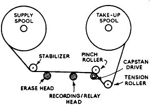
Fig. 9.6. General layout of tape deck.
... involved, the layout of a typical tape deck is illustrated in Fig. 9.6.
The tape deck must arrange for a constant drive of the tape past the various heads, whilst maintaining control of the tape on the spools. The actual drive is obtained by means of a very accurately machined capstan which is driven at a constant speed against a pinch roller, the tape being pressed between the two, as shown. The capstan is either driven by the motor through a friction coupling or, in less elaborate machines, is mounted direct on to the spindle of the motor. Whatever the method adopted, a weighty flywheel is always employed on the capstan shaft to reduce any irregularity in the bearings or motor, and thus assist in maintaining constant speed.
In some cases the tape speed is controlled by interchangeable capstans.
This is the case in the Truvox deck, where speeds of 3¾ in. per second and 7½ in. per second are available. The slow speed gives a playing time of 60 minutes per track for standard tape and 90 minutes per track for long playing tape, while the playing time is reduced by 50 percent at 7.5 in. per second. (That is for 7.5 in. diameter spools containing 1,200 ft. of standard tape and 1,800 ft. of long playing tape, which is thinner than the standard.) Various other arrangements are in use for speed change, including stepped drive wheels, of similar arrangement to those incorporated in record players, and control by switching the field windings in the motor (Grundig, for example). Apart from the two speeds mentioned above, a speed of 15 in. per second is also available on some models as a means of securing a really first-class high-frequency response. A speed of 1.875 in. per second is some times used for the recording of material where quality of reproduction is not a prime factor.
Whilst the tape is being driven past the heads the tape take-up spool is slightly under load-sometimes through a mechanical or electromagnetic clutch-to ensure that the recorded (or reproduced) tape is adequately controlled. In some cases, the supply spool is also loaded lightly to avoid spilling of the tape from the spool due to overdrive.
Facilities are available for fast rewind or wind-on. A separate motor or motors are sometimes used in the more expensive equipment, while very successful results are possible by employing for these functions the capstan drive motor. The Truvox deck can re-spool a 1,200 ft. reel of tape in less than
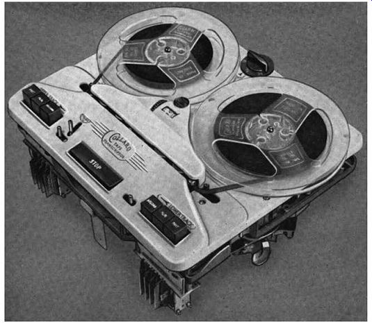
FIG. 9.7. Collaro Mk. iii tape transcriptor.
one minute, using three B.T.H. shaded-pole motors. Two motors are embodied in the Collaro deck, while the Grundig works very successfully with one motor.
There are other refinements, and various combinations of switching and mechanical functions, which need not be described here. It is now becoming common practice to incorporate such things as "pause control" (for stopping the transit of the tape past the heads and applying the breaks to the spools whilst leaving all the switches and their mechanical functions in the selected positions), "playing time indicator" (facilitating the location of any recorded passage), and "instant track change", as already described.
The well-known Collaro Mk. III tape transcriptor is illustrated in Fig. 9.7, while the extensively used Truvox Mk. IV tape deck is shown in Fig. 9.8. Note the three digit counters on both decks, which serve admirably as place locators. The Collaro deck has facilities for instantaneous changes of track, while the same facility is available on the Truvox deck by spool transposition,...
FREQUENCY RESPONSE
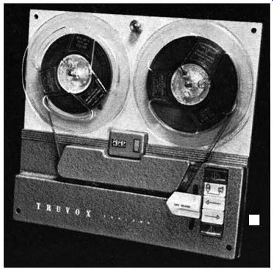
FIG. 9.8. The Truvox Mk. IV tape deck with place locator.
If a tape record is made with an amplifier possessing a flat response, and it is also replayed on a linear amplifier, the frequency / output curve of the recording will be similar to that shown in Fig. 9.9 (a). Up to the point of maximum response, the output rises steadily at the rate of about 6 db per octave. This is because the voltage across the recording head, which is essentially an inductive element fed through a resistor to provide a recording current which is constant irrespective of frequency, doubles every time the frequency is doubled.
Towards the peak of the response, however, the rate of rise tails off slightly, and beyond maximum response it falls fairly quickly. This deviation from the "natural" 6 db per octave rise is promoted by high-frequency losses inherent in the system generally. For example, there is the effect of the gap, the speed of the tape past the head, the coercivity of the tape and capacitive losses in the amplifier proper. Also, the very short magnets which correspond to high recorded frequencies tend to demagnetize themselves, though high coercivity tape is less prone to this trouble. A reduction of high-frequency loss owing to this cause of some 8 db may be expected by the use of a good quality high-coercivity tape (it will be remembered that coercivity is a measure of the ability of the tape to resist demagnetization).
It will be clear that the response relative to frequency is governed by the speed at which the tape passes the heads. The curve given in Fig. 9.9 (a) is for a speed of 7½ in. per second. From this curve clearly emerges the fact that some form of equalization is called for on replay. In practice, equalization is applied during the recording process as well as during replay. Whilst recording, the recording head is invariably fed through a filter which provides a treble lift as a means of combating some of the high-frequency losses. This filter may be either a tuned device, including an inductance, or a relatively simple resistance-capacitance network.
On replay there is a circuit which gives a rise in bass response and a further circuit which gives a high-frequency lift to provide additional compensation for losses in the replay head. Fortunately, there is some standardization with regard to recording and reproducing characteristics. These are dealt with in British Standard 2478:1954, which accepts the recommendations of the Comite Consultat International des Radio-communications (C.C.I.R.) for program interchange on tape. For tape speeds of 15 in. per second and 30 in. per second, the specified frequency-response curve represents a bass rise equivalent to that secured by a series-connected resistor and capacitor having a time-constant of 35 microseconds. For a tape speed of 7.5 in. per second a time-constant of 100 microseconds is recommended.
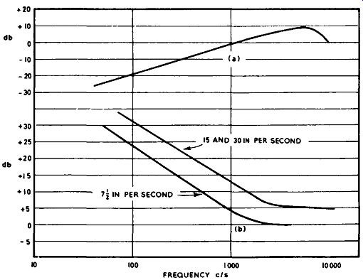
FIG. 9.9. Frequency characteristics of tape recording.
FIG. 9.10. Circuit diagram of the Truvox Type K tape-recorder amplifier.
The curves obtained by these time-constants, assuming an "ideal" reproducing head, are shown in Fig. 9.9 (b). In practice, these time-constants may have to be altered slightly to suit the particular head in use. It is usually necessary to consider the equalized pre-amplifier and reproducing head as a complete unit with regard to shaping the overall response. All tape records, including "Stereosonic" versions, are recorded to suit the C.C.I.R. characteristics, so it is as well for the recorder to maintain this replay response within the tolerance of plus and minus 3 db, at least.
AMPLIFIERS
Fig. 9-10 shows the circuit of the Truvox Type K tape-recorder amplifier which, apart from being used in certain Truvox tape recorders, can be obtained as a separate unit if an enthusiast requires to make up his own recorder, or if it is required to add another channel for the playing of "Stereosonic" tape records.
It should first be noted that the various switches, representing record/ replay, are shown in the "record" position. The first stage, VI, serves on the "record" position as a high-gain microphone amplifier. The microphone signal is applied to the control grid of the valve, which is a low-noise pentode, by way of jack 1. It will be noted that this is a high-impedance input and suitable for a crystal microphone or an electromagnetic type embodying an impedance-matching transformer.
The amplified signal is fed to the grid of V2A (half of Mullard ECC83) through the 0.05-mF coupling capacitor and 330k resistor. The resistor capacitor network between the anode and grid of V2A forms a parallel-T feedback system which, being frequency-selective, gives a top lift to compensate for high-frequency losses, as already described. The frequency compensated output from V2A is passed by way of the volume control-the tone control being out of circuit on "record"-to a further amplifier V28 (the other section of the ECC83). This section also functions as the recording output valve, the signal being fed through switch D, through a further resistor-capacitor network for additional head compensation, to the record/ replay head through switch A. The signal at the anode of V28 is also applied to a rectifier WX6, and the d.c. voltage developed across the 4.7-megohm load resistor is applied to the recording-level indicator valve V3, being brought into operation by switch B. During the recording process, valve V4 (EL84) serves as the high frequency oscillator. L1 is the oscillator coil, which is resonated by the parallel 0.002-mF capacitor. Switch I brings the oscillator into circuit by completing the coupling between the grid and the anode. It will be seen that the oscillator voltage is taken from the anode of the valve and is fed through a capacitor of 100 pF to the recording/replay head by way of switch A. The erase head is also energized by the oscillator current through the 0.01-mF coupling capacitor and switch J. The bias voltage is fixed at 48 k hz, and the level of the signal is of the order of 150 volts at the erase head and 80 volts at the recording head. Both heads are of the high-impedance type and thus match directly into the circuits without transformers.
The amplifier is powered by means of a full-wave h.t. rectifier valve, V5 (5Y3). The mains transformer carries two l.t. windings, one for the heaters of the valves and the other for the heater of the rectifier. Although there is no smoothing choke, a remarkably low level of hum (45 db down at 4 watts) is achieved by the use of four 40-mF electrolytic capacitors and associated filter resistors.
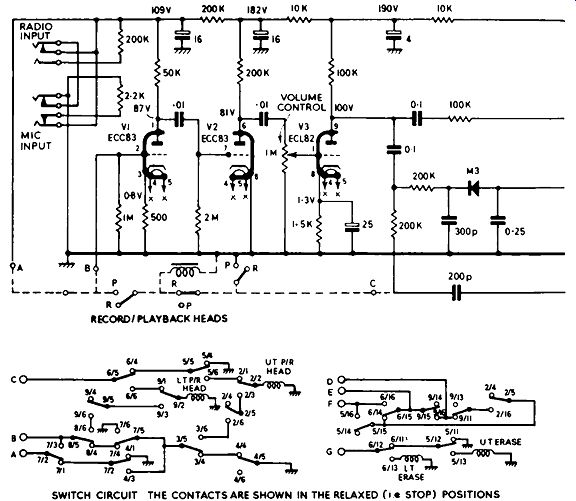
FIG. 9.11. Circuit diagram of the Sound Sales A20 tape recorder. Connections
shown as dotted lines in the circuit diagram are simplifications of switch
connections, the true connections being given in the lower diagram.
The "record/replay" switch is actuated by a relay whose winding--denoted R/P switch solenoid on the diagram-is energized by the instantaneous shorting together of the two wires labeled "brake" on the diagram.
This action trips the relay switch so that it returns to the "replay" position.
It is necessary to re-set the switch to the "record" position by pressing the appropriate button on the amplifier control panel.
On the "replay" position the record/replay head is switched into the grid circuit of V1, which now acts as the reproducing-head amplifier, by the changing-over of switches F and A. Switch C alters the coupling response so as to give a further lift of treble, switch H brings in the tone control and removes the 0.01--mF capacitor from across the cathode resistor of V2B. The oscillator is switched off by switch I and switch D disconnects the head equalizer and couples the signal at the anode of V2B to the control grid of V4 (V4 now acts as the sound output valve). Switch B disconnects the level indicator valve, switch E brings in the output transformer and switch J short-circuits the erase head which, of course, is not required on replay.
It will be seen that negative-voltage feedback is applied over two stages from the output transformer to the cathode of V2B. Since the 0·01--mF capacitor is disconnected from across the cathode resistor, the feedback is not frequency-selective as it would be if the capacitor was left in circuit.
The output transformer provides for loudspeakers of either 3 ohms or 15 ohms impedance. The signal outlet at che anode of V2A by way of jack 3 permits monitoring of the recording or recorded signal. If required, the signal at this point can be applied to the input circuits of a separate hi-fi amplifier.
The signal level at this point is approximately 0.5 volt at 500 ohms impedance.
Whilst it will usually be found necessary to employ V1 as the microphone amplifier during the recording process, the sensitivity at jack 1 being in the region of 1-2 m V, a higher signal level should be applied by way of jack 2, where the sensitivity is something like 500 m V; for example, a gramophone pick-up signal or a radio signal can be introduced here. The Truvox radio jack is useful for the recording of radio programs, but this should be inserted into jack I owing to the low output signal from the crystal detector.
SOUND TYPE A20 TAPE RECORDER
The circuit diagram in Fig. 9.11 of this recorder shows that it has much in common with the Truvox circuit. Instead of a low-noise pentode, however, two cascade-connected triodes VI and V2 (Mullard ECC83) provide the necessary high gain for use as a microphone amplifier during recording and a replay-head amplifier during replay, these functions being governed by the setting of the changeover switches, as before.
The ECL80 valve is arranged so that the triode serves as recording amplifier and the pentode as oscillator during the recording process, and as voltage amplifier and output valve respectively during replay. The EM8l acts as a recording-level indicator, the controlling signal being obtained from the recording signal (in the anode of V3) and rectified by the metal rectifier M3. There are two inputs, but these operate in the grid circuit of the first triode.
ADDING A TAPE DECK
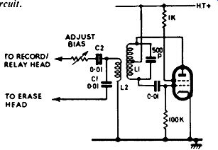
FIG. 9.12. Typical bias oscillator circuit.
Many enthusiasts, already in possession of a good hi-fi amplifier, may wish to add a tape deck without going to the expense of purchasing a complete tape recorder. This can be done fairly easily by utilizing the existing amplifier. However, it is not usually possible to connect the replay head direct to one of the inputs of the amplifier, even though one may be marked "tape input", owing to the lack of gain and need for special equalization.
From the replay point of view, an equalized-head amplifier is required, whose equalization response can be switched to suit the various tape speeds in accordance with the C.C.I.R. characteristics.
A single low-noise pentode, such as the Mullard EF86, can usually be arranged to provide sufficient rise of signal from the replay head to drive a control unit of most makes. The stage will incorporate an equalizing network, preferably of the selective-feedback type already dealt with. Special attention should be given to the layout of the components and to the common-negative connections on the chassis, so as to avoid circulating earth cur rents which become manifested as hum from the loudspeaker.
The precise characteristics of the equalization will depend to a large degree on the type of head adopted, but manufacturers of tape decks and heads invariably issue a suitable circuit. Such an arrangement will permit the reproduction of tape records, but if a facility for recording is required as well, a recording amplifier and oscillator will also be necessary.
The reproducing-head amplifier can serve as the microphone amplifier for recording. This will have sufficient gain, since the output from an average reproducing head is little more than 1-3 mV, which is more or less the same as the output from a microphone.
A recording current of the order of 100 microamps is usually required and this can be obtained with little trouble from a simple triode stage, which may be fed from the microphone amplifier. It will be necessary to have provision on the amplifier to switch out the bass-lift equalizing and to intro duce a form of pre-emphasis. Alternatively, the amplifier can be switched to have a linear response, and the pre-emphasis introduced in the network from the recording output valve to the recording head. Additional pre-emphasis can, if required, be introduced between the coupling from the microphone amplifier and the recording output valve; this can take the form of a parallel-T network.
The considerable amount of high-frequency power required for efficient erasing can only be obtained from a fairly large power pentode or tetrode, such as the 6V6 or EL84. Oscillators in general use employ either the series fed Hartley or the Colpitts circuit. A typical Hartley circuit is given in Fig. 9.12. Here L1 is the tapped oscillator winding, which i!- tuned within the frequency range of 30-80 k hz by the 500-pF shunt capacitor. L2 is the coupling coil which feeds the oscillator current into the erase head through C1 and into the record/replay head through C2 and R1. R1 is variable so that the optimum value of high-frequency bias can be selected for the type of tape and the signal voltage employed.
For the purpose of erase the value of the bias in the erase head is not critical, provided that the bias current is sufficient to secure complete erasure.
The current in the recording head is, however, much more critical. As the bias current is increased so the response falls, but as the recording current is increased so a greater level of bias current is required to alleviate distortion.
It is usually necessary to perform a series of tests in order to establish the best setting for the bias level control. The aim should be to achieve best signal-to-noise ratio consistent with the minimum of distortion and the best high-frequency response.
A distorted bias signal will tend to impair the signal-to-noise ratio to a large degree. The, bias oscillator should be capable of producing a pure sine wave at full output, and to assist in this respect professional equipment often uses a push-pull oscillator circuit.
SERVICING TAPE EQUIPMENT
Faults likely to develop in tape recorders are of two distinct types: there are mechanical faults relating to the tape deck proper, and electrical faults associated with the amplifiers, oscillator and various equalizing networks.
Faults of amplifiers-particularly those resulting in complete failure of recording, reproducing or both-can be located with reasonable ease by adopting the techniques described in Section 4.
It helps considerably if a circuit diagram of the defective instrument is available, for then a study of the various stages will reveal the valves and components which are common to both recording and reproducing, and if the cause of failure of both services is being sought the components most likely to be responsible can be examined in more detail.
For example, failure of VS in Fig. 9.11 will affect both recording and reproducing, since this valve serves both as sound output on replay and bias oscillator on record. The replay section will be totally dead, assuming that VS has failed completely, but on the "record" position the signal-level indicator will function normally. This may lead to a suspicion of trouble in the sound amplifier or associated networks. If a trial on another machine of the tape that has supposedly been recorded results in severe distortion owing to the lack of recording bias, the diagnosis will be proved accurate. In practice, it is usually the faults of a more subtle nature which cause difficulty, and these can be of both electrical and mechanical origin.
A poor high-frequency response, particularly from tapes recorded on another machine or from a tape record, is often caused by maladjustment of the recording/replay head. It is essential that the angle that the gap of the head makes with the direction of motion of the tape is the same both on record and replay. Whilst this angle will obviously remain consistent when the tape is recorded and reproduced on the same machine, it is desirable to know that a recording is going to be satisfactory when played on a different machine.
For this reason the head is best adjusted for optimum high-frequency response with a standard test tape or a tape record having plenty of "top". Test records giving a tone of 10 k hz or 12 k hz are available for this purpose.
The azimuth adjusting screw in proximity to the head or head securing bracket should be slowly turned first one way and then the other whilst the output from the test tape is being observed on an output meter or a.c. voltmeter.
The point giving maximum output should be selected.
If the recording/replay head becomes slightly magnetized a marked increase in background "hiss" on replay results. Theoretically, the head should not become magnetized since a large-value time-constant is used in the h.t. feed to the oscillator valve which causes a gradual decay of oscillator current in the heads, and thus avoids surges which are likely to magnetize the heads. However, in practice small current surges occur which promote the trouble; there is also the possibility of the heads coming into contact with a magnetized screwdriver or a magnetic field. Again, there is the possibility that the head may be checked for continuity with an ohmmeter.
Whatever the cause, it is necessary to demagnetize the head to reduce the "hiss" and to prevent a constant flux being impressed upon the tape. The best way of securing this is by the use of a "de-fluxer". An ideal instrument of this kind is the Wearite Defluxer (Fig. 9.13). This has a special shaped pole piece which can easily be brought into contact with the head pole pieces.
The instrument is mains operated, and at the end removed from the pole piece is a press-button control switch.
In operation, the pole piece is brought into contact with the head and the button depressed. The pole piece is then gradually taken away from the head, but the button should not be released until the head is outside the influence of the field. In this way complete removal of residual magnetism is achieved. The instrument is also useful for removing residual magnetism from tape guides, pulleys, etc., which may fall in the path of the tape.
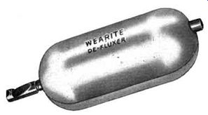
FIG. 9.13. The Wearite defluxer.
If the tape is not making close contact with the head pole pieces, the effect is the same as an increase in the size of the gap, and a loss of the higher frequencies results. If this trouble is suspected, the heads should be examined for wear, and if very badly worn should be replaced. All traces of accumulated particles of oxide coating from the tape should be very carefully removed from the head pole pieces. A soft brush can be of considerable assistance in this, but cleaning fluid should not be used unless specifically indicated in the manufacturer's instructions. The tape guides and pulleys should be examined for adjustment to ensure that the tape is being evenly transported past the heads.
Excessive wow should lead to checking the pressure between the capstan and the pressure roller, drag on the spools due to an incorrect clutch adjustment, the regularity of the various drive faces (particularly the rubber rollers and jockey pulleys), the lubrication of the bearings and the alignment of the flywheel and motor spindle. Worn rubber or composition friction drives and oil on the surfaces of the drives are common causes of the trouble, especially of the lower-frequency wow. Flutter, at a higher frequency, may also be caused by an eccentric drive wheel, or by "snatching" of the tape owing to irregular binding of the supply-spool bearing.
If a double-beam oscilloscope, an audio oscillator and a 1,000- hz test tape are available a useful test for wow can be made. The test tape should be played on the recorder and the output signal monitored on one beam. The other beam should be connected to the audio oscillator, which should be adjusted for 1,000 hz. Adjustments should be made to the controls of the oscillator and oscilloscope until the two waveforms occur approximately in step. Wow in the recorder will cause a regular movement back and forth of the waveform from the recorder, while the waveform from the oscillator will remain constant. The amount of shift relative to the stationary trace can easily be observed and the percentage in speed variation ascertained. For example, a shift of 1 hz represents a wow content of 0.1 percent.
RECORDING FROM RADIO
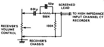
Fig.
9.14. Method of extracting a high-impedance low-level signal from a receiver.
(Not useable for a.c./d.c. receivers, or where the chassis is connected
to one side of the mains supply.)
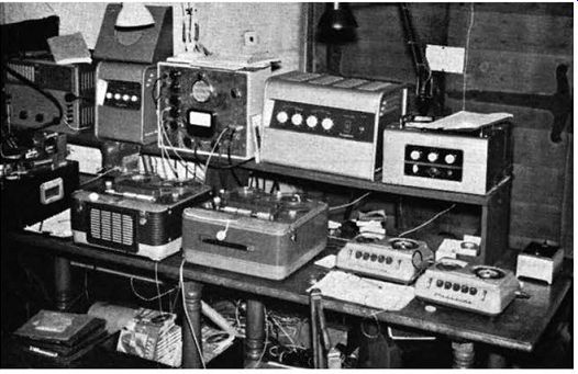
Fig. 9.15. Tape recorders and sound equipment installed for use at the
Duke of Edinburgh's Study Conference at Rhodes House, Oxford (1956).
It will often be required to make a recording from a radio signal. One way of doing this is to simply stand the recorder's microphone in front of the receiver's loudspeaker. This is not a desirable method owing to the introduction of distortion from the receiver's output stage and loudspeaker; the recording will also be colored by the acoustics of the room.
Another method is to connect an input channel on the recorder to the extension-loudspeaker sockets on the receiver. This also is undesirable because the distortion in the receiver's output stage will be recorded. By far the best method is to take a connection from the detector circuit of the receiver and feed the signal at this point into an input channel on the recorder. The idea is shown in circuit form in Fig. 9.14.
To conclude this section a photograph is reproduced of a galaxy of tape recorders and sound equipment (Fig. 9.15) which was employed at the Duke of Edinburgh's Study Conference at Rhodes House, Oxford, in 1956. This shows two Grundig Stenorette recorder dictating machines-a Grundig TK820 and a Grundig TK819, both being high-quality home recorders-two Pamphonic amplifiers, a B.S.R. amplifier, a Trix amplifier, an M.S.S. disk recorder, a bulk tape erasure, and sundry other items of equipment. In the center, on the upper shelf, will be seen a microphone mixer unit which was designed by the author to control the various signal inputs from the conference microphones and BBC sound channels.
Tape recordings of every word of the conference were produced and facilities were available for the immediate production of disk recordings from the master tapes-which in overall length represented some 20 miles! The Stenorette dictation recorders aided with the transcription of all the principal speeches. All these facilities were provided by the Electronics Division of Lowe and Oliver, Ltd., of Oxford, to whom the author is indebted for permission to publish this photograph and also Fig. 5.24.