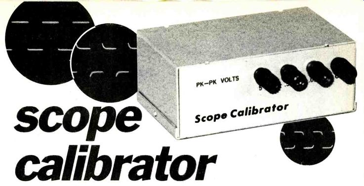
Here are three square wave reference voltages that can also serve as the calibration test signal for your oscilloscope's low-capacity input probe!
by H. DAVID HERMAN
A LABORATORY OSCILLOSCOPE WITH ALL THE BELLS AND Whistles is probably high on the wish list of every electronics hobbyist and experimenter. Unfortunately, they don't come cheap, and many of us must make do with a general-purpose scope from the old days.
But even if your scope is the original Heathkit 0-1, with a variable vertical sensitivity, there's no reason you can't enjoy the modern advantages of a calibrated input sensitivity and a properly adjusted low-capacity probe. All you need is a pro-type oscilloscope calibrator, such as you might find in the latest lab scopes...and you can build just such a device-mostly with parts from your junkbox.
Virtually every modern scope with a calibrated input also includes a calibrator, a square-wave signal output of known, precise-voltage amplitude. To check the calibration of the scope's input, the user touches the test probe to the calibrator test point or output jack. If the CRT doesn't display the correct reading, the user simply tweaks the vertical-gain adjustment until the CRT display is correct.
For example, assume that the oscilloscope calibrator's output is a 400-mV peak-to-peak square-wave signal. If the vertical input is set to 100-mV per vertical division, the display height should be precisely four divisions (100-mV x 4 = 400-mV peak-to-peak). If the CRT display isn't precisely four divisions, the user can adjust the variable-gain control on the scope (if there is one), or the vertical-calibration adjustment until the display height is correct.
From then on, the CRT vertical graticule is precisely calibrated. If the user switches to the x 10 range, each division would represent four volts, and so on for each setting of the vertical-input sensitivity-selector range.
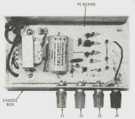
-------- THE ASSEMBLED PRINTED-CIRCUIT BOARD just fits inside the specified
aluminum chassis box. The connecting wires between the printed-circuit board
and the output terminals, J1-J4, are soldered to the foils before the board
is installed in the cabinet, and later they are trimmed.
-------------
PARTS LIST FOR SCOPE CALIBRATOR
SEMICONDUCTORS
BR1-Integrated silicon bridge rectifier, 25 PIV or higher; same as Radio Shack 276-1161
D1-5.1-V Zener diode; see text
Q1, Q2, Q3--2N3391 NPN transistor
RESISTORS
All resistors are 1/2-watt, 5%
R1, R3, R7--100.000-ohm
R2, R4--33,000-ohm
R5--1000-ohm
R6--1500 ohm
R8--910-ohm
R10--10-ohm
CAPACITORS
C1, C2--.01-µF ceramic
C3--.1-µF ceramic
C4--500-uF, 25-WVDC electrolytic
ADDITIONAL PARTS AND MATERIALS
J1, J2, J3--Insulated multi-way binding post, red
J4--Insulated multi-way binding post, black (discard fiber washers and mount directly to metal chassis)
P1--AC-power 3-prong plug with power cable attached
Aluminum 3 x 2 1/8 x 5 1/4-in. chassis box (LMB type), Printed-circuit board materials, hardware, 1-in, spacers, wire, etc.
-------------
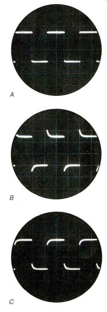
FIG. 1--THE TOP AND BOTTOM EDGES of the Scope Calibrator's output (A) are
flat, and this is how it should appear on the oscilloscope's CRT when fed
through a properly adjusted low-capacity probe. If the oscilloscope probe's
capacity is set too low, the leading edge of the waveform will overshoot
(B), producing a picket-fence type of CRT display. If the oscilloscope probe's
capacity is set too high (C), the high frequencies will be attenuated, producing
a rounding of the trace's leading edge.
If your oscilloscope is a basic model, with only a continuously variable-gain adjustment, oscilloscope calibration can be somewhat difficult if the calibrator has only one output voltage. That problem is avoided by the Scope Calibrator shown in the photographs because it has three outputs: 0.05, 0.5, and 5.0-volts peak-to-peak. Also, instead of a 60- or 120-Hz test frequency, the calibration frequency is the professional value of approximately 1000 Hz, which permits precise adjustment of low-capacity test probes.
To explain. Low-capacity probes must be adjusted to match the specific scope with which they're used. Generally, that is done in the lower-cost probes by adjusting a small trimmer capacitor for a perfectly "square" CRT display. In the more expensive probes, such as those from Tektronix, the barrel of the probe itself is the capacitor adjustment, and is rotated for optimum squarewave form. A properly adjusted probe will produce the CRT display shown in A of Fig. 1, the actual output of the Scope Calibrator project.
If the probe's capacity is set too low there will be an overshoot of the leading edge of the waveform, as illustrated in B of Fig. 1. If the probe's capacity is set too high, it will attenuate the high frequencies, illustrated in C of Fig. 1 by a rounding of the squarewave signal's leading edge.
While it's possible to get in the ballpark with a 60- or 120-Hz squarewave calibration signal derived from the powerline, more convenient and precise adjustment is attained from a 1000-Hz waveform, the usual calibration frequency of lab-grade scopes. The output frequency of the Scope Calibrator shown in the schematic diagram and photos is 1000 Hz.
How accurate
The project is intended to be primarily a junkbox special, and most component parts typically found lying around will be close to the specified output values. For example, the 5-volt output will actually be nominally 4.8 volts. If you adjust the scope's sensitivity so that the outer edges of the trace is 5-volts peak-to-peak, the graticule will be accurate. If you split the graticule lines with the trace you will actually be calibrating to 4.8 or 4.9 volts, depending on the particular transistors used. If you want a precise 5 volts from the center of the trace, substitute two series-connected Zener diodes totaling 5.3 volts for the specified diode, D1 (see Fig.2).
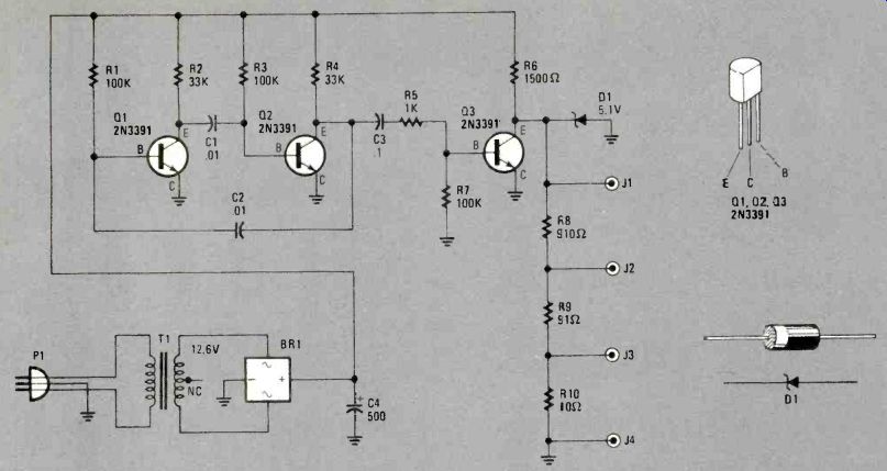
FIG. 2--THE THREE-TRANSISTOR CIRCUIT for the Scope Calibrator consists of
a free-running multivibrator stage, Q1-W2, and a buffer stage, Q3, R8, R9,
and R10 are specified as 5% resistors which are sufficient for this circuit.
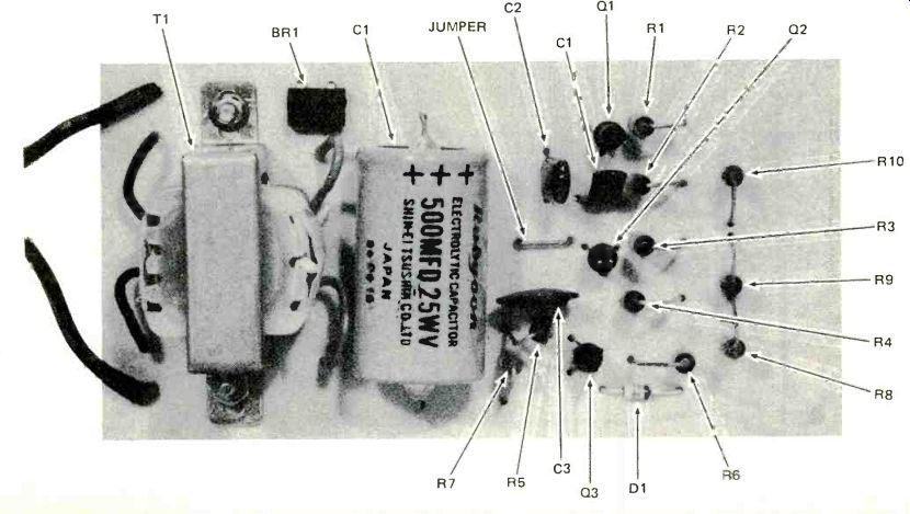
----- THE SCOPE CALIBRATOR'S CIRCUIT is assembled on a printed-circuit
board for which a same-size template is provided. Note that even power transformer
T1 is mounted on the board.
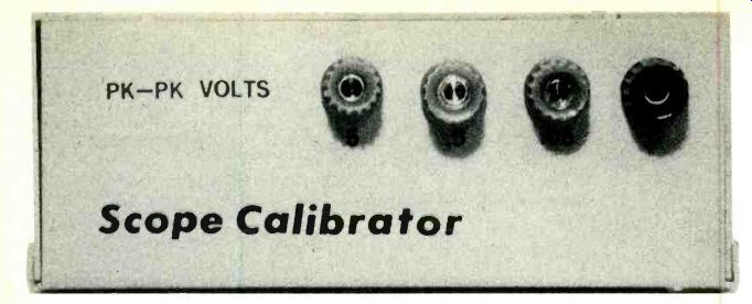
----- THE BUSINESS END of the completed Scope Calibrator. It's only necessary
to touch the scope's probe to the test terminal when calibrating the vertical
input; hence any kind of terminal can be substituted for the multi-way binding
posts, J1 J3.
Construction
The project shown is built primarily on a printed-circuit board measuring 2-1/2 X 4-7/8- inches, which just fits nicely inside a 3 x 2-1 /8 x 5-1/4-inch aluminum LMB cabinet. If the printed- circuit board is larger than the template edges, it will interfere with the installation of the cabinet's cover. The Scope Calibrator's test-voltage outputs are wired to binding posts, J1-J4 (see Fig. 2). Since you're only going to touch the scope's test probe to the calibration voltage, use the least expensive parts-whatever you have lying around. Feel free to substitute pin jacks, banana jacks, or whatever.
Power transformer T1 is rated 12.6 volts at any current; the mini-transformer shown in the photos is rated for 0.1 ampere. Bridge rectifier BR 1 can be anything rated 25 PIV or higher. The PC-board layout is for the Radio Shack 276-1161 bridge rectifier. If you substitute any other integrated rectifier, make certain that the printed- circuit connections match.
If not, modify the PC template. You can substitute a bridge consisting of four discrete silicon rectifiers, such as the 1N4001 family. Again, modify the printed- circuit template (Fig.3) accordingly.
Transistors Q1, Q2, and Q3 are the 2N3391 or its equivalent (NPN, hfe of 300 to 500).The specified transistors have an ECB (not EBC) lead arrangement, make certain they are installed correctly. Some TI and other make transistors may be configured for an EBC lead arrangement depending upon their prefix or suffix designation. So be extremely careful.
Holding the printed-circuit board so that you are looking at the component side with Zener diode D1 at the bottom, position Q1 and Q2 so that the "flat" on each transistor faces the bottom (D1). Install Q3, the transistor nearest the bottom of the PC board, so that the flat faces to the right edge. If you substitute transistors make certain the leads are in the correct holes.
Make certain that D1 is installed with the correct polarity: the anode end connects to ground; the cathode end-the one marked with a black band-connects to Q3's collector.
None of the resistors and capacitors need be precision tolerance-the only thing really critical in the project is the output voltage, which is determined by D1 (see Fig. 2). The squarewave output, however, probably won't be symmetrical-or close to symmetrical-if C1 and C2 aren't matched; and they won't be matched, because Mylar- capacitor tolerance is very broad. If you're fussy, and you want square-waves to look like square-waves, trim the value of either C1 or C2 by connecting a test 0.01-mF capacitor in parallel with one or the other. (Tack-solder the test capacitor to the foil side.) If it makes the condition worse, move the test capacitor to the other circuit capacitor; for example, if you connected the test capacitor across C1 move it to C2. A few tries should give you a reasonably symmetrical output waveform. For example, the waveform shown, attained using very cheap Mylar-capacitors, required a marked value of 0.02-µF for C1 and 0.01-µF for C2.
To simplify the final assembly, solder four 5-inch insulated leads to the output foils; they will be cut to size after they are connected to the multi-way binding posts J1 through J4. Note that J4 is grounded; it's the common or ground connection.
The printed-circuit board is installed in the cabinet using 1/4-inch spacers or a stack of washers between the board and cabinet at each of the three mounting screws. Make certain that no component or wire lead sticks through the board and shorts to the metal cabinet-don't depend on the standoffs without checking visually. Note: There is no power switch-none is needed. Simply plug the calibrator in when you need it. It uses virtually no power, so it can be left connected whenever the scope is on.
Using the calibrator
If possible, check the output voltage on a lab-type or quality scope. To calibrate the CRT graticule, connect your oscilloscope's vertical input ground or common test lead to J4, the common or ground binding post. Connect the oscilloscope's hot test lead to J1, the 5-volt peak-to-peak out- put. Adjust the oscilloscope's vertical gain so that the waveform fills the number of graticule divisions you want to represent 5 volts. Or, as you may require, use the other calibrator outputs.
To adjust your oscilloscope's low-capacity probe, connect it to any of the calibrator's outputs and adjust the probe's trimmer capacitor or calibration adjustment for a perfect squarewave, as shown in A of Fig. 1.
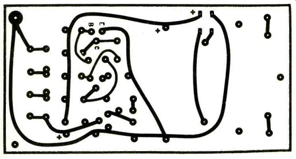
FIG. 3--BELLY-UP VIEW of the printed-circuit board foil pattern. Location of
parts can be determined from the photographs. Positioning of transistors
Q1-Q3 is given in text.
Adapted from: Radio-Electronics--Special Projects (Summer 1983, #7)
= = = =
Radio-Electronics--Special Projects (USA print magazine)
Also see: Link | --Pro Cabinets for Homebrew Projects