Modern communications receivers use a frequency readout to indicate tuning. In digitally synthesized approaches, this information is collected and displayed directly from the binarily-coded inputs. In an open loop system such as the one involving a Vfo, the frequency is displayed as a result of a frequency counter which measures the number of cycles output ted by the Vfo, and/or all other local oscillators, against a highly stable reference frequency. The result indicates with high accuracy, the tuning frequency of the receiver directly in MHz. Figure 1 shows a basic block diagram for such a frequency counter. It can be seen from this example that the programmable counter (as modified by the band and i-f correction inputs) is allowed to count the conditioned Vfo frequency, only as gated by the reference divider, resulting in a display of the actual frequency being received. Although this rather simplistic approach to a frequency counter has been adopted in many designs, the net result of such a system is the "flickering" phenomenon resulting in the ambiguous digit problem.
The timing diagram in Fig. 1, shows that the counter samples the Vfo frequency half the time and it displays it the other half. This is known as the 50/50 sampling procedure, and can be found widely in the literature and in some commercial equipment. Because the frequency of the Vfo is fully unsynchronized with the reference frequency, the counted result will al ways hesitate between two values, displaying a flickering least significant digit. The 50/50 sampling technique will only aggravate this flickering.
A well-designed frequency counter will sample for a very short time and display for a relatively long time. Shown in Fig. 2 is the timing diagram for such a counter. The Vfo frequency (data count) is counted for 100 msec and 10 msec after this count is finished, a short latch enable pulse strobes the display, thus changing the number to be viewed by the operator to a new number. This number will remain displayed for the next 140 msec while a new latch enable pulse is generated. In the meantime, the counter was reset by the count load line and a new frequency can be displayed.
Because of the very short sampling period and the relatively long retention of the displayed information, the flickering effect will be greatly minimized.
Figure 3 shows the schematic diagram for such a frequency counter as applied to the 9 MHz i-f communications receiver. Offset i-f frequencies of -± 9 MHz, as well as band corrections are automatically programmed into the counter by the band switch so that the display will read actual received frequencies. Blanking of the first digit and the decimal point are also designed in.
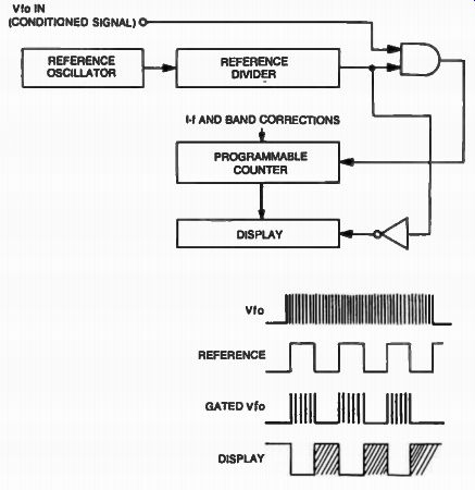
Fig. 1. Block diagram for a basic frequency counter.

Fig. 2. Timing diagram for the digital frequency counter.
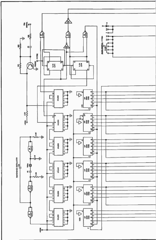
Fig. 3
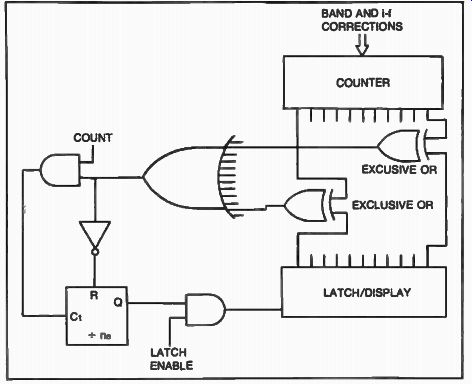
Fig. 4. An ambiguous digit detector can greatly improve the problem
of flickering in a counter.
This is accomplished through a diode matrix which is also set up to correct for the proper sideband corresponding with the particular band used. A reverse mode switch is also included if abnormal sideband reception is required by the operator. This entire interlock system should also control the bfo frequencies. This counter performs extremely smooth with no visible flicker. Further improvement in minimizing the flicker phenomenon in a frequency counter could be obtained if the command to load the latch would be only given by the system when the value in the counter is really a new value.
If the operator didn't change the frequency there is obviously no reason to refresh the display, allowing for flicker-free operation. This is accomplished by comparing the new count value with the latch/display content through the use of exclusive-OR gates as shown in Fig. 4.
In this approach any discrepancy between the displayed information and a newly counted number is detected by the Exclusive OR comparators, making the error counter increment by one. Although the latch enable pulse will be present at the end of the count as we previously discussed, the AND gate will not allow it to go through unless the error counter further detects changes in the counter content.
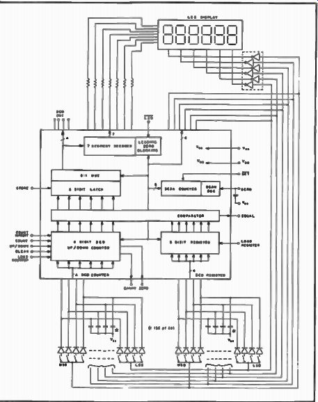
Fig. 5. Functional diagram of the Mostek MK 5039 digital counter.
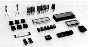
Fig. 6. Several forms of numerical displays used in a communications
receiver.
In the case of the flicker phenomenon, the last digit will jump back to the previous value if there was no change in frequency. This value is exactly that contained in the display, and when compared with it, will output all zeros to the OR gate, which in turn will reset the error counter through the inverter R. Unless there is a significant change in frequency which was confirmed several times by the error counter (the value of n e determines how sure we want to be), the display will solidly stay on the received frequency, almost totally ignoring the flickering phenomenon. I built a counter with a resolution of 100 Hz and connected it with a Vfo which had a drift of ± 40 Hz/hr at room temperature. The Vfo was locked in one position and no change in the readout frequency of the counter was observed over a period of one and a half hours.
The trend toward digital frequency counters in communications receivers leads to the introduction of a wide variety of digital components expressly made for this application. It is possible today to buy integrated circuits which will perform this function. Figure 5 shows the functional diagram of the Mostek, MK 50395 integrated circuit. This device includes a six-decade synchronous up/down-counter, storage-latches, a comparator register, and display driver circuits. A relatively inexpensive frequency counter can be built around this device. However, the multiplexed output can be of a concern in a communications receiver since its noise can directly interfere with the receiver. The static display design presented earlier allows for minimum radiation to the receiver and is superior to the multiplexed mode which generates various unwanted spurious frequencies on each edge of the square-wave signals.
To further improve on the noise performance of frequency counters, low speed digital devices should be used wherever possible. CMOS, L and LS technologies make ideal choices in implementing frequency counters.
Proper layout, ample shielding and careful bypassing will help considerably in avoiding spurious interference. When buying a receiver equipped with a digital frequency readout, listen for a multitude of noises at different frequencies with the antenna disconnected. The choice of display is also important in the design of a frequency counter for a Communications Receiver. Figure 6 shows several forms of displays, from neon discharge, through electroluminescent, LEDs, and liquid crystal display (LCD) types. The most popular display today is still the light emitting diode type.
Open collector output stages are usually used to drive these displays, and the only external component used is a current-limiting resistor, how ever this type of display can produce unwanted noise due to relatively high current transients. Fluorescent gas discharge displays are used, but driving circuits become more complex, as high voltage is required to trigger these devices. The liquid crystal display is becoming increasingly popular today.
Although this type of display requires an ac drive mechanism for the segments, the very low current requirement allows for low noise performance.
New multiplexed sinewave devices are being introduced today. They allow for transfer of information to the display at the zero crossing of the sinewaves providing nearly noise-free operation. The disadvantage of this method is that the segment drivers must be capable of driving peak currents which exceed typical light emitting diode (LED) current requirements.
In conclusion, simple and efficient frequency displays can be designed and built with the techniques presented here. Almost noise-free operation can be realized with the systems using sinewaves, and the flickering phenomenon is a problem of the past, when using ambiguous digit detectors.