THE electron tube is a marvelous device. It makes possible the performing of operations, amazing in conception, with a precision and a certainty that are astounding. It is an exceedingly sensitive and accurate instrument-the product of coordinated efforts of engineers and craftsmen. Its construction requires materials from every corner of the earth. Its use is world-wide.
The importance of the electron tube lies in its ability to control almost instantly the flight of the millions of electrons supplied by the cathode. It accomplishes this control with a minimum of energy. Because it is almost instantaneous in its action, the electron tube can operate efficiently and accurately at extremely high electrical frequencies.
Electrons
All matter exists in the solid, liquid, or gaseous state. These three forms consist entirely of minute divisions known as molecules, which, in turn, are composed of atoms. Atoms have a nucleus which is a positive charge of electricity, around which revolve tiny charges of negative electricity known as electrons. Scientists have estimated that electrons weigh only 1/30 billion, billion, billion, billionths (1/00 x 10 ^ -36) of an ounce, and that they may travel at speeds of thousands of miles per second.
Electron movement may be accelerated by the addition of energy. Heat is one form of energy which can be conveniently used to speed up the electron.
For example, if the temperature of a metal is gradually raised, the electrons in the metal gain velocity. When the metal becomes hot enough, some electrons may acquire sufficient speed to break away from the surface of the metal. This action, which is accelerated when the metal is heated in a vacuum, is utilized in most electron tubes to produce the necessary electron supply.
An electron tube consists of a cathode, which supplies electrons, and one or more additional electrodes, which control and collect these electrons, mounted in an evacuated envelope. The envelope may be made of glass, metal, ceramic, or a combination of these materials.
Cathodes
A cathode is an essential part of an electron tube because it supplies the electrons necessary for tube operation.
When energy in some form is applied to the cathode, electrons are released.
Heat is the form of energy generally used. The method of heating the cathode may be used to distinguish between the different forms of cathodes. For example, a directly heated cathode, or filament-cathode, is a wire heated by the passage of an electric current. An indirectly heated cathode, or heater cathode, consists of a filament, or heater, enclosed in a metal sleeve. The sleeve carries the electron-emitting material on its outside surface and is heated by radiation and conduction from the heater.
A filament, or directly heated cathode, such as that shown in Fig. 1 may be further classified by identifying the filament or electron-emitting material.
The materials in regular use are tungsten, thoriated tungsten, and metals which have been coated with alkaline earth oxides. Tungsten filaments are made from the pure metal. Because they must operate at high temperatures (a dazzling white) to emit sufficient electrons, a relatively large amount of filament power is required.
Thoriated-tungsten filaments are made from tungsten impregnated with thorium oxide. Due to the presence of thorium, these filaments liberate electrons at a more moderate temperature of about 1700°C (a bright yellow) and are, therefore, much more economical of filament power than are pure tungsten filaments.
Alkaline earths are usually applied as a coating on a nickel-alloy wire or ribbon. This coating, which is dried in a relatively thick layer on the filament, requires only a relatively low tempera ture of about 700-750°C (a dull red) to produce a copious supply of electrons. Coated filaments operate very efficiently and require relatively little filament power. However, each of these cathode materials has special advantages which determine the choice for a particular application.
Directly heated filament-cathodes require comparatively little heating power. They are used in tube types de signed for battery operation because it is, of course, desirable to impose as small a drain as possible on the batteries. They are also used in rectifiers such as the 1G3GTA/1B3GT and the 5Y3GT.
An indirectly heated cathode, or heater-cathode, consists of a thin metal sleeve coated with electron-emitting material such as alkaline-earth oxides. The emissive surface of the cathode is maintained at the required temperature (approximately 1050°K) by resistance heating of a tungsten or tungsten-alloy wire which is placed inside the cathode sleeve and electrically insulated from it, as shown in Fig. 2. The heater is used only for the purpose of heating the cathode sleeve and sleeve coating to an electron-emitting temperature.
Useful emission does not take place from the heater wire.
A new dark heater insulating coating developed by RCA has better heat transfer than earlier aluminum-oxide coatings, and makes it possible to operate heaters at lower temperatures for given power inputs. Because the tensile strength of the heater wire increases at the lower operating temperatures, tubes using dark heaters have increased reliability, stability, and life.
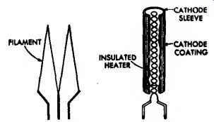
Fig. 1-Filament or directly heated cathode.

Fig. 2-Indirectly heated cathode or heater-cathode.
The heater-cathode construction is well adapted for use in electron tubes intended for operation from ac power lines and from storage batteries. The use of separate parts for emitter and heater functions, the electrical insulation of the heater from the emitter, and the shielding effect of the sleeve may all be utilized in the design of the tube to minimize the introduction of hum from the ac heater supply and to minimize electrical interference which might enter the tube circuit through the heater-supply line. From the viewpoint of circuit design, the heater-cathode construction offers advantages in connection flexibility because of the electrical separation of the heater from the cathode.
Another advantage of the heater cathode construction is that it makes practical the design of a rectifier tube having close spacing between its cathode and plate, and of an amplifier tube having close spacing between its cathode and grid. In a close-spaced rectifier tube, the voltage drop in the tube is low, and, therefore, the regulation is improved. In an amplifier tube, the close spacing increases the gain obtain able from the tube. Because of the advantages of the heater-cathode construction, almost all present-day receiving tubes designed for ac operation have heater-cathodes.
Generic Tube Types
Electrons are of no value in an electron tube unless they can be put to work. Therefore, a tube is designed with the parts necessary to utilize electrons as well as those required to produce them. These parts consist of a cathode and one or more supplementary electrodes. The electrodes are en closed in an evacuated envelope having the necessary connections brought out through air-tight seals. The air is removed from the envelope to allow free movement of the electrons and to pre vent injury to the emitting surface of the cathode.
When the cathode is heated, electrons leave the cathode surface and form an invisible cloud in the space around it. Any positive electric potential within the evacuated envelope offers a strong attraction to the electrons (unlike electric charges attract; like charges repel). Such a positive electric potential can be supplied by an anode (positive electrode) located within the tube in proximity to the cathode.
Diodes
The simplest form of electron tube contains two electrodes, a cathode and an anode (plate), and is often called a diode, the family name for a two-electrode tube. In a diode, the positive potential is supplied by a suitable electrical source connected between the plate terminal and a cathode terminal, as shown in Fig. 3. Under the influence of the positive plate potential, electrons flow from the cathode to the plate and return through the external plate-battery circuit to the cathode, thus completing the circuit. This flow of electrons is known as the plate current.
If a negative potential is applied to the plate, the free electrons in the space surrounding the cathode will be forced back to the cathode and no plate current will flow. If an alternating voltage is applied to the plate, the plate is alternately made positive and negative Because plate current flows only during the time when the plate is positive, current flows through the tube in only one direction and is said to be rectified.
Fig. 4 shows the rectified output current produced by an alternating input voltage.
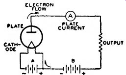
Fig. 3-Basic diode
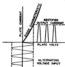
Fig. 4-Current characteristics of rectifier circuit.
Diode rectifiers are used in ac receivers to convert the ac supply voltage to dc voltage for the electrodes of the other tubes in the receiver. Rectifier tubes having only one plate and one cathode, such as the 35W4, are called half-wave rectifiers, because current can flow only during one-half of the alternating-current cycle. When two plates and one or more cathodes are used in the same tube, current may be obtained on both halves of the ac cycle.
The 6X4, 5Y3GT, and 5U4GB are examples of this type and are called full-wave rectifiers.
Not all of the electrons emitted by the cathode reach the plate. Some re turn to the cathode, while others re main in the space between the cathode and plate for a brief period to produce an effect known as space charge. This charge has a repelling action on other electrons which leave the cathode surface and impedes their passage to the plate. The extent of this action and the amount of space charge depend on the cathode temperature, the distance between the cathode and the plate, and the plate potential. The higher the plate potential, the less is the tendency for electrons to remain in the space-charge region and repel other electrons. This effect may be noted by applying increasingly higher plate voltages to a tube operating at a fixed heater or filament voltage. Under these conditions, the maximum number of available electrons is fixed, but increasingly higher plate voltages will succeed in attracting a greater proportion of the free electrons.
Beyond a certain plate voltage, however, additional plate voltage has little effect in increasing the plate current because all of the electrons emitted by the cathode are already being drawn to the plate. This maximum current, illustrated in Fig. 5, is called saturation current. Because it is an indication of the total number of electrons emitted, it is also known as emission current or simply emission.
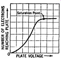
Fig. 5-Current characteristic of diode tube.
Although tubes are sometimes tested by measurement of their emission current, it is generally not advisable to measure the full value of emission because this value would be sufficiently large to cause change in the tube characteristics or even to damage the tube.
Consequently, while the test value of emission current is somewhat larger than the maximum current which will be required from the cathode in the use of the tube, it is ordinarily less than the full emission current The emission test, therefore, is used to indicate whether the cathode can supply a sufficient number of electrons for satisfactory operation of the tube.
If space charge were not present to repel electrons coming from the cathode, the same plate current could be produced at a lower plate voltage. One way to make the effect of space charge small is to make the distance between plate and cathode small. This method is used in rectifier types having heater cathodes, such as the 5V4GA and the 6AX5GT. In these types, the radial distance between cathode and plate is only about two hundredths of an inch.
Another method of reducing space charge effect is utilized in mercury vapor rectifier tubes. When such tubes are operated, a small amount of mercury contained in the tube is partially vaporized, filling the space inside the bulb with mercury atoms. These atoms are bombarded by electrons on their way to the plate. If the electrons are moving at a sufficiently high speed, the collisions tear off electrons from the mercury atoms. The mercury atom is then said to be "ionized," i.e., it has lost one or more electrons and, therefore, has a positive charge. Ionization is evidenced by a bluish-green glow between the cathode and plate. When ionization occurs, the space charge is neutralized by the positive mercury atoms so that increased numbers of electrons are made available. Mercury-vapor tubes are used primarily for power rectifiers.
Ionic-heated-cathode rectifiers depend on gas ionization for their operation. These tubes are of the full-wave design and contain two anodes and a coated cathode sealed in a bulb containing a reduced pressure of inert gas.
The cathode becomes hot during tube operation, but the heating effect is caused by bombardment of the cathode by ions within the tube rather than by heater or filament current from an external source.
The internal structure of an ionic heated-cathode tube is designed so that when sufficient voltage is applied to the tube, ionization of the gas occurs be- tween the anode which is instantaneously positive and the cathode.
Under normal operating voltages, ionization does not take place between the anode that is negative and the cathode, so that the requirements for rectification are satisfied. The initial small flow of current through the tube is sufficient to raise the cathode temperature quickly to incandescence, whereupon the cathode emits electrons. The voltage drop in such tubes is slightly higher than that of the usual hot-cathode gas rectifiers because energy is taken from the ionization discharge to keep the cathode at operating temperature. Proper operation of these rectifiers requires a minimum flow of load current at all times to maintain the cathode at the temperature required to supply sufficient emission.
Triodes
When a third electrode, called the control grid, is placed between the cathode and plate, the tube is known as a triode, the family name for a three electrode tube. The grid usually consists of relatively fine wire wound on two support rods (side-rods) and extending the length of the cathode. The spacing between turns of wire is large compared with the size of the wire so that the passage of electrons from cathode to plate is practically unobstructed by the grid. In some types, a frame grid is used.
The frame consists of two side-rods supported by four metal straps. Extremely fine lateral wire (diameter of 0.5 mil or less) is wound under tension around the frame. This type of grid permits the use of closer spacings between grid wires and between tube electrodes, and thus improves tube performance.
The purpose of the grid is to control the flow of plate current. When a tube is used as an amplifier, a negative dc voltage is usually applied to the grid. Under this condition the grid does not draw appreciable current.
The number of electrons attracted to the plate depends on the combined effect of the grid and plate polarities, as shown in Fig. 6. When the plate is positive, as is normal, and the dc grid voltage is made more and more negative, the plate is less able to attract electrons to it and plate current decreases. When the grid is made less and less negative (more and more positive), the plate more readily attracts electrons to it and plate current increases. Hence, when the voltage on the grid is varied in accordance with a signal, the plate current varies with the signal. Because a small voltage applied to the grid can control a comparatively large amount of plate current, the signal is amplified by the tube. Typical three-electrode tube types are the 6C4 and 6AF4A.
ELECTRON FLOW
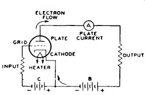
Fig. 6-Basic triode circuit.
The grid, plate, and cathode of a triode form an electrostatic system, each electrode acting as one plate of a small capacitor. The capacitances are those existing between grid and plate, plate and cathode, and grid and cathode.
These capacitances are known as inter electrode capacitances. Generally, the capacitance between grid and plate is of the most importance. In high-gain radio-frequency amplifier circuits, this capacitance may act to produce undesired coupling between the input circuit, the circuit between grid and cathode, and the output circuit, the circuit between plate and cathode. This coupling is undesirable in an amplifier because it may cause instability and unsatisfactory performance.
Tetrodes
The capacitance between control grid and plate can be made small by mounting an additional electrode, called the screen grid (grid No. 2), in the tube.
With the addition of the grid No. 2, the tube has four electrodes and is, accordingly, called a tetrode. The screen grid or grid No. 2 is mounted between the grid No. 1 (control grid) and the plate, as shown in Fig. 7, and acts as an electrostatic shield between them, thus reducing the grid-to-plate capacitance. The effectiveness of this shielding action is increased by a bypass capacitor connected between screen grid and cathode. By means of the screen grid and this bypass capacitor, the grid plate capacitance of a tetrode is made very small. In practice, the grid-plate capacitance is reduced from several picofarads (pF) for a triode to 0.01 pF or less for a screen-grid tube.
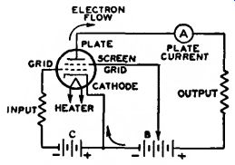
Fig. 7-Basic tetrode circuit.
The screen grid has another desirable effect in that it makes plate current practically independent of plate voltage over a certain range. The screen grid is operated at a positive voltage and, therefore, attracts electrons from the cathode. However, because of the comparatively large space between wires of the screen grid, most of the electrons drawn to the screen grid pass through it to the plate. Hence, the screen grid supplies an electrostatic force pulling electrons from the cathode to the plate.
At the same time, the screen grid shields the electrons between cathode and screen grid from the plate so that the plate exerts very little electrostatic force on electrons near the cathode.
So long as the plate voltage is higher than the screen-grid voltage, plate current in a screen-grid tube depends to a great degree on the screen grid voltage and very little on the plate voltage. The fact that plate current in a screen-grid tube is largely independent of plate voltage makes it possible to obtain much higher amplification with a tetrode than with a triode. The low grid-plate capacitance makes it possible to obtain this high amplification without plate-to-grid feedback and resultant instability. In receiving-tube applications, the tetrode has been re placed to a considerable degree by the pentode.
Pentodes
In all electron tubes, electrons striking the plate may, if moving at sufficient speed, dislodge other electrons.
In two- and three-electrode types, these dislodged electrons usually do not cause trouble because no positive electrode other than the plate itself is present to attract them. These electrons, therefore, are drawn back to the plate. Emission caused by bombardment of an electrode by electrons from the cathode is called secondary emission because the effect is secondary to the original cathode emission.
In the case of screen-grid tubes, the proximity of the positive screen grid to the plate offers a strong attraction to these secondary electrons, and particularly so if the plate voltage swings lower than the screen-grid voltage. This effect reduces the plate current and limits the useful plate-voltage swing for tetrodes.
The effects of secondary emission are minimized when a fifth electrode is placed within the tube between the screen grid and plate. This fifth electrode is known as the suppressor grid (grid No. 3) and is usually connected to the cathode, as shown in Fig. 8. Because of its negative potential with respect to the plate, the suppressor grid retards the flight of secondary electrons and diverts them back to the plate.
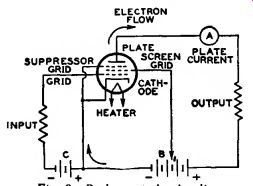
Fig. 8-Basic pentode circuit.
The family name for a five-electrode tube is "pentode." In power-output pentodes, the suppressor grid makes possible higher power output with lower grid-driving voltage; in radio-frequency amplifier pentodes, the suppressor grid makes possible high voltage amplification at moderate values of plate voltage. These desirable features result from the fact that the plate-voltage swing can be made very large. In fact, the plate voltage may be as low as, or lower than, the screen-grid voltage without serious loss in signal-gain capability. Representative pentodes used for power amplification are the 6CL6 and 6K6GT; representative pentodes used for voltage amplification are the 6AU6A, 6BA6, and 5879.
Beam Power Tubes
A beam power tube is a tetrode or pentode in which directed electron beams are used to increase substantially the power-handling capability of the tube. Such a tube contains a cathode, a control grid (grid No. 1), a screen grid (grid No. 2), a plate, and, optionally, a suppressor grid (grid No. 3).
When a beam power tube is designed without an actual suppressor grid, the electrodes are so spaced that secondary emission from the plate is suppressed by space-charge effects between screen grid and plate. The space charge is produced by the slowing up of electrons traveling from a high-potential screen grid to a lower-potential plate. In this low-velocity region, the space charge produced is sufficient to repel secondary electrons emitted from the plate and to cause them to return to the plate.
Beam power tubes of this design employ beam-confining electrodes at cathode potential to assist in producing the desired beam effects and to prevent stray electrons from the plate from re turning to the screen grid outside of the beam. A feature of a beam power tube is its low screen-grid current. The screen grid and the control grid are spiral wires wound so that each turn of the screen grid is shaded from the cathode by a grid turn. This alignment of the screen grid and control grid causes the electrons to travel in sheets between the turns of the screen grid so that very few of them strike the screen grid.
Because of the effective suppressor action provided by space charge and be cause of the low current drawn by the screen grid, the beam power tube has the advantages of high power output, high power sensitivity, and high efficiency.
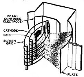
Fig. 9-Structure of beam power tube showing beam-confining action.
Fig. 9 shows the structure of a beam power tube employing space charge suppression and illustrates how the electrons are confined to beams.
The beam condition illustrated is that for a plate potential less than the screen-grid potential. The high-density space-charge region is indicated by the heavily dashed lines in the beam. Note that the edges of the beam-confining electrodes coincide with the dashed portion of the beam. In this way the space-charge potential region is extended beyond the beam boundaries and stray secondary electrons are prevented from returning to the screen grid outside of the beam. The space charge effect may also be obtained by use of an actual suppressor grid. Examples of beam power tubes are 6AQ5A, 6L6GC, 6V6GTA, and 50C5.
Multi-Electrode and Multi-Unit Tubes
Early in the history of tube development and application, tubes were de signed for a general service; that is, a single tube type-a triode-was used as a radio-frequency amplifier, an inter mediate-frequency amplifier, an audio frequency amplifier, an oscillator, or a detector. Obviously, with this diversity of application, one tube did not meet all requirements to the best advantage.
Later and present trends of tube design are the development of "specialty" types. These types are intended either to give optimum performance in a particular application or to combine in one bulb functions which formerly required two or more tubes. The first class of tubes includes such examples of specialty types as the 6CB6A and 6BY6. Types of this class generally require more than three electrodes to obtain the desired special characteristics and may be broadly classed as multi electrode types. The 6BY6 is an especially interesting type in this class.
This tube has an unusually large number of electrodes, namely seven, exclusive of the heater. Plate current in the tube is varied at two different frequencies at the same time. The tube is designed primarily for use as a combined sync separator and sync clipper in television receivers.
The second class includes multi unit tubes such as the twin-diode triodes 6CN7 and 6AV6. as well as triode-pentodes such as the 6EA8 and 6GH8A.
This class also includes class A twin triodes such as the 6FQ7/6CG7 and 12AX7A, and types such as the 6CM7 containing dissimilar triode units used primarily as combined vertical oscillators and vertical deflection amplifiers in television receivers. Full-wave rectifiers are also multi-unit types.
A third class of tubes combines features of each of the other two classes.
Typical of this third class are the penta grid-converter types 6BE6 and 6SA7.
These tubes are similar to the multi electrode types in that they have seven electrodes, all of which affect the election stream; and they are similar to the multi-unit tubes in that they perform simultaneously the double function of oscillator and mixer in superheterodyne receivers.
Receiving Tube Structure
Receiving tubes generally utilize a glass or metal envelope and a base.
Originally, the base was made of metal or molded phenolic material. Types having a glass envelope and a molded phenolic base include the "octal" types such as the 5U4GB and the 6SN7GTB.
Types having a metal envelope and molded phenolic octal base include the 6V6 and the 6L6. Many modern types utilize integral glass bases. Present-day conventional tube designs utilizing glass envelopes and integral glass bases include the seven-pin and nine-pin miniature types, the nine-pin novar and neonoval types, and the twelve-pin duo-decar types. Examples of the seven-pin miniature types are the 6AU6A and 6AV6. Examples of the nine-pin miniature types are the 12AU7A and 6EA8.
Examples of the novar types are the 6CJ3 and 7868. The nine-pin base for the novar types has a relatively large pin-circle diameter and long pins to insure firm retention of the tube in its socket.
The nuvistor concept provided a new approach to electron tube design.
Nuvistor tubes utilize a light-weight cantilever-supported cylindrical electrode structure housed in a ceramic metal envelope. These tubes combine new materials, processes, and fabrication techniques. Examples of the nuvistor are the 6CW4 and the 6DV4.
Television Picture Tubes
The picture tube, or kinescope, is a multi-electrode tube used principally in television receivers for picture display. It consists essentially of an electron gun, a glass or metal-and-glass envelope and faceplate combination, and a fluorescent screen.
The electron gun includes a cathode for the production of free electrons, one or more control electrodes for accelerating the electrons in the beam, and, optionally, a device for "trapping" unwanted ions out of the electron beam.
Focusing of the beam is accomplished either electromagnetically by means of a focusing coil placed on the neck of the tube, or electrostatically, as shown in Fig. 10, by means of a focusing electrode (grid No. 4) within the envelope of the tube. The screen is a white-fluorescing phosphor P4 of either the silicate or the sulfide type.
Deflection of the beam is accomplished either electrostatically by means of deflecting electrodes within the envelope of the tube, or electromagnetically by means of a deflecting yoke placed on the neck of the tube. Fig. 10 shows the structure of the gun section of a picture tube and illustrates how the electron beam is formed and how the beam is deflected by means of an electromagnetic deflecting yoke. In this type of tube, ions in the beam are prevented from damaging the fluorescent screen by an aluminum film on the gun side of the screen. This film not only "traps" unwanted ions, but also improves picture contrast. In many types of non-aluminized tubes, ions are separated from the electron beam by means of a tilted-gun and ion-trap magnet arrangement.
Color television picture tubes are similar to black-and-white picture tubes, but differ in three major ways:
(1) The light-emitting screen is made up of trios of phosphor dots deposited in an inter laced pattern. Each dot of a trio is capable of emitting light in one of the three primary colors (red, green, or blue).
(2) A shadow mask mounted near the screen of the tube contains over 300,000 apertures, one for each of the phosphor dot trios. This mask provides color separation by shadowing two of the three phosphor dots of each trio.
(3) Three closely spaced electron guns, built as a unit, provide separate beams for excitation of the three different color-phosphor-dot arrays. Thus it is possible to control the brightness of each of the three colors independently of the other two. Fig. 11 shows a cut away view of a color television picture tube.
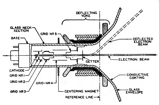
Fig. 10--Structure of television-picture-tube electron gun.
The three electron guns are mounted with their axes tilted toward the central axis of the envelope, and are spaced 120 degrees with respect to each other. The focusing electrodes of the three guns are interconnected internally, and their potential is adjusted to cause the separate beams to focus at the phosphor-dot screen. All three beams must be made to converge at the screen while they are simultaneously being deflected. Convergence is accomplished by the action of static and dynamic magnetic fields set up by the radial-converging magnet assembly mounted on the neck of the tube.
These fields are coupled into the radial converging pole pieces within the tube.
Another pair of pole pieces in the tube is activated by the lateral-converging magnet also mounted on the neck of the tube. These pole pieces permit lateral shift in position of the blue beam in opposition to the lateral shift of the green and red beams.
A purifying magnet is used with color picture tubes to provide a magnetic field, adjustable in magnitude and direction, to effect register over the en tire area of the screen. A magnetic shield is used to minimize the effects of the earth's magnetic field.
Deflection of the three beams is accomplished simultaneously by a deflecting yoke using four electromagnetic coils similar to the deflecting yoke used for black-and-white picture tubes.
A totally new concept in color television display systems utilizing an advanced design of electron gun, deflection yoke, and picture tube has been developed by RCA. Instead of dots, this tube utilizes a screen consisting of continuous vertical phosphor lines of alternating green, red, and blue emitting phosphors. The mask apertures are vertical slits with small cross ties to provide strength. This line-screen arrangement has the ad vantage of reducing beam-to-phosphor mis-register, enhancing color purity, and improving white uniformity.
The electron gun of this tube uses a horizontal in-line structure rather than the 120° spacing of the phosphor-dot tube and is designed for use with a precision static toroid line focus-type deflecting yoke. With this structure, the three beams and the deflecting field are in precise alignment.
As a result, this precision in-line tube assembly is inherently self-converging and does not require dynamic convergence correction or its associated circuitry Consequently, the deflecting yoke and neck components can be pre adjusted and permanently attached to the picture tube by the tube manufacturer.
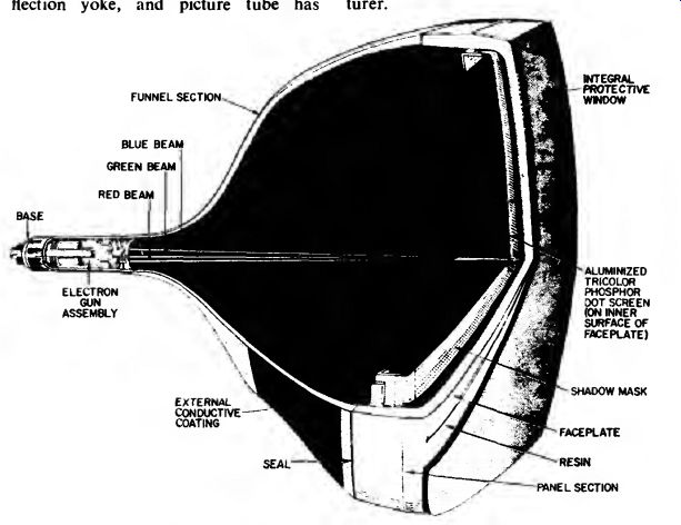
Fig. 11--Cutaway view of color television picture tube.