THE term "characteristics" is used to identify the distinguishing electrical features and values of an electron tube.
These values may be shown in curve form or they may be tabulated. When the characteristics values are given in curve form, the curves may be used for the determination of tube performance and the calculation of additional tube factors.
Tube characteristics are obtained from electrical measurements of a tube in various circuits under certain definite conditions of voltages. Characteristics may be further described by denoting the conditions of measurements. For example, Static Characteristics are the values obtained with different dc potentials applied to the tube electrodes, while Dynamic Characteristics are the values obtained with an ac voltage on a control grid under various conditions of dc potentials on the electrodes.
The dynamic characteristics, therefore, are indicative of the performance capabilities of a tube under actual working conditions.
Static characteristics may be shown by plate characteristics curves and transfer (mutual) characteristics curves.
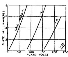
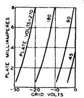
These curves present the same information, but in two different forms to increase its usefulness. The plate characteristic curve is obtained by varying plate voltage and measuring plate current for different grid-bias voltages, while the transfer-characteristic curve is obtained by varying grid-bias voltage and measuring plate current for different plate voltages. A plate-characteristic family of curves is shown in Fig. 12.
Fig. 13 gives the transfer-characteristic family of curves for the same tube.
Dynamic characteristics include amplification factor, plate resistance, control - grid-plate transconductance, and certain detector characteristics, and may be shown in curve form for variations in tube operating conditions.

Fig. 12 -Family of plate-characteristics curves.
The amplification factor, or n, is the ratio of the change in plate voltage to a change in control-electrode voltage in the opposite direction, under the condition that the plate current remains

Fig. 13--Family of transfer-characteristics curves.
unchanged and that all other electrode voltages are maintained constant. For example, if, when the plate voltage is made 1 volt more positive, the control-electrode (grid-No. 1) voltage must be made 0.1 volt more negative to hold plate current unchanged, the amplification factor is 1 divided by 0.1, or 10.
In other words, a small voltage variation in the grid circuit of a tube has the same effect on the plate current as a large plate-voltage change-the latter equal to the product of the grid voltage change and amplification factor.
The u of a tube is often useful for calculating stage gain. This use is discussed in the Electron Tube Applications section.
Plate resistance (r_p) of an electron tube is the resistance of the path be tween cathode and plate to the flow of alternating current. It is the quotient of a small change in plate voltage di vided by the corresponding change in plate current and is expressed in ohms, the unit of resistance. Thus, if a change of 0.1 milliampere (0.0001 ampere) is produced by a plate-voltage variation of 1 volt, the plate resistance is 1 divided by 0.0001, or 10000 ohms.
Control grid-to-plate transconductance, or simply transconductance (gm), is a factor which combines in one term the amplification factor and the plate resistance, and is the quotient of the first divided by the second. This term has also been known as mutual conductance. Transconductance may be more strictly defined as the quotient of a small change in plate current (amperes) di vided by the small change in the control-grid voltage producing it, under the condition that all other voltages remain unchanged. Thus, if a grid voltage change of 0.5 volt causes a plate-current change of 1 milliampere (0.001 ampere), with all other voltages constant, the transconductance is 0.001 divided by 0.5, or 0.002 mho. A "mho" is the unit of conductance and was named by spelling ohm backwards. For convenience, a millionth of a mho, or a micro-mho (u_mho), is used to express transconductance. Thus, in the example, 0.002 mho is 2000 micro-mhos.
Conversion transconductance (gc) is a characteristic associated with the mixer (first detector) function of tubes and may be defined as the quotient of the intermediate-frequency (if) current in the primary of the if transformer di vided by the applied radio-frequency (rf) voltage producing it; more precisely, it is the limiting value of this quotient as the rf voltage and if current approach zero. When the performance of a frequency converter is determined, conversion transconductance is used in the same way as control grid-to-plate transconductance is used in single-frequency amplifier computations.
The plate efficiency of a power amplifier tube is the ratio of the ac power output (P«) to the product of the aver age dc plate voltage (Eb) and dc plate current (lb) at full signal, or Plate efficiency _ Po watts ^, |qq
% Eb volts X lb amperes
The power sensitivity of a tube is the ratio of the power output to the square of the input signal voltage (Ei„).
and is expressed in mhos as follows:
Po WBttS Power sensitivity (mhos) = r=
(Ein. rms)
T X-RADIATION CHARACTERISTICS OF TELEVISION PICTURE TUBES
X-rays are produced when the atoms of a material are bombarded by electrons (or ions). The relative intensity and spectral energy distribution of the X-radiation at the source are determined by the accelerating voltage, the electron (or ion) current, and the atomic number of the bombarded materials. Because of the selective filtering effect of the glass bulb and/or of other tube components, the relative intensity external to the tube is given by the following relationship:
Relative Intensity a iV»Z
where i = current
V = accelerating voltage
Z = atomic number of the "target"
In present monochrome and color picture tubes, which use high absorption glass, "n" is the order of 20.
X-radiation also may be produced in the neck by stray electrons (or ions) that are accelerated by voltages that may be as high as the anode voltage.
This radiation is independent of that produced by the beam and, in fact, may be produced when there is no beam current; it is dependent upon voltages that are related to interelectrode potential differences or charge patterns on the glass, and upon leakage currents.