Some stereo microphone techniques work better than others. Each method has different effects. A few techniques provide sharper imaging; some create a narrow stage effect; some have exaggerated separation, and so on. In this section, I compare the characteristics of several specific stereo microphone techniques. All of these use free-field microphones; the next section covers stereo techniques using boundary microphones and dummy heads.
Localization Accuracy
One characteristic that varies among different types of arrays is localization accuracy. Localization is accurate if instruments at the sides of the ensemble are reproduced from the left or right speaker; instruments halfway off center are reproduced halfway between the center and one speaker, and so on. In other words, there is little or no distortion of the geometry of the musical ensemble.
For example, suppose your stereo speakers are spaced the same distance apart as you're sitting from them, so that each speaker is +/-30° off center. (This is the recommended arrangement for good stereo.) If the orchestral width "seen" by the microphone pair is 90°, we want sources that are 45° to one side of center to be reproduced out of only one speaker.
Sources 22.5° off-center should be reproduced halfway between the center of the speaker pair and one speaker (15° off-center).
FIG. 1 illustrates this. In FIG. 1(a), the letters A through E represent live sound-source positions relative to the microphone pair. In FIG. 1(b), the corresponding images of these sources are accurately localized between the speaker pair.
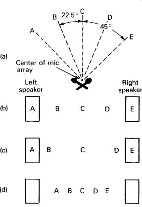
FIG. 1 Stereo localization effects for a 90° ( +/-45°) orchestral width:
(a) letters A through E represent live sound-source positions (top view); (b)
accurately localized images between speakers (listener's perception); (c) exaggerated
separation effect; and (d) narrow stage effect.
Spacing or angling the microphones more than is necessary to achieve a full stereo spread produces an "exaggerated separation" effect: Instruments near the center are reproduced to the extreme left or right, rather than slightly off-center. Instruments exactly in the center are still reproduced between the speakers (see FIG. 1(c)). Conversely, too little angling or spacing gives a poor stereo spread or a "narrow stage" effect (see FIG. 1(d)). Play CD track 20 to hear exaggerated separation and play CD tracks 9-10 to hear the narrow stage effect.
A listening test was performed to determine the localization accuracy of various stereo microphone techniques, for a 90° orchestral width ( Bartlett, 1979). Recordings were made of a speech source at 0°, 22.5°, and 45° relative to the microphone pair (as in FIG. 2(a)). Tests were made in an anechoic chamber and in a reverberant gymnasium. Listeners were asked to note the reproduced sound-image locations for several techniques.
The image locations of the anechoic and reverberant recording rooms were averaged, with results shown in FIG. 2(b).
Since results may vary under different listening conditions, this information is meant to be indicative, rather than definitive. Different listeners hear stereo effects differently, so your perceptions may not agree exactly with those shown. Still, FIG. 2 lets you compare one technique to another. Play CD tracks 8-24 to hear imaging comparisons of various stereo mic techniques.
The 90° orchestral width used is arbitrary. The actual width of the orchestra varies with the size of the ensemble and the mic-to-source distance. If the orchestral width is more than 90°, the stereo spread of all these techniques is wider than shown in FIG. 2(b).
The closer to the ensemble a microphone array is placed, the greater is the orchestral width as seen by the microphone pair, and, thus, the wider is the stereo spread (up to the limit of the speaker spacing).
Examples of Coincident-Pair Techniques
In general, coincident cardioids tend to give a narrow stereo spread and lack a sense of air or spaciousness. Imaging at high frequencies is not optimum because there is no time difference between channels, which, according to Cooper, is essential. Also, when microphones are angled apart, they receive much of the sound off axis. Many microphones have off-axis coloration (a different frequency response on and off axis).
Coincident techniques are mono-compatible: the frequency response is the same in mono and stereo. That is because there are no phase or time differences between channels to cause phase cancellations if the two channels are mixed to mono.
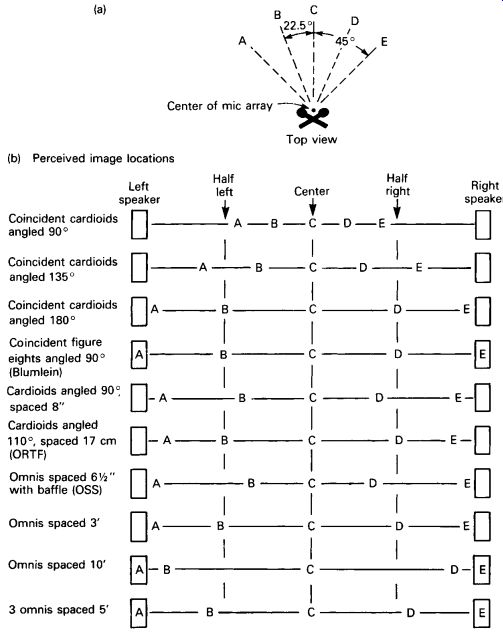
FIG. 2 Image location of some stereo mic arrays versus source position:
(a) letters A through E are live speech-source positions relative to the mic array; (b) images A through E are the perceived image locations that each stereo mic array produces.
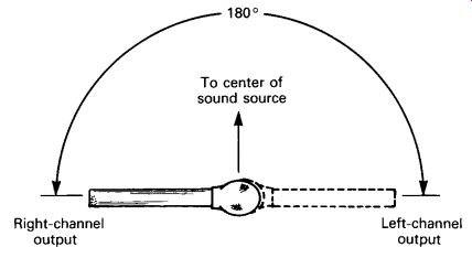
FIG. 3 Coincident cardioids angled 180° apart.
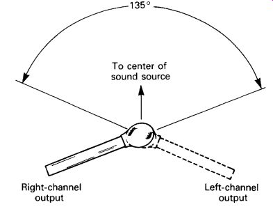
FIG. 4 Coincident cardioids angled 135° apart.
Coincident Cardioids Angled 180° Apart
According to FIG. 2(b), it seems reasonable to angle two coincident cardioid microphones 180° apart to achieve maximum stereo spread (as shown in FIG. 3). However, sounds arriving from straight ahead approach each microphone 90° off axis. The 90° off-axis frequency response of some micro phones is weak in high frequencies, giving a dull sound to instruments in the center of the orchestra. In addition, it has been the experience of another experimenter, Michael Gerzon (1976, p. 36), that 180° angling places the reproduced reverberation to the extreme left and right. Play CD track 11 to hear the imaging of coincident cardioids angled 180° apart.
Coincident Cardioids Angled 120°-135° Apart
A 120°-135° angle between microphones might be a better compromise.
Gerzon has reported that the 120° angle gives a uniform spread of reverberation between speakers, while the 135° angle (FIG. 4) provides a slightly wider stereo spread. These angles are useful when you don't want the reproduced ensemble to spread all the way between speakers. For a wider stereo spread, you can use a near-coincident or spaced pair. However, the 135° angle just described can provide a full stereo spread if the orchestral width or source angle is 150°. Play CD track 10 to hear the stereo imaging of coincident cardioids angled 120° apart.
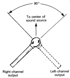
FIG. 5 Coincident cardioids angled 90° apart.
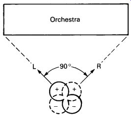
FIG. 6 The Blumlein or stereosonic technique (coincident bi-directionals
crossed at 90°).
Coincident Cardioids Angled 90° Apart
Angling cardioids at 90° (FIG. 5) reproduces most of the reverberation in the center. It gives a narrow stage width, unless the ensemble surrounds the microphone pair in a semicircle (180° source angle). Play CD track 9 to hear the stereo imaging of coincident cardioids angled 90° apart.
Blumlein Technique
This classic method uses two coincident bidirectional mics angled 90° apart (FIG. 6). As shown in FIG. 2(b), it provides accurate localization.
According to Gerzon (1976) and the listening tests, it also provides sharp imaging, a fine sense of depth, and the most uniform possible spread of reverberation across the reproduced stereo stage. It has the sharpest perceived image focus of any system, other than spatially equalized systems (Huggonet and Jouhaneau, 1987, p. 11, Figure 8).
Note that each bidirectional pattern has a rear lobe in opposite polarity to the front lobe. If a sound source is more than 45° off-center (say, off to the left side), it is picked up by the front-left lobe and the back-right lobe.
These are opposite in polarity. This creates antiphase information between channels, which produces vague localization. For this reason, the micro phones should aim at the extreme-left and -right ends of the performing ensemble. This prevents sound sources from being outside the 45° limit.
However, this limitation fixes the mic-to-source distance. You can't adjust this distance to vary the sense of perspective, unless you also change the angle between microphones or the size of the musical ensemble.
Another drawback is that the microphones pick up a large amount of reverberation. If you place the microphone pair closer to the ensemble to increase the direct/reverb ratio, the stereo spread becomes excessive and instruments in the center of the ensemble are emphasized. In addition, instruments at either end of the ensemble are reproduced with opposite-polarity signals from both channels, so they are not localized.
The Blumlein technique works best in a wide room with minimal side-wall reflections, where strong signals are not presented to the sides of the stereo pair (Streicher and Dooley, 1985).
Hypercardioids Angled 110° Apart
Shown in FIG. 7, this method give accurate localization. Listening tests also reveal sharp imaging and very good spaciousness. This array has the widest in-phase region of any array that has a spaciousness of 1 (Griesinger, 1987). The tight pattern of the hypercardioid allows a more distant placement than with crossed cardioids. As for drawbacks, hyper cardioid microphones tend to have a bass roll-off; but this can be corrected with equalization (bass boost).
Another coincident technique is the mid-side (MS) technique, which will be covered in detail later in this section.
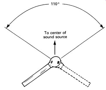
FIG. 7 Hypercardioids angled 110° apart.
Examples of Near-Coincident-Pair Techniques
If you start with a coincident pair and space the mics a few inches apart (making them near coincident), the stereo spread will increase. So will the spaciousness and depth, because of the random-phase relationships (low correlation) between channels at high frequencies.
Near-coincident methods are not mono-compatible: if both channels are combined to mono, there are dips in the frequency response caused by phase cancellations. Also, since the microphones are angled apart, the sound source might be reproduced with off-axis coloration.
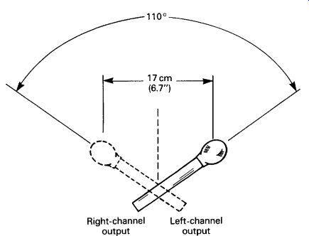
FIG. 8 The ORTF system: cardioids angled 110° and spaced 17cm (6.7 inches)
apart.
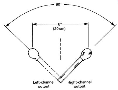
FIG. 9 The DIN system: cardioids angled 90° and spaced 20cm (8 inches)
apart.
The ORTF and DIN Systems
The listening tests summarized in FIG. 2(b) reveal that the 110° angled, 17-cm (6.7-inch) spaced cardioid array (the ORTF system) and the 90° angled, 8-inch (20-cm) spaced cardioid array (the DIN system) tend to provide accurate localization. These two methods are shown in Figures B-8 and B-9. According to a listening test conducted by Carl Ceoen (1972), the ORTF system was preferred over several other stereo miking techniques.
It provided the best overall compromise of localization accuracy, image sharpness, an even balance across the stage, and ambient warmth. Play CD track 13 to hear the stereo imaging of the ORTF technique.
The origin of the ORTF system was described by Condamines (1978).
The 17 cm (6.7 in) spacing was chosen because it provided the best image stability with head motion, assuming a speaker angle of +/-30°. The 110° angle was chosen because it provided the best image precision and placement when used with a 17 cm (6.7 in) spacing. Condamines reported that, if the mic angle is less than 110°, the sound stage usually does not spread all the way between speakers; if the angle is greater than 110°, the center image becomes weak (a hole-in-the-middle effect).
The ORTF image position varies with frequency, according to calculation (Bernfeld and Smith, 1978) and perception (Huggonet and Jouhaneau, 1987, p. 14, Figure 11).
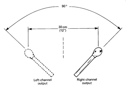
FIG. 10 The NOS system: cardioids angled 90° and spaced 30cm (11.8 inches)
apart.
The NOS System
Shown in FIG. 10, this system was proposed by the Dutch Broadcasting Foundation. It uses two cardioids angled 90° apart and spaced 30 cm (11.8 inches) horizontally. Since the spacing of the NOS system exceeds the 90° angled, 8-inch-spaced array in the listening test, we could expect it to have a slightly wider stereo spread for halfway-left and -right instruments.
Play CD track 14 to hear the stereo imaging of the NOS technique.
Examples of Spaced-Pair Techniques
In general, listeners commented that the spaced-pair methods give relatively vague, hard-to-localize images for off-center sources. These methods are useful when you want diffuse images for special effect. Spaced arrays have a pleasing sense of spaciousness. This is produced artificially by the random-phase relationships between channels, and by opposite-polarity signals at various frequencies (Lipshitz, 1986).
Spaced-pair techniques are not mono-compatible: peaks and dips in the frequency response of the direct sound occur when both channels are combined to mono. This effect may or may not be audible, because reverberation approaches the microphones from all angles, and each angle of sound incidence relates to a different pattern of phase cancellations. The reverberation randomizes the frequencies of these cancellations, so that the effect is less audible.
An advantage of the spaced-pair technique is that it allows the use of omnidirectional condenser microphones, which have a more extended low-frequency response than directional microphones. That is, the tone quality is warmer and fuller in the bass. Of course, you can equalize directional microphones to have flat bass response at a distance.
Another advantage is that the listening area for good stereo is wider than with coincident-pair techniques. The spaced-pair delay cues counteract the amplitude imbalance that occurs when the listener sits off-center.
Many instruments, such as the flute, have nulls in their sound radiation pattern that vary with the note played. Thus, one mic of a spaced pair might pick up a note at a low signal level, while the other mic would pick it up at a high signal level, so the image would wander with the note played. However, one mic will pick up notes that the other mic misses. Our ears have the same ability due to their spacing. Thus, the spaced pair offers the potential for better fidelity (no missed notes) at the expense of wandering images (Lemon, 1989).
You can use cardioids or other unidirectional patterns in a spaced array to reduce pickup of hall reverberation. These patterns, however, tend to have less bass than omnis. Spaced figure-eight mics have very little off axis coloration.
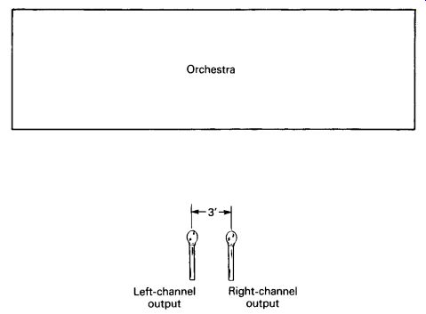
FIG. 11 Omnis spaced 3 feet apart.
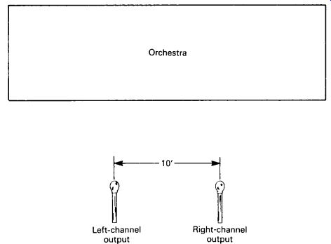
FIG. 12 Omnis spaced 10 feet apart.
Omnis Spaced 3 Feet Apart
Shown in FIG. 11, this method gives fairly accurate localization (FIG. 2(b)), but with poorly focused imaging of off-center sources. A 2-foot spacing would give more accurate localization (as in CD track 19). Since omnis must be placed relatively close to a performing ensemble for an acceptable direct/reverb ratio, this array is likely to overemphasize the center instruments. That is, the microphone pair is most sensitive to instruments in the center of the orchestra, with reduced pickup of the sides.
Telarc often uses a 2-foot spaced pair, angled 90° to each other, about 10 feet high, plus a pair of flanking omnis spaced 10-15 feet each side of center. The flanking mics are 2-3dB below the center pair. The center mics are panned partly left and right; the flanks are panned hard left and right.
Omnis Spaced 10 Feet Apart
Shown in FIG. 12, this spacing provides a more even coverage of the orchestra (a better balance). However, spacings greater than 3 feet give an exaggerated separation effect, in which instruments slightly off-center are reproduced full-left or -right (FIG. 2(b)). This dispels the myth that spaced microphones should be as far apart as the playback loudspeakers.
Instruments directly in the center of the ensemble are still reproduced exactly between the speakers. CD track 10 demonstrates the stereo imaging of two mics spaced 6 feet apart.
Three Omnis Spaced 5 Feet Apart (10 Feet End to End)
With this method (FIG. 13), a third microphone is placed between the other two, mixed in at an approximate equal level, and split to both channels. This reduces stereo separation while maintaining full coverage of the orchestra (see FIG. 2). The three-spaced-omnis technique is often used by Telarc Records. Image focus and mono-compatibility are fair to good.
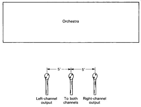
FIG. 13 Three omnis spaced 5 feet apart.
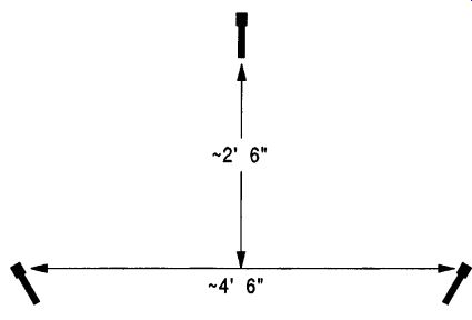
FIG. 14 Decca Tree stereo microphone technique.
Decca Tree
Developed in 1954 by the Decca Record Company, the Decca Tree is an array of three spaced omnidirectional mics (FIG. 14; Gayford, 1994; josephson.com/deccatree). Mic spacing depends on the desired amount of width and spaciousness. The center mic is placed slightly forward of the outer pair. Because the center mic's signal precedes that of the outer pair, the center mic helps to "solidify" the center image.
As for placement, the triangle of mics is mounted about 10-12 feet above the stage, just behind the conductor. The outer pair is angled outward to point at the edges of the stage, so that the edges are picked up with the best high-frequency response. Central sounds are on axis to the center micro phone. The center mic may exacerbate the comb-filtering effects that occasionally occur with spaced pairs.
Sometimes, an additional pair of flanking mics is used near the edges of the orchestra or about one-third of the way in. These flanking mics face diagonally across the orchestra and help to add width and spaciousness.
All mics are mixed at an equal level. The center mic is panned to center, both left mics are panned hard left, and both right mics are panned hard right.
Mic spacing varies with the venue and the ensemble size. The center mic or the outriggers might be omitted in some cases.
Examples of Baffled-Omni Techniques Sphere Microphone, SASS-P MKII
These mics can be called either "baffled-omni mics" or "boundary mics." They are described in Section C, Stereo Boundary-Microphone Arrays, under the headings "The Stereo Ambient Sampling System (SASS)" and "Sphere Microphones." Play CD track 17 to hear the stereo imaging of a sphere microphone.
Optimal Stereo Signal or Jecklin Disk
The Jecklin disk uses two omnidirectional microphones spaced 16.5 cm (6.5 inches) apart and separated by a disk with a diameter of 28 cm (11 7/8 inches) (Jecklin, 1981). The disk is hard and is covered with flat, absorbent material to reduce reflections (FIG. 15). The Schneider disk is the same but is covered with two foam hemispheres. The optimal stereo signal (OSS) system could be called quasi binaural, in that the human binaural hearing system also uses two omni "microphones" separated by a baffle (the head).
Below 200Hz, both microphones receive the same amplitude, and the array acts like closely spaced omnis. As frequency increases, the disk becomes more of a sound barrier, which makes the array increasingly directional. At high frequencies, the array acts like a near-coincident pair of subcardioids angled 180° apart.
Since both channels receive the same signal level at low frequencies, stereo localization at low frequencies can be due only to the capsule spacing, which causes direction-dependent delays. But, according to Griesinger (1987), delay panning does not create localizable images below 500Hz. If that is true, the OSS system localizes only above 200Hz.
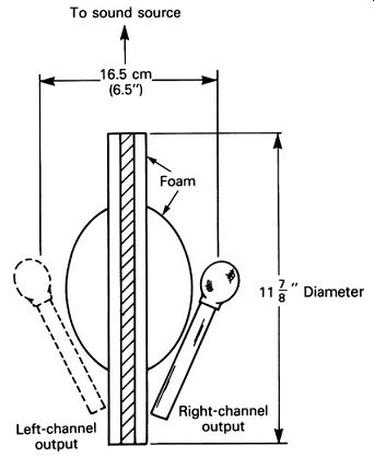
FIG. 15 The OSS system or Jecklin disk. Omnis spaced 16.5cm (6.5 inches)
apart and separated by a foam-covered disk of 28cm (11 7/8 inches) diameter.
According to the inventor (Jecklin, 1981), "the stereo image is nearly spectacular, and the sound is rich, full, and clear." It "seems to be superior to all other recording methods." The full sound is probably due to the use of omnidirectional condenser microphones, which have an extended low frequency response. Play CD track 16 to hear the stereo imaging and full bass of the Jecklin Disk method.
Listening tests (FIG. 2(b)) show that the OSS stereo spread for a 90° orchestral width is somewhat narrow. But, since the system uses omni microphones, it is usually placed close to the ensemble, where the angular width of the ensemble is wide. This results in a wider stereo spread.
Other Coincident-Pair Techniques
Let's return to coincident-pair methods and go over some specific techniques in detail.
Mid-Side
This method uses a middle (mid) microphone capsule aiming straight ahead toward the center of the performing ensemble, plus a side-aiming (side) bidirectional microphone capsule. These capsules are coincident and at right angles to each other (as shown in FIG. 16). The mid capsule is most commonly cardioid, but it can be any pattern.
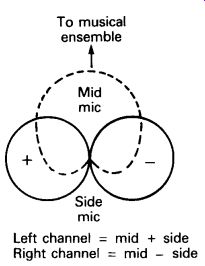
FIG. 16 MS stereo microphone technique.
The outputs of both capsules are summed (mixed) to produce the left-channel signal and are differenced (mixed in opposite polarity) to produce the right-channel signal. In effect, this creates two virtual polar patterns angled apart:
M + S = L
M - S = R
For example, suppose that the mid capsule is omnidirectional and the side capsule is bidirectional. Also suppose that the sensitivity of both capsules is set equal. When you add these two patterns together, you get a cardioid aiming 90° to the left. When you subtract these patterns (add them in opposite polarity) you get a cardioid aiming 90° to the right. Thus, an MS microphone with an omni mid capsule is equivalent to two coincident cardioids angled 180° apart. An MS microphone with a bidirectional mid capsule is equivalent to two figure-eight mics crossed at 90° (the Blumlein technique).
Some stereo microphones have switchable polar patterns. Changing the mid-capsule pattern changes the pattern and angling of the virtual polar patterns. The more directional the mid mic is, the more directional are the sum-and-difference (virtual) polar patterns (FIG. 17). Consequently, you can change the apparent distance from the sound source by changing the mid pattern.
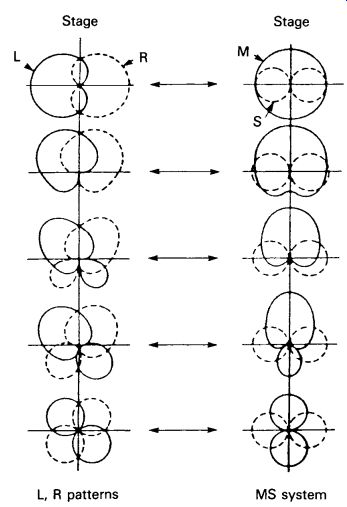
FIG. 17 Equivalent directional patterns for MS system, with mid pattern
varied. (From a letter by Les Stuck to db magazine, March 1981.)
MS Matrix Box
The M and S outputs of the microphone are connected to an MS matrix box or decoder. This decoder uses either a tapped transformer or an active circuit to sum-and-difference the M and S signals. The output of the box is a left- and a right-channel signal. Some sources of MS matrix decoders are given in Section 12 in the section "MS Matrix Decoders." A rotating knob in the box controls the ratio of the mid signal to the side signal. By varying the ratio of mid-to-side signals, you change the polar pattern and angling of the left and right virtual mic capsules. In turn, this varies the stereo spread and the ratio of direct-to-reverberant sound. As you turn up the side signal, the stereo-spread widens and the ambience increases, as shown in FIG. 18. The optimum starting M/S ratio is near 1:1.
A dual-mode matrix lets you vary the spread of an MS array, and also vary the spread of any standard left/right stereo mic array.
In Section 9 under the heading "Stereo-Spread Control," I describe how to use a computer digital audio workstation (DAW) to act as an MS matrix.
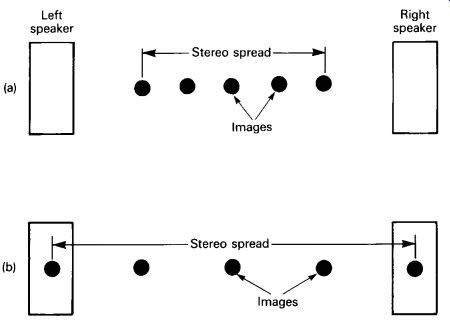
FIG. 18 Effects of varying M/S ratio on stereo spread: (a) high M/S ratio
gives a narrow spread and (b) low M/S ratio gives a wide spread.
Some MS mics have an MS matrix built in. These microphones have a left-right output and usually include a stereo-spread switch in the mic body.
MS Advantages
A major advantage of the MS system is that you can control the stereo spread from a remote location, or after the recording is done. This feature is especially useful for live concerts, where you can't change the micro phone array during the concert. Since the stereo spread is adjustable, the MS system can be made to have accurate localization.
If you record the M and S signals directly to a two-track recorder during the concert, you can play them back through a matrix decoder after the concert and adjust the stereo spread then. In postproduction, you can vary the spread from very narrow (mono) to very wide. While recording the concert, you monitor the outputs of the matrix decoder but do not record them.
The MS method has another advantage: it is fully mono-compatible.
If you sum the left and right channels to mono, you get just the output of the forward-facing mid capsule. This is shown in the following equations:
Left = (M + S)
Right = (M - S)
Left + Right = (M + S) + (M - S) = 2M
With XY- or near-coincident techniques, the center image is formed by adding the outputs of two angled directional capsules. If they are not perfectly matched in frequency and phase responses, the fusion of the center image can be degraded. But the MS system has very sharp center imaging because the center image is the output of the single mid capsule.
MS Disadvantages
The MS system has been criticized for a lack of warmth, intimacy, and spaciousness (Ceoen, 1972; Griesinger, 1987). However, Griesinger states that MS recordings can be made more spacious by giving the low frequencies a shelving boost of 4dB (starting with + 2dB at 600Hz) in the L + R or side signal, with a complementary shelving cut in the L - R or mid signal.
There are other disadvantages to the MS technique. It requires a matrix decoder, which is extra hardware to take on location. A final disadvantage is that the stereo spread and direct-to-reverb ratio are interdependent: you can't change one without changing the other.
When the signals from an MS stereo microphone are mixed to mono, the resulting signal is only from the front-facing mid capsule. If this capsule's pattern is cardioid, sound sources to the far left or right will be attenuated. Thus, the balance might be different in stereo and mono. If this is a problem, use an XY-coincident pair rather than MS.
Double MS Technique
Skip Pizzi recommends a double MS technique, which uses a close MS microphone mixed with a distant MS microphone. One MS microphone is close to the performing ensemble for clarity and sharp imaging, and the other is 50-75 feet out in the hall for ambience and depth. The distant mic could be replaced by an XY pair for lower cost (Pizzi, 1984).
For a comprehensive discussion of the MS system, see Streicher and Dooley (1985).
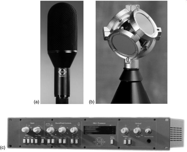
FIG. 19 SoundField Mk V Microphone: (a) external view and (b) internal
view, showing capsules.
SoundField Microphone
This British microphone (shown in FIG. 19) is an elaboration on the MS system. It uses four closely spaced cardioid mic capsules arranged in a tetrahedron and aiming outward. Their outputs are phase shifted to make the capsules seem perfectly coincident.
The capsule outputs are called the A-format signals. They are electronically matrixed by a control unit to produce:
• An omnidirectional component (the sound pressure).
• A vertical pressure-gradient component.
• A left-right pressure-gradient component.
• A fore-aft pressure-gradient component.
These B-format signals can be further processed into stereo or surround signals. With a remote-control box, the user can adjust polar patterns, azimuth (horizontal rotation), elevation (vertical tilt), dominance (apparent distance), and angle (stereo spread) (Farrar, 1979; Streicher and Dooley, 1985).
As for drawbacks, the microphone system is expensive and requires a complex matrix circuit. But it is the world's premier microphone for spatial recording. Several models are described in Section 12 under the heading "Surround Microphones."
Coincident Systems with Spatial Equalization (Shuffler Circuit)
Coincident-pair systems have been criticized for a lack of spaciousness. However, as discovered by Blumlein (1958), Vanderlyn (1954), and Griesinger (1986, 1987), the focus and spaciousness can be improved by a shuffler circuit (spatial equalization). This circuit decreases stereo separation at high frequencies or increases separation at low frequencies, in order to align the image locations at low and high frequencies. To increase low-frequency separation, the circuit applies a shelving boost to low frequencies in the left-minus-right (difference) signal, and applies a complementary cut to the left-plus-right (sum) signal.
Griesinger reports that spatially equalized coincident or near coincident arrays have very sharp imaging, and sound as spacious as a spaced array. As stated earlier, MS recordings can be made more spacious by boosting the bass + 4dB shelving ( + 2dB at 600Hz) in the L - R or side signal, and cutting the sum signal by the same amount.
Other Near-Coincident-Pair Techniques
Let's look more closely at some unusual near-coincident miking methods.
Stereo 180 System
Another near-coincident method is the Stereo 180 System developed by Olson (1979), shown in FIG. 20. It uses two hypercardioid pattern micro phones angled 135° apart, and spaced 4.6 cm (1.8 inches) horizontally. The hypercardioid patterns have opposite-polarity rear lobes, which create the illusion that the reproduced reverberation is coming from the sides of the listening room as well as between the speakers. The localization accuracy and image focus of the array are reported to be very good.
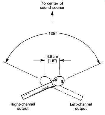
FIG. 20 Stereo 180 system: hypercardioids angled 135° and spaced 4.6cm
(1.8 inches) apart.
Faulkner Phased-Array System
Invented by Tony Faulkner (1982), this method uses two bidirectional (figure-eight) microphones aiming straight ahead with axes parallel and spaced 20 cm (7.87 inches) apart (FIG. 21). The plane of maximum sound-path difference coincides with the null in the directional polar pattern of the microphones. Since the microphones are aimed forward rather than angled apart, you can place them farther from the ensemble for a better balance. This distant placement also lets you place the micro phones at ear height, rather than raised. Faulkner says that the array is not mono-compatible in theory but has presented no problems in practice.
Sometimes Faulkner adds a pair of omnidirectional microphones 2-3 feet apart, flanking the figure eights. These omnis add ambient spaciousness.
Near-Coincident/Spaced-Pair Hybrid
John Eargle, Director of Recording at Delos International Inc., prefers to use a combination of near-coincident and spaced-pair methods (Symphonic Sound Stage CD). A quasi-ORTF pair is placed about 4 feet behind the conductor, 9-12 feet high. This pair is flanked by two omnis 12-16 feet apart, typically 6dB below the main pair. The ORTF pair provides sharp imaging and depth, while the spaced pair adds width to the strings and time cues from the hall. Since the spaced pair uses omnidirectional mics, low frequency reproduction is excellent.
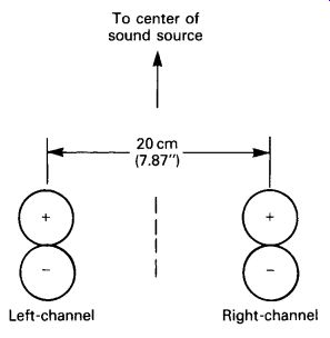
FIG. 21 Faulkner phased-array system: two figure eights spaced 20cm (7.8
inches) apart.
A second stereo pair is placed up to 30 feet behind the main pair to capture hall reverb. The woodwinds often are picked up with an overhead pair, and accent mics are added if necessary for soloists, harp, celeste, and other instruments.
Comparisons of Various Techniques
Many studies have been done comparing standard stereo miking techniques. The results of some of these are presented here. They do not all agree. Play CD tracks 8-24 to compare various techniques for yourself.
Michael Williams, "Unified Theory of Microphone Systems for Stereophonic Sound Recording" (1987)
Michael Williams calculated the recording angle and standard deviation of several fixed systems. Recording angle means the angle subtended by the sound source required for a speaker-to-speaker stereo spread. It is the angular width of the performing ensemble (as seen by the microphone array) that causes a full stereo spread.
The standard deviation represents geometric distortion of the sound stage. The bigger the standard deviation in degrees, the wider is the image separation of halfway-left and -right instruments. If standard deviation is 0°, instruments halfway left in the orchestra are reproduced halfway left between the loudspeakers (that is, at 15° off-center for speakers separated +/-30°). If standard deviation is large, this is the exaggerated separation effect mentioned earlier.
Here are his findings for various fixed mic arrays:
Coincident cardioids at 90° The recording angle is +/-90° (180° in all). In other words, the orchestra must form a semicircle (180°) around the microphone pair to be reproduced from speaker to speaker.
The standard deviation is about 6°. In other words, an instrument that is half-right in the orchestra would be reproduced 6° beyond half-right.
Coincident figure eights at 90° (Blumlein) Recording angle is +/-45° (90° in all).
Standard deviation is about 5°.
Cardioids angled 110° and spaced 17 cm (6.7 in) (ORTF) Recording angle is +/-50° (100° in all).
Standard deviation is about 5°.
Cardioids angled 90° and spaced 30 cm (11.8 in) (NOS) Recording angle is +/-40° (80° in all).
Standard deviation is about 4°.
Omnis spaced 50 cm (20 inches) Recording angle is +/-50° (100° in all).
Standard deviation is about 8°.
Williams's article has graphs showing the calculated recording angle and standard deviation for a wide range of polar patterns, anglings, and spacings, as well as other useful information.
Carl Ceoen, "Comparative Stereophonic Listening Tests" (1972)
Carl Ceoen used listening tests to compare several typical stereo techniques. He reported the following average resolution distortion (image focus or sharpness) for these methods:
XY (coincident cardioids angled 135°): 3° MS (equivalent to coincident hypercardioids angled apart): 5.5° Blumlein (coincident bidirectionals angled 90°): 4° ORTF (coincident cardioids at 110°, 17 cm (6.7 in)): 3° NOS (cardioids angled 90° and spaced 30 cm (11.8 in)): 4° Pan pot: 3°
According to Ceoen, the listening audience agreed that the ORTF system was the best overall compromise, and that the MS system lacked intimacy.
Benjamin Bernfeld and Bennett Smith, "Computer Aided Model of Stereophonic Systems" (1978)
Bernfeld and Smith computed the image location versus frequency for various stereo miking techniques. The better the coincidence of image locations at various frequencies, the sharper the imaging. Here are the condensed results:
Blumlein (coincident bidirectionals at 90°): Image focus is good except near the speakers; there, high frequencies are reproduced with a wider stereo spread than low frequencies.
Coincident cardioids angled 90° apart: Image focus is very good, but the stereo spread is very narrow.
Coincident cardioids angled 120° apart: Image focus is fairly good, but the stereo spread is narrow.
Coincident hypercardioids angled 120° apart: Image focus is good, but not excellent because high frequencies around 3 kHz are reproduced with a wider spread than low frequencies.
Coincident hypercardioids angled 120° apart, compensated with Vanderlyn's shuffler circuit (Vanderlyn, 1954): Excellent image focus and stereo spread.
Blumlein (coincident bidirectionals at 90°), compensated with shuffler circuit:
Very good image focus and stereo spread.
ORTF (cardioids angled 110° and spaced 17 cm (6.7 in)): Good image focus;
low frequencies have narrow spread and high frequencies have wide spread.
ORTF with hypercardioids: Similar to the above, with wider stereo separation.
Two omnis spaced 9.5 feet: Poor image focus; high frequencies have much wider spread than low frequencies; exaggerated separation effect.
Three cardioids spaced 5 feet: Poor image focus as above, with exaggerated separation at high frequencies.
C. Huggonet and J. Jouhaneau, "Comparative Spatial Transfer Function of Six Different Stereophonic Systems" (1987)
Huggonet and Jouhaneau used a modulated tone burst at various frequencies, plus a violin, with listening tests to compare the spatial transfer function of six different stereophonic systems. Each system has an angular dispersion (image spread) that depends on frequency. In general, the angular dispersion of coincident systems was least. The Blumlein array gave the sharpest imaging, the dummy head, and the NOS system the worst. The dummy head gave the best depth perception, followed by ORTF. MS gave the worst depth perception.
M. Hibbing, "XY and MS Microphone Techniques in Comparison" (1989)
In comparing XY and MS coincident methods, Hibbing concluded that MS has several advantages over XY:
1. The MS system can use an omnidirectional mid element, but the XY system cannot use omnidirectional capsules. Since an omni capsule generally has better low-frequency response than a uni, the MS system can have better low-frequency response than the XY system.
2. With MS, any stereo spread can be had with any polar pattern. XY is more limited.
3. With MS, a wider source angle is usable than with XY if polar pat terns with a low bidirectional component are used.
4. With MS, the mid element aims at the center of the sound source, so most of the sound arrives close to on axis. With XY, most of the sound arrives off axis and is subject to off-axis coloration.
5. With MS, both the mid- and side-polar patterns are more uniform with frequency than the patterns in the XY configuration. Consequently, the left/right polar patterns generated by MS are more uniform with frequency than those of XY.
6. With MS, the stereo spread is easy to control by a fader. With XY, the stereo spread must be adjusted mechanically. MS allows stereo spread adjustment after the session; XY does not.
7. With MS, the mid (mono sum) signal is independent of the stereo spread, so it stays consistent and predictable. With XY, the mono sum varies with the angle between the microphones.
Wieslaw Woszczyk, "A New Method for Spatial Enhancement in Stereo and Surround Recording" (1990)
Using female speech and a soprano recorder as a sound source, Woszcyk recorded the source with several stereo arrays in the diffuse field (29-80 feet from the source). Blind listening tests were done using a stereo pair of speakers and a Dolby surround system. The latter system used front left and -right speakers, a center front speaker, a center rear speaker, and left/right surround speakers.
The results are briefly summarized below: in general, listening in Dolby surround reduces the stereo separation (stage width) because of the center speaker. Mic techniques for Dolby surround should be optimized to counteract this effect.
In these descriptions, stage width means the perceived width of the stage (about +/-65° in front of the mic pair). Spatial effect means the perceived spaciousness of the concert hall:
XY at 90°: Very narrow stage width, narrow spatial effect.
XY at 180°: Extremely wide stage width and weak center image in stereo, but fairly accurate in surround. This method gave the best spatial effect of the listening test: wide, intense, and natural.
ORTF with cardioids: Fairly accurate stage width in stereo but much narrower in surround. Narrow spatial effect.
ORTF with hypercardioids: Wide stage width, "split" spatial effect.
Blumlein: Accurate stage width up to +/-45° in stereo, slightly narrower in Dolby surround. Wide and smooth spatial effect.
14-inch-spaced omni pair: Somewhat narrow stage width in stereo, even less in surround. Smooth and natural spatial effect.
Dummy head: Wide stage width in stereo, narrower in surround. Superior spatial effect: wide and smooth.
Pressure Zone Microphone (PZM) wedge (two 18-inch +/- 29-inch hard baffles angled 45°): Overly wide stage width in stereo but accurate in surround.
Superior, natural spatial effect. Somewhat honky coloration. Spherical microphones should produce equally good imaging but without coloration.
Summary
Although these experimenters disagree in certain areas, they all agree that widely spaced microphones give poorly focused imaging and that the Blumlein technique gives sharp imaging. Blumlein and Bernfeld say that the imaging of the Blumlein array can be further sharpened with a shuffler or spatial equalizer. Ceoen's results indicate that ORTF is best, but others report less-than-optimal image focus with ORTF.
The most accurate systems for frontal stereo appear to be coincident or near-coincident arrays with spatial equalization, or dual MS arrays. The near-coincident/spaced-pair hybrid method used by Delos also works quite well.
It helps to know about all the stereo techniques in order to conquer the acoustic problems of various halls or to create specific effects. No particular technique is magic; you often can improve the results by changing the microphone angling or spacing.
I recommend the following recording, which demonstrates the imaging differences among various free-field stereo microphone techniques: The Performance Recordings Demonstration of Stereo Microphone Technique (PR-6-CD), recorded by James Boyk, Mark Fischman, Greg Jensen, and Bruce Miller; available at performancerecordings.com/albums.html.
References
The Website dpamicrophones.com has a section called " Microphone University," which includes an excellent discussion of stereo microphone techniques.
Bartlett, B. "Stereo Microphone Technique." db, Vol. 13, No. 12 (December 1979), pp. 310-346.
Bernfeld, B. and Smith, B. "Computer-Aided Model of Stereophonic Systems." Paper Presented at the Audio Engineering Society Preprint No. 1321, 59th Convention, 1978-2002, p. 14.
Blumlein, A. "British Patent Specification." Journal of the Audio Engineering Society, Vol. 6, No. 2 (April 1958), p. 91. Also in Stereophonic Techniques Anthology. New York: Audio Engineering Society, 1986.
Ceoen, C. "Comparative Stereophonic Listening Tests." Journal of the Audio Engineering Society, Vol. 20, No. 1 (January-February 1972), pp. 19-27. Also in Stereophonic Techniques Anthology. New York: Audio Engineering Society, 1986.
Condamines, R. "La Prise de Son." In Stereophonic. Paris and New York: Masson Publishers, 1978.
Farrar, K. "Sound Field Microphone." Wireless World (October 1979).
Faulkner, T. "Phased Array Recording." The Audio Amateur (January 1982).
Gayford, M. Microphone Engineering Handbook. Trowbridge, Wiltshire: Focal Press, 1994.
Gerzon, M. "Blumlein Stereo Microphone Technique." Journal of the Audio Engineering Society, Vol. 24, No. 11 (January-February 1976), p. 36.
Griesinger, D. "Spaciousness and Localization in Listening Rooms and Their Effects on Recording Technique." Journal of the Audio Engineering Society, Vol. 34, No. 4 (April 1986), pp. 255-268.
Griesinger, D. "New Perspectives on Coincident and Semi-coincident Micro phone Arrays." Preprint No. 2464 (H4), Paper Presented at the Audio Engineering Society 82nd Convention, March 10-13, 1987, London.
Hibbing, M. "XY and MS Microphone Techniques in Comparison." Journal of the Audio Engineering Society, Vol. 37, No. 10 (October 1989), pp. 823-831.
Huggonet, C. and Jouhaneau, J. "Comparative Spatial Transfer Function of Six Different Stereophonic Systems." Preprint No. 2465 (H5), Paper Presented at the Audio Engineering Society 82nd Convention, March 10-13, 1987, London.
Jecklin, J. "A Different Way to Record Classical Music." Journal of the Audio Engineering Society, Vol. 29, No. 5 (May 1981), pp. 329-332. Also in Stereophonic Techniques Anthology. New York: Audio Engineering Society, 1986.
Lemon, J. "Spacing for Fidelity," letter to the editor. Recording Engineer/Producer (September 1989), p. 76.
Lipshitz, S. "Stereo Microphone Techniques: Are the Purists Wrong?" Journal of the Audio Engineering Society, Vol. 34, No. 9 (September 1986), pp. 716-744.
Olson, L. "The Stereo-180 Microphone System." Journal of the Audio Engineering Society, Vol. 27, No. 3 (March 1979), pp. 158-163. Also in Stereophonic Techniques Anthology. New York: Audio Engineering Society, 1986.
Pizzi, S. "Stereo Microphone Techniques for Broadcast." Preprint No. 2146 (D-3), Paper Presented at the Audio Engineering Society 76th Convention, October 8-11, 1984, New York.
Streicher, R. and Dooley, W. "Basic Stereo Microphone Perspectives-A Review." Journal of the Audio Engineering Society, Vol. 33, No. 7-8 (July-August 1985), pp. 548-556. Also in Stereophonic Techniques Anthology. New York: Audio Engineering Society, 1986.
The Symphonic Sound Stage, Vol. 2. Delos Compact Disc D/CD 3504.
Vanderlyn, P. British Patent Specification 23989 (1954).
Williams, M. "Unified Theory of Microphone Systems for Stereophonic Sound Recording." Preprint No. 2466 (H-6), Paper Presented at the Audio Engineering Society 82nd Convention, March 10-13, 1987, London.
Woszcyk, W. "A New Method for Spatial Enhancement in Stereo and Surround Recording." Preprint No. 2946, Paper Presented at the Audio Engineering Society 89th Convention, September 21-25, 1990, Los Angeles.