Boundary microphones (discussed in Section 7) can make excellent stereo recordings. This section explains the characteristics of several boundary mic arrays.
First, here are some ways to create basic stereo arrays using boundary microphones ( Bartlett, 1999):
• To make a spaced-pair boundary array, space two boundary micro phones a few feet apart. Place them on the floor, on a wall, or on stand-mounted panels.
• To make a coincident array, mount two boundary mics back-to-back on a 2-foot +/- 2-foot clear plastic panel, with the edge of the panel aiming at the sound source.
• To make a near-coincident array, mount each boundary microphone on a separate panel, and angle the panels apart to form a "V." Or use two directional boundary mics on the floor, angled and spaced.
Boundary microphones can be placed directly on the floor or can be raised above the floor. We explain several stereo techniques using both methods.
Techniques Using Floor-Mounted Mics
You can place two boundary microphones on the floor to record in stereo.
Floor mounting provides several advantages:
• Phase cancellations due to sound reflections off the floor are eliminated.
• Floor mounting provides the best low-frequency response for boundary microphones.
• The mics are very easy to place.
• The mics are nearly invisible. At live concerts, hiding the microphones is often the main consideration.
When a floor-placed boundary array is used to record an orchestra, the front-row musicians are usually reproduced too loudly, due to their relative proximity to the microphones. Musical groups with little front-to-back depth-such as small chamber groups, jazz groups, or soloists-may be the best application for this system.
Let's consider specific techniques for floor-mounted microphones.
Floor-Mounted Boundary Microphones Spaced 4 Feet Apart
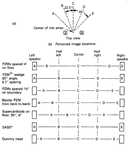
Listening tests showed that a spacing of 3-4 feet between microphones is sufficient for a full stereo spread, when the sides of the musical ensemble are 45° off-center, from the viewpoint of the center of the microphone array (see FIG. 1). Listen to CD track 22 to hear the stereo imaging of two floor-mounted PZMs (Pressure Zone Microphones) placed 3 feet apart.
With a floor-placed array, the stereo spread decreases as the sound source height increases. For example, if you record a group of people who are standing, the spread will be narrower than if the people are sitting. That's because the higher the source is, the less the time difference is between microphones.
Spaced boundary mics have the same drawbacks as spaced free-field mics: poorly focused images, potential lack of mono-compatibility, and large phase differences between channels. Listen to CD track 22 to hear the stereo imaging of two floor-mounted PZMs placed 3 feet apart.
Two advantages, however, are a warm sense of ambience and a good stereo effect even for off-center listeners. And, with a spaced pair, you can use omnidirectional boundary microphones without Plexiglas boundaries.
So the low-frequency response is excellent and the mics are inconspicuous.

FIG. 1 Stereo localization of some stereo boundary-microphone arrays:
(a) letters A through E are live speech-source positions relative to mic array;
(b) A through E are the perceived image locations produced by the mic arrays.
Floor-Mounted Directional Boundary Microphones
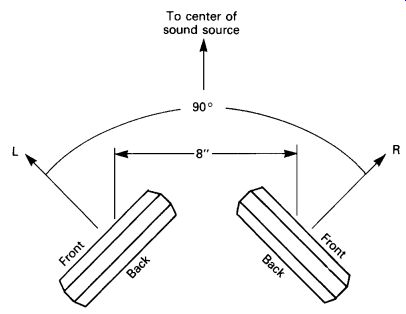
Two of these can be set up as a near-coincident pair or a spaced pair. For near-coincident use, place the mics on the floor side by side and angle them apart (FIG. 2). Adjust their angling and spacing for the desired stereo spread. This is an effective arrangement for recording stage plays or musicals. Other mics are needed for the pit orchestra.
As shown in FIG. 1, a floor-mounted array of supercardioid boundary mics, angled 90° and spaced 8 inches, provides a narrow stage width. More spacing or angling is needed for accurate localization. The image focus is sharper with this arrangement than with spaced boundary microphones. CD track 23 demonstrates the stereo imaging of a pair of cardioid boundary mics angled 90° and spaced 12 inches.

FIG. 2 Floor-mounted directional boundary microphones set in a near coincident
array.
Optimal Stereo Signal Boundary-Microphone Floor Array
In this configuration by Josephson Engineering (1988), two boundary micro phones are on opposite sides of a hard, absorbent baffle or Jecklin disk cut in half. This array has the characteristics of the Optimal Stereo Signal (OSS) system described in the previous section plus the advantages of boundary miking.
"The Musician's Ear" Stereo Boundary Microphone
This unit has two condenser mics flush-mounted in opposite sides of a wooden baffle that sits on the floor (performancerecordings.com/ ear.html).
Floor-Mounted Boundary Microphones Configured for Mid-Side
The mid-side (MS) technique can be applied to boundary microphones.
The following method was invented by Jerry Bruck (1985) of Posthorn Recordings. The mid unit is an omnidirectional boundary microphone; the side unit is a small-diameter bidirectional condenser microphone mounted a few millimeters (a few thousandths of an inch) above the omni unit.
The bidirectional microphone is close enough to the boundary to prevent phase cancellations between direct and reflected sounds over most of the audible spectrum.
Since the mid microphone is a boundary type, it has the same high frequency response anywhere around it (no off-axis coloration). This con tributes to very sharp stereo imaging. And since the mid capsule is an omni condenser unit, it has excellent low-frequency response. The system is low profile and unobtrusive.
Like other floor-mounted methods, this system is limited to recording small ensembles or soloists. It also could be used on a piano lid. No microphones are made this way; you must set a bidirectional microphone over a boundary microphone to form the array.
Techniques Using Raised Boundary Mics
If you mount two omni mic capsules on boundaries, such as panels or a sphere, the mics become directional. You can raise the panel or sphere several feet off the floor to record large ensembles in stereo. We will describe two mics of this type.
The Stereo Ambient Sampling System
This is a stereo condenser microphone using boundary-microphone technology (Bartlett, 1989; Billingsley, 1987, 1989a, 1989b, 1989c). It is designed to give sharp stereo imaging for loudspeaker or headphone reproduction. The device is a mono-compatible, near-coincident array. According to sound-mixer Gary Pillon, a stereo ambient sampling system (SASS) mounted on a Steadicam platform gives an excellent match between audio and video perspectives.
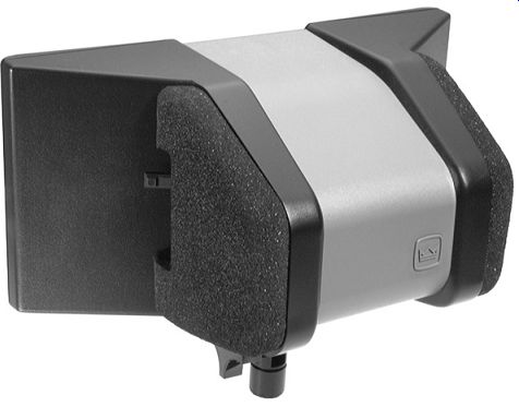
The SASS uses two PZMs mounted on boundaries to make each micro phone directional (as shown in FIG. 3).
For each channel, an omni mic capsule is mounted very near a 5-inch square boundary. The two boundaries are angled left and right of center.
The sound diffraction of each boundary, along with a foam barrier between the capsules, creates a directional polar pattern at high frequencies. The patterns aim left and right of center, much like a near-coincident array. The capsules are "ear-spaced" 17 cm (6.7 inches) apart.

FIG. 3 Crown SASS-P MKII PZM stereo microphone (Crown Inter
national, Inc.).
The polar patterns of the boundaries and the spacing between capsules have been chosen to provide natural perceived stereo imaging. Like an artificial head (described in Section D), the SASS localizes images by time and spectral differences between channels.
The foam barrier or baffle between the capsules limits acoustic crosstalk between the two sides at higher frequencies. Although the microphone capsules are spaced apart, little phase cancellation occurs when both channels are combined to mono because of the shadowing effect of the baffle. That is, despite phase differences between channels, the extreme amplitude differences (caused by the baffle) reduce phase cancellations in mono.
Application notes for the SASS are given in Bartlett (1989) and Billingsley (1987, 1989a, 1989b, 1989c, 1990).
Sphere Microphone
A sphere microphone uses a hard globe 8 inches in diameter, with a pair of pressure-response omni mic capsules flush-mounted in either side, 180° apart. Two examples are the Neumann KFM 100 and the Schoeps KFM 6.
Like the SASS, a spherical stereo mic uses time and spectral differences between channels to create stereo images. A circuit corrects the frequency response and phase response of the capsules in the sphere.
Claimed benefits are accurate and sharp imaging, excellent reproduction of depth, extended low-frequency response, and low pickup of wind and vibration. The sphere shape is used because it provides the least diffraction (disturbance of the sound field). As a result, the frequency response is flat not only for sounds in front of the sphere but also for reverberant, diffuse sound. Play CD track 17 to hear the stereo imaging of a sphere microphone. It is two mini omni mics taped to either side of a head-size sphere.
The mic is largely mono-compatible because, in the bass frequencies, phase shift is small; and, in the high frequencies, the acoustic shadow of the sphere produces strong interchannel differences making phase cancellations less probable.
A sphere mic is not the same as a dummy head. Sphere-mic recordings are for speaker listening; dummy-head recordings are for headphone listening.
References
Bartlett, B. "An Improved Stereo Microphone Array Using Boundary Technology: Theoretical Aspects." Preprint No. 2788 (A-1), Paper Presented at the Audio Engineering Society 86th Convention, March 7-10, 1989, Hamburg.
Bartlett, B. Crown Boundary Microphone Application Guide. Elkhart, IN: Crown International, 1999. crownaudio.com Billingsley, M. US Patent 4,658,931 ( April 21, 1987).
Billingsley, M. "Practical Field Recording Applications for an Improved Stereo Microphone Array Using Boundary Technology." Preprint No. 2788 (A-1), Paper Presented at the Audio Engineering Society 86th Convention, March 7-10, 1989a, Hamburg.
Billingsley, M. "An Improved Stereo Microphone Array for Pop Music Recording." Preprint No. 2791 (A-2), Paper Presented at the Audio Engineering Society 86th Convention, March 7-10, 1989b, Hamburg.
Billingsley, M. "A Stereo Microphone for Contemporary Recording." Recording Engineer/Producer (November 1989c).
Billingsley, M. "Theory and Application of a New Near-Coincident Stereo Microphone Array for Soundtrack, Special Effects and Ambience." Paper
Presented at the Audio Engineering Society 89th Convention, September 21-25, 1990, Los Angeles.
Bruck, J. "The Boundary Layer Mid/Side (M/S) Microphone: A New Tool." Preprint No. 2313 (C-11), Paper Presented at the Audio Engineering Society 79th Convention, October 12-16, 1985, New York.
Josephson Engineering. Catalog. San Jose, CA: Josephson Engineering, 1988.