2-1. Basic Parts of A-M Generators
The central and most important part of any signal generator is the r-f oscillator. This oscillator must be adjustable to any frequency within the desired specified frequency range, adjustable to any set frequency (as with crystal control) available, or both. In most generators of the a-m type, continuous frequency coverage is provided from somewhere near 100 khz to between 30 and 60 mhz. The oscillator is designed to operate with good stability, and its frequency is controlled over each range with a tuning dial calibrated in kilocycles or megacycles.
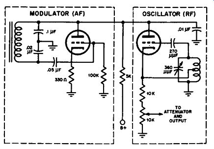
Fig. 2-1. The basic ports of any a-m signal generator ore the r-f oscillator
and the modulator. Typical circuit arrangements for these two basic ports ore
shown here.
A large percentage of the uses of a-m signal generators requires that the output signal be modulated by some kind of tone. 400 hz has been chosen as the standard single tone for modulation in testing radio receivers, with 1,000 hz as an alternate. Usually the modulation is applied to the carrier signal from the oscillator by means of a modulator tube and circuit. Simple Heising plate modulation is common. A typical circuit for an r-f oscillator and modulator in a signal generator is illustrated in Fig. 2-1. The r-f oscillator is a triode grounded-plate Hartley type. The modulator is a Colpitts a-f oscillator. The modulation is applied to the r-f oscillator by connecting the plates together as shown, and feeding B-plus to both through a common resistor of 5,000 ohms.
2-2. R-F Output Attenuators
The various applications of signal generators require a variety of signal strengths for testing, measuring, and aligning. Sometimes different signal-voltage outputs are required in rapid succession, as in radio receivers when the signal is to be injected into different stages. In some equipment, excessive signal overloads the circuits, giving false indications. If the signal is not reduced in some practical manner to just the proper value, tests are difficult or impossible. For this reason, some device for controlling the r-f voltage output is usually included. This device is called an attenuator.
Attenuators may take the form of a continuously variable control or of a step-switch, which changes the output voltage by a specified ratio (ordinarily 10 to 1) for each successive switch position or step.
Sometimes the continuously variable type is included alone, without the step type. The step type, however, is nearly always accompanied by the continuous type, since the latter provides a fine adjustment to provide variations of signal voltage between the step attenuator positions.
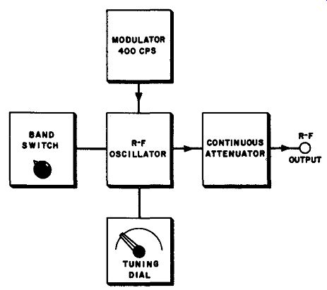
Fig. 2-2. Block diagram of the simplest service-type a-m signal generator.
2-3. Panel Arrangement For Simple A-M Generator
One of the simplest arrangements for an a-m generator is that in which a variable r-f oscillator is modulated approximately 30 percent by a modulator with a fixed tone and the modulation percentage is not variable. The block diagram of such an arrangement is shown in Fig. 2-2. The r-f output voltage is controlled by a simple continuous attenuator. The panel arrangement typical of such generators is illustrated in
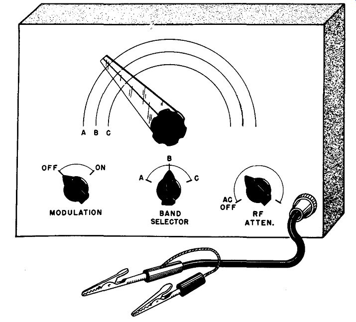
Fig. 2-3. Typical panel layout for simple service-type a-m signal generator.
Fig. 2-3. Frequently there is a switch by which modulation can be turned on or off, without any variation of the modulation percentage. The a-c switch for turning the generator on is mounted on the back of the r-f attenuator and operates at the lower end of the range of that control.
2-4. More Elaborate Arrangement
The block diagram of an a-m generator with several additional features is shown in Fig. 2-4, and a typical panel arrangement is illustrated ...
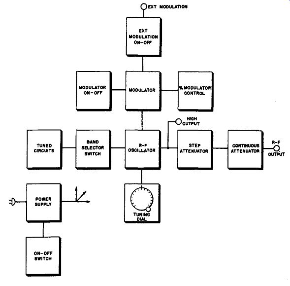
Fig. 2-4. Typical arrangement far a-m signal generator with most ordinarily
used features. This arrangement is typical a-f many service type and laboratory
type a-m generators.
... in Fig. 2-5. Here the modulation percentage is controlled by an additional knob, which is mounted on a volume control in the modulator circuit. Another feature included here is the jack for external modulation. Often the r-f signal is to be modulated by different audio frequencies for a series of tests, or the modulation frequency must be some other than that supplied in the generator unit itself.
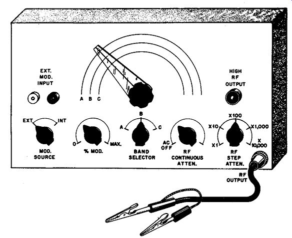
Fig. 2-5. Typical panel layout for signal generator for the type
illustrated by the block diagram of Fig. 2-4.
The external modulation provision allows the use of an external a-f oscillator, whose frequency or waveform can be varied at will, to modulate the r-f oscillator. An example of such a situation is the test of the overall frequency response of a radio receiver. The r-f signal is applied to the receiver and is modulated. The a-f modulation signal voltage at the loudspeaker is then measured for various modulation frequencies. For each modulation frequency, the external a-f oscillator is adjusted to apply the same a-f voltage at the external modulation jack of the signal generator.
When an external modulation connection is provided, there must also be a switch to select external or internal modulation. This switch turns off the internal a-f oscillator when in the external position.
Also included in the controls of the panel of Fig. 2-5 is a step attenuator. As previously explained, this device provides a change of 10 to 1 (or other ratio) in the output signal voltage for each change in position of the switch. For example, suppose there is an output voltage of 100 microvolts with a given setting of the continuous r-f attenuator and the step attenuator on the "x1" position. If the step attenuator is then changed to the "X10" position, the output voltage goes to 1,000 micro-volts. In the "X100" position, the output goes to 10,000 microvolts and so on. Attenuators are usually designed to keep the output impedance of the generator the same for all output voltage levels, or as nearly the same as possible. A standard value for output impedance is 75 ohms, or 50 ohms, which matches the characteristic impedance of the output lead.
This matching is very important at the higher frequencies (above 20 mhz).
As the output lead length becomes an appreciable fraction of a wave length, standing waves start to interfere in certain applications if impedances are not properly matched. More is said about matching in Section 7.
2-5. Output Indicators
In making sensitivity, selectivity, and other tests on radio receivers, it is important that some method of signal generator output voltage indication be available. A few service-type signal generators, and many laboratory types, include a meter by which output voltage for any setting of the attenuators can be observed. The meter may read microvolts directly, or may have a setting knob adjustment to set the meter at a certain mark on the scale, after which the attenuator controls indicate output voltage directly. A typical panel arrangement for an a-m signal generator with an output meter is shown in Fig. 2-6.
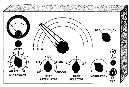
Fig. 2-6. Typical panel layout for signal generator using a meter-type output
indicator.
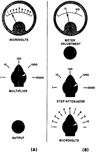
Fig. 2-7. Two methods in which a meter is used to indicate r-f output voltage
of a signal generator. At (A) the meter reads microvolts directly, and its
indication is multiplied by the multiplier dial indication. At B, the meter
is used to set the reference voltage, after which the output is read from the
dials.
The two methods used to determine the actual output voltage by means of a meter and controls are illustrated in Fig. 2-7. In the arrangement of (A), the meter reads directly in microvolts; the multiplier control selects the desired range. For example, with the meter reading of 2 and multiplier setting of 100 as shown in the figure, the output voltage is indicated as 200 microvolts. At (B) is shown another arrangement.
The meter is used to set the output reference level at an indicated point, and the output voltage is then indicated by the settings of the step attenuator and microvolts knobs. For example, with the settings shown, the output is 600 microvolts. This is obtained by multiplying the micro volts control reading (6) by the step attenuator reading (100) by the multiplier indication of the meter, which in the case shown is I. In some cases, there is only one reference mark on the meter; in these cases the multiplier is always I. The procedure in setting the arrangement at (A) for a desired output voltage is to set the multiplier for the correct range, then increase the signal voltage with the output control until the meter reading, when multiplied by the setting of the multiplier, indicates the required output level.
The procedure in setting the arrangement at (B) for a desired out, put voltage is to set the microvolts and step-attenuator dials for the desired voltage, then use the meter adjuster to set the meter pointer to X1. If a high voltage is desired, it may be more convenient to set the microvolts and attenuator controls for one-tenth the desired voltage, then set the meter for X10, if such a reference mark is provided.
A variation of the method of (B) is one which uses a tuning eye instead of a meter. In other words, when the adjuster knob is set to close the eye, it is the same as though the meter were set to XI in generators having a meter.
2-6. Audio-frequency Output
It is often desirable to have an a-f signal available from the r-f signal generator for tests of the a-f sections of receivers, a-f amplifiers, and many other applications. Since some kind of a-f oscillator is required for modulation, the same oscillator can be used to provide a-f output, and this is done in many a-m generators. The audio output is obtained either from a separate output jack, or from the r-f output jack with a different setting of one or more of the controls. Except in very special types, the a-f signal is of one frequency, the same as that used to modulate the r-f signal.
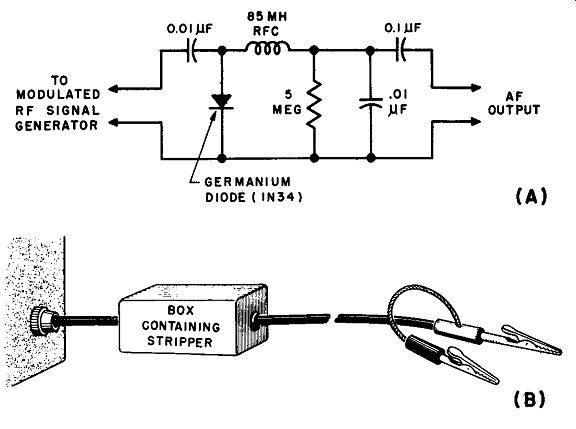
Fig. 2-8. If audio-frequency output is not directly available from the signal
generator, it may be obtained from the modulated signal by an "audio stripper".
A typical circuit and physical arrangement is shown here.
2-7. A-F Strippers
Quite a few signal generators in which modulation of the r-f signal is obtainable do not have an a-f signal available at an output terminal.
In such a case, an audio signal may be obtained by using what is known as an audio stripper, which removes the modulation signal after the modulated r-f leaves the generator unit. A typical circuit for a stripper (also sometimes called an audio extractor) is shown in Fig. 2-8. For practical use, the stripper circuit can be built into a metal box connected into an extra lead used only for a-f output, as shown in the figure.
Alternatively, a fitting may be mounted on the lead side of the box and the regular r-f lead connected at that point when a-f output is desired. The signal-generator side can then be connected by means of a short lead from the box with a fitting to go on the generator output jack.
2-8. Crystal Controlled A-M Generators
A high degree of accuracy and stability of carrier frequency are possible with crystal-controlled oscillators. These make use of quartz crystals, which keep the oscillator frequency very nearly constant at a specified frequency.
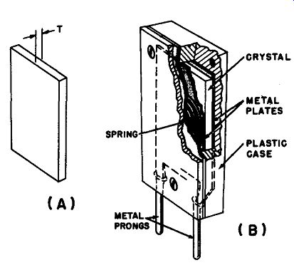
Fig. 2-9. (A) Appearance of a quartz oscillating crystal. (B) How the crystal
is mounted in a crystal holder. This holder plugs into a socket usually mounted
on the front panel of the signal generator.
A quartz crystal is a flat slab of quartz usually of square or rectangular shape, as illustrated at (A) of Fig. 2-9. Occasionally, circular slabs are used. Quartz has the property of generating a small voltage between surfaces when physical pressure is applied or released from these surfaces.
This is known as the piezo-electric effect. A properly ground crystal has a mechanical resonant frequency just as a vibrating reed or string of a musical instrument. The piezo-electric effect links a voltage across the surfaces of the crystal to the mechanical vibrations, so that the mechanical vibrations control the frequency of an oscillator into which the crystal is connected. The crystal, when oscillating, actually varies its surface pressure and flexes its mechanical structure at the radio frequency for which it is ground. The piezo-electric effect translates this mechanical action into a radio-frequency voltage across the crystal's surfaces. Since the mechanical resonant frequency depends largely upon the thickness of the crystal (t in Fig. 2-9), the electrical resonant frequency does also. The higher the resonant frequency, the thinner the crystal.
To obtain proper action from the crystal, it is mounted in a holder, as shown at (B) in Fig. 2-9. A metal plate is placed against each surface of the crystal, and these metal plates are connected respectively to two metal prongs protruding from the bottom of the holder. In many holders, a spring is added to provide gentle pressure of the metal plates against the crystal surfaces.
A crystal has the effect in an oscillator hook-up of a resonant circuit of extremely high Q, far higher than would be possible with any practical combination of coil and capacitor. A good crystal will oscillate at only one fundamental frequency, and can thus be depended upon, within certain tolerances, to be very close to specified frequency if it operates at all.
In general, crystals for fundamental frequencies up to 10 mhz are commonly available, and others up to 20 mhz can also be obtained. Special types are manufactured to operate on a "mode" of the crystal, so that operation is at some odd multiple of the fundamental frequency (usually the third or fifth). These are available for frequencies as high as 70 mhz.
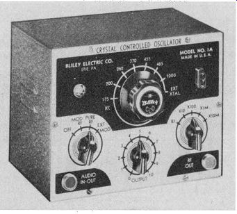
Fig. 2-10. A typical crystal-controlled o-m signal generator.
Crystals are of particular interest in signal generators because they are used for two main purposes: (1) to control the frequency of the main r-f oscillator and thus provide "spot" frequencies, each controlled by its own crystal, which are very accurate and stable, and (2) to provide check frequencies against which self-excited r-f oscillators in generators can be checked and calibrated.
A typical signal generator which is completely crystal controlled is shown in Fig. 2-10. A switch provides selection of any one of seven crystals mounted inside the unit for a crystal plugged into an external socket on the front panel. Supplied with the unit is a crystal on each of the following intermediate frequencies: 175, 262, 370, 455 and 465 khz.
For other applications, the other two crystals inside the unit are for 200 khz and 1,000 khz. These are primarily for harmonic output. That is, output from the 200 -khz crystal can be obtained at the fundamental frequency of 200 khz and also at 400, 600, 800, 1,000, 1,200, 1,400, 1,600 khz, etc., and every 200 khz well up through the short-wave range. In the same way, harmonics of the 1,000 -khz oscillator are available. Harmonic operation is discussed further in Sec. 2-9.
More frequently, crystal oscillators are used as auxiliary equipment in signal generators for checking calibration of the variable self-excited oscillators employed for the main r-f carrier output source. The variable oscillator has the advantage that it can be changed a little on either side of the desired alignment or test frequency and is useful when alignment frequencies are to be changed slightly to avoid interference. For this reason the latter type is most popular as the main oscillator; however, because there is no crystal to constrain it, its calibration is subject to variations with aging, temperature, humidity, and human error in operation. Consequently, the crystal calibrating oscillator is an important adjunct for checking variable oscillator frequency.
Because crystal frequency checking and calibrators are most closely related to markers and marker generators, they are discussed in Section 3.
2-9. Harmonic Operation of A-M Generators
Except when special design measures are taken, practically all r-f oscillators generate harmonic components of appreciable magnitude, as well as the fundamental frequency component. A harmonic component is one having a frequency equal to exactly an integral multiple of the main specified fundamental frequency of the generating oscillator.
For example, suppose we build an oscillator whose tuned circuit resonates at 1,000 khz. The oscillator oscillates at that frequency and produces a signal accordingly. However, also emanating from that same oscillator will be a radio-frequency signal at 2,000 khz, another at 3,000 khz, another at 4,000 khz, and so on, up to relatively high multiples of the basic 1,000 -khz main frequency. The 1,000 -khz frequency is known as the fundamental frequency. The individual harmonics are named after the number by which the fundamental frequency must be multiplied.
The 2,000-khz harmonic is called the "second harmonic" because the fundamental frequency of 1,000 khz must be multiplied by 2. In the same way the 3,000-khz harmonic is called the "third harmonic," the 4,000 -khz harmonic the "fourth harmonic" and so on.
In some applications, the presence of harmonics is annoying, but in signal generators it can sometimes be helpful. One oscillator frequency can be made to do for two or more. For example, our 1,000 -khz oscillator can also be used to align a receiver at 2,000 khz, 3,000 khz, and other harmonic frequencies, as well as at the fundamental of 1,000 khz.
Employing this principle, many a-m signal generators provide extended frequency range without additional coils by specifying the use of harmonics for the highest range. For example, suppose the highest fundamental frequency range were 15 to 30 mhz on a given generator.
Another range, employing the second harmonic, would provide 30 to 60 mhz with the same generator settings as for the 15 to 30 mhz range. The generator would remain exactly the same, but the receiver or other device with which the generator is used would be tuned to frequencies in the higher range, and the dial-calibration frequencies would all have to be multiplied by 2. In many of the signal generators in which harmonics are to be employed, the dial is calibrated for both fundamental and harmonic frequencies, wherever the latter are recommended. Then, instead of having to multiply each value by 2 (or other whole number multiples) the operator may refer to the additional scale calibrated in values which are a multiple of the actual fundamental frequencies. Most manufacturers of signal generators will specify what ranges of frequencies are covered by the fundamental and what ranges employ harmonics.
In the same way, harmonics of crystal-controlled oscillators are avail able. If we have. a 1,000-khz crystal oscillator, we also have available harmonic components at 2, 3, 4, 5, etc. mhz. As will be explained in Section 3, these harmonics provide convenient check points against which the calibration of the variable oscillator can be checked.
One important fact must be kept in mind wherever harmonics are involved. Any imperfection in the fundamental signal is multiplied in the harmonic components. For example, a frequency error of 1 khz in a fundamental frequency of 1,000 khz will be reflected as a frequency error of 10 khz at the tenth harmonic of 10 mhz. In other words, the frequency variations maintain the same percentage no matter what harmonic component is used. Accordingly, what may be a negligible error on the fundamental frequency may be excessive on a harmonic component being employed on a test. This is discussed further in Section 5.
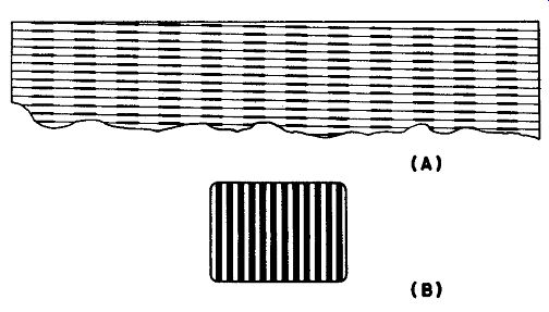
Fig. 2-11. How vertical bars are formed in a tv raster by presence of a modulation
signal of a frequency considerably higher than the horizontal-deflection frequency.
Several modulation signal cycles take place during one horizontal line period, thus producing a series of black spots along the line. When the frequency ratio is just right, the black spots on the successive lines align themselves, producing the vertical bars.
2-10. Cross-hatch Generators
A special type of a-m signal generator is used to test linearity and other factors in tv reception. This is known as the "cross-hatch" generator or linearity-pattern generator. One type, which is designed to produce a series of parallel strips, or bars, on the screen of the tv receiver, is sometimes called a "bar generator." A bar generator may be designed to produce horizontal or vertical bars only. A cross-hatch generator, on the other hand, produces vertical and horizontal bars at the same time.
For proper linearity, the parallel bars in each direction should remain equidistant and of the same thickness.
Generators of this type merely produce an r-f signal of the inter mediate frequency or the front-end frequency of the tv receiver, amplitude-modulated by a relatively high frequency (200 to 400 khz) for vertical bars, and by an audio frequency (500 to 2,000 hz) for horizontal bars.
How the vertical bars are formed is illustrated in Fig. 2-11. The modulation signal will be assumed to be about 200 khz. This signal is recovered from the carrier by the video second detector in the receiver, amplified, and applied to the grid of the picture tube. Whenever the modulation signal goes through a negative peak (once each cycle) the picture tube beam is blanked and a dark spot appears in the trace.
If the modulation signal frequency is such as to produce twelve cycles during the time it takes to scan one horizontal line, as in this case, blank spots (dark spots) appear twelve times across each horizontal trace. If the relation between the modulation frequency and the horizontal deflection frequency is correct, the dark spots in successive lines down the screen line up and thus form the black vertical bars as shown in part (B) of Fig. 2-11. Of course the frequency relation must be such as to take account of the retrace time between each pair of lines. Although good bars for checking linearity can be obtained with a sine wave modulation signal, square-wave pulses will produce more distinct bars having sharp edges, which are useful for checking video response.
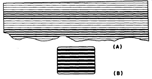
Fig. 2-12. How horizontal bars are formed in a tv raster by the presence of
a modulation signal of frequency lower than the horizontal-deflection frequency.
The negative portion of each modulation cycle blanks the beam for several horizontal
lines.
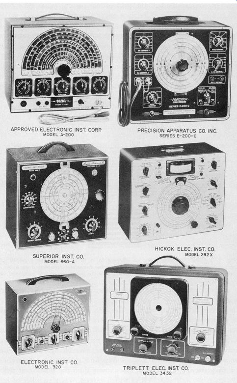
Fig. 2-13. Photographs of typical, modern a-m signal generators.
Note---The above photo, are reproduced through the courtesy of the manufacturers indicated.
Suppose now that the modulation frequency of our generator is variable, and that we gradually reduce the modulation frequency. As it is lowered to a frequency which is such as to produce 11 cycles during one scanning line, we see 11 vertical bars, 10 cycles produces 10 vertical bars, and so on, until we reach the horizontal deflection frequency of 15.75 khz, when there will be only one vertical bar. Now if we lower the modulation frequency still further, the bars change from vertical to horizontal. The reason for this is shown by Fig. 2-12. A modulation signal of a frequency that is several times lower than the horizontal deflection frequency has individual cycles which extend over a number of horizontal scanning lines. Consequently, at least several lines are blanked out at a time, thus giving the effect of horizontal bars. The number of bars may be changed by varying the frequency of the modulating signal.
Now if the signal generator carrier is modulated by both the high and low frequency signals at the same time, both horizontal and vertical bars appear, and the instrument becomes a cross-hatch generator.
The same effects can be obtained if the modulation signal alone is fed into the video amplifier of the tv receiver, simulating the condition when the modulated r-f signal is demodulated in the previously described process.