5-1. Range
In Section 1, we discussed the frequency ranges of various types of instruments. It is naturally desirable that as much of a frequency range as possible be included in each instrument. However, if a generator is to be reasonably priced, there is a limit to the range which can be provided. Tuning systems for the oscillator frequency have a limited cover age, and the number of ranges must not exceed that which is feasible in wiring and switching. Therefore, attempt is seldom made to provide a "universal" frequency coverage, but the range is planned for certain specific applications. Most generators are designed for radio and tv receiver alignment, testing, and design. However, incidental to their primary design purposes, they find many other varied applications, some of which are reviewed in Section 10.
5-2. Calibration
Most dial calibrations are simple, straightforward, and more or less self-explanatory. In most models, all ranges are calibrated on the same dial, with a selector switch to choose the desired range. In most general coverage a-m generators, as many as seven or eight ranges may be necessary to cover all frequencies included. If the dial is circular, these ranges are ordinarily calibrated in concentric circles.
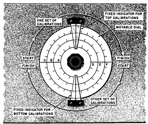
Fig. 5-1. When a circular dial is used, and the total range is covered in
180 degrees or IN, of rotation, two sets of scales can be available, one set
in the upper portion and the other set in the lower portion. This is illustrated
by the dial shown here.
If the full range of the tuning capacitor is covered in 180 degrees of rotation or less, two sets of scales are sometimes placed on one circular dial. This arrangement is illustrated in Fig. 5-1. Half of the ranges are placed on the top part of the dial and the other half on the lower portion. There is a separate indicator pointer mark for each set of calibrations. Some generators have the calibrations fixed on the panel and the index, or indicator mark, rotates over it, as shown in Fig. 5-2.
Not all dials and scales are of the circular type. Some are of the "slide-rule" type popular in many radio receivers. In others, the scale face is a revolving cylinder whose axis is vertical. This cylinder, with the calibrations marked on it, revolves past the vertical index marker on the generator panel. An example of such an arrangement is shown in Fig. 3-7.
5-3. Verniers
A vernier is a device for either indicating, or allowing setting to, given values of dial settings with greater accuracy than is possible with an ordinary dial. If the electronic system is stable, very good accuracy of frequency indications is obtained.
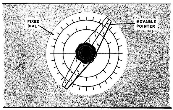
Fig. 5-2. With some generators, the calibration scale is stationery, while
the index mark revolves over it, as shown here. The revolving pointer is made
of dear plastic.
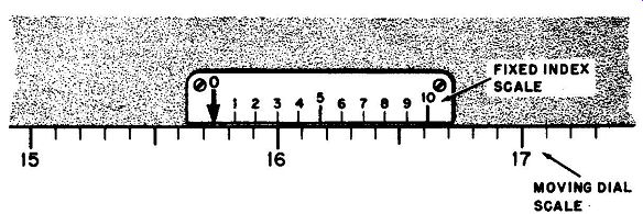
Fig. 5-3. Diagram showing how a vernier is used to indicate small changes
in dial reading.
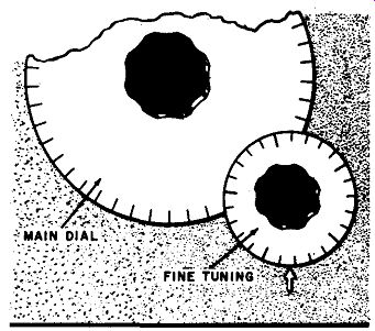
Fig. 5-4. How o fine tuning control is added to the dial in some generators,
to provide a means of indicating small increments of r-f oscillator frequency.
This is particularly useful in making selectivity measurements.
The vernier was originated by the French mathematician Pierre Vernier in the 17th century. A typical vernier scale drawn on a horizontal base is shown in Fig. 5-3. The fixed index indicator, instead of being just a single vertical line, is a series of l l vertical lines, calibrated from 0 to 10 inclusive. In its use, we first set the dial to approximately the frequency desired (or read it as already set) by use of the 0 (zero) mark used as an ordinary index, as on ordinary dial arrangements. Then, the one fixed index line that aligns itself exactly with a main dial calibration line shows how many tenths of a main dial calibration we are set above the previous calibration line. For example, in Fig. 5-3, the zero index line is showing that we are set for something between 15.7 and 15.8, but the second decimal place is not clear. We then note that on the fixed index scale the line marked "3" aligns itself exactly with a line on the main scale below. This shows that the exact, correct reading is 15.73. If the main scale is moved a little bit to the left (say 1/10 of a small division), line 3 will no longer be aligned and line 4 will become aligned with the main scale division line nearest it. Under these conditions, the reading is 15.74. Which of the main scale divisions aligns itself with the index line involved in each case is of no consequence.
Of course, verniers do not have to be straight and horizontal. The one shown in Fig. 5-3 is drawn this way only for the sake of simplicity and clarity. Actually, in practice, most verniers are curved and used in conjunction with a circular scale, but the principle is exactly the same.
Although the system just described is the true vernier system, other devices are often loosely referred to as "verniers." This name has in fact been used for almost any arrangement in which a knob is mechanically coupled to the main shaft so as to turn the latter more slowly than if it were turned directly. It is then easier to set the dial for a given frequency or to turn it slowly for certain tests where this is an advantage.
A few a-m generators have a calibrated fine tuning knob, such as is illustrated in Fig. 5-4. This may be calibrated in percent frequency change, as in such laboratory generators as the General Radio 605B. One of the most important uses of such an arrangement is in checking selectivity. The main dial of a generator cannot be designed to indicate a few kilocycles variation, especially at short-wave frequencies. In the use of the calibrated fine tuning knob of Fig. 5-4, we set the generator for center frequency as checked by the receiver dial. Then we set the generator attenuator for a good reference level output from the receiver, making sure that ave action is not present or is negligible. Next the step attenuator is advanced to give 10 times the voltage output; the generator frequency is then changed by means of the fine tuning dial until the receiver output is reduced to the original value. The frequency change indicated by the fine tuning dial indicates the "10-times-down" deviation on the selectivity curve, or half the 10-times-down bandwidth. Fine tuning calibrated dials are also useful for such things as frequency drift checking.
5-4. Frequency Drift and Warm-up
No oscillator is absolutely stable, and signal generator r-f oscillators are no exception. Even crystal-controlled oscillators have a definite drift characteristic, although their drift is negligible compared to all but the most carefully designed self-excited oscillators. Drift is mainly due to temperature effects. It is therefore most apparent when the generator is cold and has just been turned on. The heat dissipated in the tubes, transformers, and resistors is gradually transferred through the unit, ...
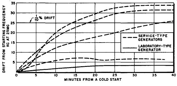
Fig. 5-5. Graph showing the extent of generator drill during warm-up period.
... warming up the oscillator components. For this reason it can be expected that, even in the best of generators, some frequency drift will inevitably occur in the first few minutes after the unit is turned on if it has not been used for a while. That is why one of the cardinal rules of signal generator use is: Always allow the generator to warm up for from 20 minutes to a half hour before using it for any applications in which frequency is important.
To illustrate the effect of warm-up, Fig. 5-5 shows the warm-up frequency characteristics of several service-type generators and one laboratory type. These characteristics are merely spot checks, but they do give a rough idea of the order of magnitude of frequency change usually involved.
Manufacturers of signal generators try to minimize drift as much as possible. Of course the extent of the measures they can afford to take varies with the ultimate cost of the unit; thus the higher priced laboratory precision types can be expected to be much more stable than the moderately priced service types, as is indicated by Fig. 5-5.
The method of design of oscillators for stability usually involves de signing the oscillator circuit and components for best inherent stability consistent with cost, then adding compensation in the form of negative temperature coefficient capacitors and similar devices. However, such compensation is difficult to maintain over a large frequency range, so generators with a great frequency coverage may be expected to have slightly worse drift in some portions of the range than comparable generators with a smaller range.
It can be seen from the characteristics shown in Fig. 5-5 that about a half hour warm-up is sufficient to reach the "leveling-off" condition for most types of generators. After this, the unit has usually about reached thermal equilibrium, and further changes in frequency due to temperature change are relatively small.
5-5. Effect of Voltage on Frequency
Another factor which may cause instability of the r-f oscillator is the applied voltage. In most oscillators, there is a definite effect of line voltage changes on oscillator frequency. For this reason, if line voltage is likely to fluctuate, it is important to take this into account, or to provide some means of voltage regulation. In a few of the higher priced generators, a voltage regulator is provided for the plate and screen voltages of the oscillator. This practically eliminates line voltage fluctuation effects within a voltage range of about ± 10 percent. However, a large number of generators do not include this feature, and the reader is urged to investigate the performance of his generator with line voltage changes and take them into account. Without voltage regulation, frequency changes with a 10 percent line voltage variation may be as high or higher than 0.1 percent, or 25 khz at 25 mhz.
5-6. Effect of Controls on Frequency
Because of the critical nature of stray capacitance and inductance effects, especially at high frequencies, it is natural that we often encounter variations of carrier frequency with control adjustments. This is particularly true of the continuously variable attenuator. Adjustment of this control in various signal generator models has resulted in a frequency shift of as high as 50 khz at 25 mhz in extreme cases, although the average is about 10 khz. At higher frequencies, a somewhat greater percentage of change can he expected, and at lower frequencies, a somewhat lower percentage. Other controls, such as meter setters, width controls, etc., may also affect frequency considerably.
If the variation of frequency involved is important in the tests being made, such control effects must he checked each time an adjustment is made. It is a good idea for the owner of any signal generator to make tests as to just what the effects of the controls are on the output frequency at various carrier frequencies. He will then know what to expect in any given test, and know whether he must correct for such variations or not.
5-7. Center Frequencies in Sweep Generators
In most sweep generators, the variations of frequency due to the factors previously discussed (temperature, voltage, and controls) is negligible compared to the sweep width. For example, sweep generators designed for tv receiver analysis have a sweep width of at least 10 mhz.
Even an extreme variation of 100 khz would hardly be noticeable. The sweep width is purposely adjusted to extend a megacycle or more beyond the actual response curve width; the frequency drift or variation of 100 khz would merely shift the response curve very slightly along the horizontal axis. In sweep generators designed for f-m receiver analysis, the sweep width is in the order of 500 khz to 1 mhz. Consequently, frequency fluctuation may be more noticeable if very severe, but can hardly be considered a serious problem, since in these generators sweep center frequency is nearly always readily adjustable.
In any kind of sweep analysis, markers are required. The marker indications show immediately when the sweep generator's center frequency has drifted. This, of course, emphasizes the importance of extra good stability for the marker frequencies, and it is in marker generators that drift must he carefully controlled.