7-1. Why Generators are Designed for Low-Impedance Output
In the use of a signal generator, especially where output voltages are to be measured, it is desirable to have the source (generator) impedance as low as possible. This is so that the voltage regulation of the generator output will be as good as possible. The ideal situation is that in which a low-impedance generator is connected to a very high impedance load; appreciable change in load resistance will then not affect generator output voltage.
Accordingly, most signal generators have output impedances of from 30 to 300 ohms. For high frequency a-m generators (above 20 mhz) and vhf sweep generators, the output impedance is often chosen to match the characteristic impedance of the line used in the connecting lead. As we shall see, it is important to do this, especially where wide ranges of frequencies are involved.
Another important reason for the use of low impedance for the output circuit is the effect of stray capacitance at radio frequencies. If a high impedance were used, stray capacitances between leads and between leads and ground would all become serious problems.
For example, a stray capacitance of only 1 µµf has a reactance value at 100 mhz of only about 1,600 ohms. If the output impedance were, say 2,000 or 5,000 ohms, it can be seen that almost any tiny stray capacitance would have a considerable loading effect and would tend to throw output voltage readings off and produce considerable instability.
7-2. Output Termination
To maintain proper output voltage indication and preserve stability, it is important that the lead from the signal generator be terminated properly. This termination is important not only from the standpoint of the generator operation, but also from the standpoint of the device being tested. In many cases the device to which the generator is connected must "see", in the generator lead, the impedance for which it is designed in normal operation. If the device is a radio receiver, and the generator is to be coupled to the antenna circuit, the generator lead, or an auxiliary circuit used with it, must exhibit to the receiver input circuit the same impedance as the antenna for which the receiver was designed. In most f-m and tv receivers this impedance is 300 ohms. In some tv receivers it is 72 ohms. For broadcast and all-wave type a-m receivers, a standard "dummy antenna" may have to he used.
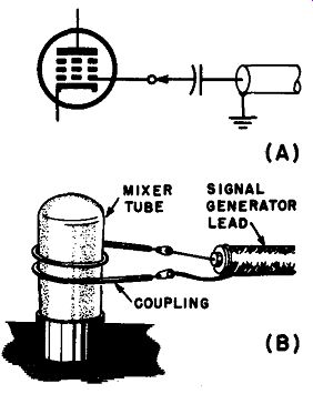
Fig. 7-1. Two ways of applying the low impedance of the signal generator output
to a high-impedance circuit, when if is not necessary to know from signal generator
indications how much is the input voltage to the circuit.
When feeding into the grid of a vacuum tube or other very high impedance device, some arrangement must he made to prevent the low impedance of the generator from shunting the input circuit of the tube.
Two ways in which this can be accomplished if the measurement of the generator output voltage is not important are shown in Fig. 7-1. At (A), a small value capacitor is connected in series with the generator lead to the receiver grid. The value of capacitance used must be small so that it will have a relatively large impedance at the frequency at which the tests are being made. In many cases a capacitance as low as 1 or 2 µ.µ.f is sufficient; for low-frequency receivers, such as the a-m broadcast type, 50 µ.µ.f or more may he necessary. Frequently, it is only necessary to clip the hot lead of the signal generator to an insulated lead or other insulated component that is connected to the grid of the tube to which coupling is to occur.
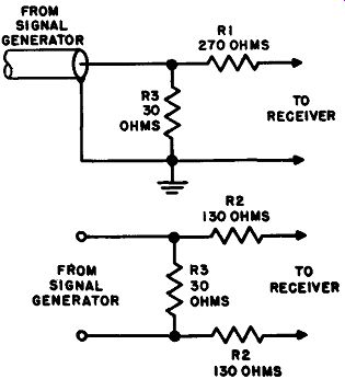
Fig. 7-2. Two ways of terminating signal generator leads to offer the desired
impedance to the device tested while maintaining proper impedance load to the
generator itself.
At (B) is shown another popular method of loosely coupling the generator to a circuit of a radio or tv receiver. A loop of wire is formed, with about two or three turns, by wrapping a wire around the tube into whose circuit the signal is to be injected. The wire should preferably be insulated. The ends of the wire loop are connected to the two leads from the signal generator. The loop is then slipped over the tube and the signal is injected into the tube by capacitive and inductive coupling.
It may also be possible to simply wrap the end of the hot lead of the signal generator around the tube envelope to produce this same effect.
If absolute voltage measurements are to be made from indications on the generator meter and attenuators, the above methods will not do.
Two methods of terminating with resistors to provide proper load for both signal generator and tested device are shown in Fig. 7-2. Each provides for a signal generator load of 30 ohms and a load on the receiver or other device of about 300 ohms. For feeding into larger resistances, resistors RI and R2 are made high enough in resistance so the output adds up to the desired resistance, while the 30-ohm resistor remains the same to keep the signal generator load constant. If the signal generator is designed for a higher output impedance, such as 72 ohms or 100 ohms, R3 is chosen accordingly, to match it.
7-3. Balanced and Unbalanced Circuits
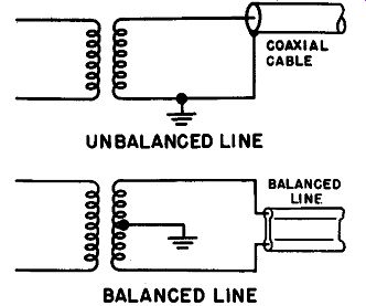
Fig. 7-3. Difference between balanced and unbalanced lines.
The output circuit of practically all signal generators is an unbalanced or single-ended circuit. This simply means that one lead of the output is grounded. The grounded lead is often referred to as the "ground lead" and the other lead as the "hot lead." The advantage of such a circuit is that it can be connected to a coaxial transmission line consisting of an inner conductor surrounded by a shield of metal braid with low-loss insulation between. The advantage of transmitting r-f current this way is that the shield can act as the ground lead, shielding the inner conductor, which is above ground. This prevents radiation from the lead, since electromagnetic radiation is stopped by a grounded shield in its path.
Sometimes another type of circuit is used for r-f energy -- the balanced circuit. In this circuit both leads are above ground by the same potential and the currents in these leads are 180 degrees. out of phase with each other. The balanced circuit is sometimes referred to as a "push-pull" circuit. The difference between an unbalanced and a balanced circuit is shown in Fig. 7-3. Balanced circuits may also be shielded to prevent radiation.
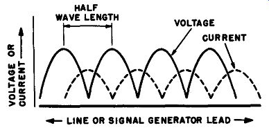
Fig. 7-4. How the voltage and current is distributed along a trans mission
line when there ore standing waves.
7-4. Standing Waves
At high frequencies, especially in the vhf and uhf ranges, standing waves may become a problem in signal generator leads. In order to understand this phenomenon, we must review very briefly how it comes about.
Standing-wave problems become important when the length of a transmission line is an appreciable fraction of a wavelength at the frequency of the signal it is to transmit.
For example, consider the wavelength of signals at two different frequencies, one in the a-m broadcast band, and the other in the vhf range (in the f-m broadcast band): 1,000 khz wavelength - 300 meters, or about 1,000 feet 100 mhz wavelength - 3 meters, or about 10 feet
Note that at 1,000 khz a 3-foot signal generator lead is a very small fraction of the 1,000-foot wavelength. At 100 mhz, however, the 3-foot lead is about one-third of the wavelength. In the latter case the problem of standing waves may become severe.
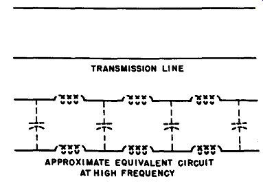
Fig. 7-5. At high frequencies, a transmission line is equivalent to a series
of inductances and capacitances blended together into "distributed constants."
Standing waves result on a transmission line when part of the energy of the signal that is sent along the line is reflected from the receiving end of the line back toward the sending end. The transmitted signal and the reflected signal combine; at some points they are in phase and the current is large; at other points they are in phase opposition and the current is low. The same thing happens with voltage, except that the voltage maxima and minima are at points one-quarter wavelength away from the current maxima and minima. Figure 7-4 shows a graphical indication of the voltage and current along a line with standing waves.
One of the most mystifying factors about standing waves to the beginner is the fact that the current along a line which is not connected to anything else can change, since in d-c circuits this can never happen.
Actually, as illustrated in Fig. 7-5, there is something "connected" to the line in a sense. A signal generator lead has appreciable capacitance between conductors and appreciable inductance along its length. They are called the "distributed constants" of the line. The capacitance shunts the line and draws current across it; the inductance keeps shifting the phase of this current as we go along the line. If the end of the lead is not properly loaded, both the current and the voltage of the line change and there are standing waves.
There is one basic way in which standing waves can be eliminated from a line; that is by "matching" the line. Each transmission line has a constant, called its characteristic impedance or sometimes its surge impedance. Its value depends upon the physical characteristics of the line. For coaxial cable, the characteristic impedance of some is 50 ohms, for most types it is 72 ohms. Ribbon or twin lead open-wire lines are available in various values of impedance, from 72 ohms up to 300 ohms.
Other types of open-wire lines may run as high as 800 or 1,000 ohms.
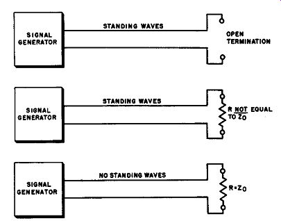
Fig. 7-6. Standing waves con be eliminated by terminating a line in its own
characteristic.
Standing waves can be eliminated from a transmission line if the line is terminated in its own characteristic impedance, as illustrated in Fig. 7-6. In other words, a line is said to be perfectly "matched" and its standing waves are eliminated when the impedance of the source at the sending end and the load at the receiving end are both equal to the characteristic impedance. The characteristic impedance is a pure resistance, without reactance.
In studying the construction of signal generators themselves, we are primarily interested in the shielded types of line which would be used for connecting leads. There are two main types. The more common type is the simple coaxial cable, in which a single conductor surrounded by low-loss insulation is centered inside a copper-braid shield. This cable thus forms an unbalanced circuit. In another type of shielded lead, two inner conductors are used, both insulated from, and enclosed by the shield braid. This forms a balanced circuit against the shield ground. Nearly all signal generators use the simple unbalanced line; when balanced output is required, they have a special lead to convert the unbalanced output to balanced at the end of the lead, as will presently be explained.
7-5. Effect of Standing Waves on Signal Generator Performance
It has been explained that standing waves consist of a series of high voltage and low voltage, and high current and low current points along a transmission line such as the lead from a high frequency signal generator. The distribution of standing waves along a line is shown in Fig. 7-4. Places where voltage is a maximum are called voltage loops, and where voltage is a minimum, voltage nodes. In the same way, current maxima and minima are respectively called current loops and current nodes. Successive voltage loops are spaced one-half wavelength apart along the line; successive voltage nodes are also one-half wavelength apart but are located midway between the voltage loops. Therefore, adjacent pairs of voltage loops and nodes are spaced one-quarter wave apart. Wherever there is a voltage loop, there is a current node; where there is a voltage node there is a current loop.
Because standing waves are spaced in terms of wavelength, their position changes along the line as frequency is changed, so their particular location is not predictable except for one particular frequency, or with complicated calculations. At a voltage loop, the voltage may be many times that which would normally be present if there were no standing waves. Thus the generator output voltage may vary through wide ranges as frequency is changed if there are standing waves present.
Standing waves are particularly troublesome with sweep generators operating in the vhf region, because as the frequency sweeps through its range, the output voltage changes radically. The result is that the sweep amplitude is variable, and the voltage applied to the device whose response is to be observed is not constant through the sweep range.
This naturally affects the apparent shape of the response curve greatly, producing spurious peaks and valleys and giving other misleading results.
The reflections in the lead also give trouble, causing double trace lines and difficulty in obtaining a sharp stable image. In addition, when standing waves exist, the output lead is very "touchy" and is very sensitive to changes in position and connection. Standing waves may even exist on the outside of shielded cable so that the output of the generator varies as the cable is touched and as the hand is moved along the length of the lead. As we have mentioned before, the way to eliminate standing waves is to terminate the lead in its own characteristic impedance.
There are a number of ways of doing this. We shall consider several in the next section.
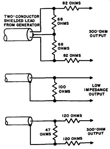
Fig. 7-7. A few typical methods for terminating signal-generator leads. Some
are these included in the generator leads; others are recommended by manufacturers
as external additions.
7-6. Types of leads Used for Signal Generator Output
We have now established that the output lead and its termination must:
1. Provide a proper load for the generator, so its output voltage is stabilized and properly indicated.
2. Provide a proper load equivalent to the characteristic impedance of the lead line, especially at high frequencies, to minimize standing waves.
3. Exhibit to the device an impedance which will reasonably approximate its normal operation, so that tests made on it will have a practical meaning.
At frequencies below about 20 or 30 mhz, standing waves are not likely to be a factor. Line losses are not appreciable, so ordinary shielded wire is commonly used for the leads. At higher frequencies (or for generators whose range extends into the vhf and uhf regions) coaxial cable is most frequently used.
Sometimes a terminating network is connected right into the end of the lead, and sometimes the lead has no self-contained termination.
In the latter case it is expected that the operator will add whatever termination is necessary externally. Two typical terminating arrangements are illustrated in Fig. 7-2.
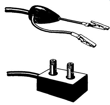
Fig. 7-8. Two way, of making connection from the end of the signal-generator
lead to the device to be tested.
It should be pointed out here that each signal generator model may be somewhat different from other models. The type of termination best for each purpose in each case is likely to be a little different. The ultimate authority on this subject is, of course, the manufacturer of the generator. The reader is, therefore, urged to consult the manufacturer's instruction manual for a signal generator before he attempts termination himself. These instruction manuals usually provide much data on the ways in which the output leads can be adapted to different purposes and will frequently show the details of the lead construction for their models.
The following information is given to provide examples and as a guide when no other data are available, but should not be substituted for specific information in the manufacturer's instruction book.
A number of typical terminating networks are illustrated in Fig. 7-7.
These are arrangements which are given in signal generator manufacturers' instruction books and include both circuits included in the generator lead and others recommended to the user of the generator as an addition. Note the idea is always about the same as that previously set forth in Fig. 7-2, that is, to present to the generator and the device being tested their proper load impedances.
The termination end of the signal generator lead used is most commonly equipped with dips to facilitate connection to the receiver or other device being checked. Another variation is a pair of binding posts mounted at the end of the load. Two typical arrangements are shown in Fig. 7-8. Sometimes it is desirable to connect a balanced output lead which the test equipment manufacturer has provided for a 300-ohm load to an unbalanced circuit. A typical arrangement for doing this is illustrated in Fig. 7-9. The output between one conductor and ground is used, while the other "side" of the circuit between the other hot lead and ground must be terminated in its impedance, in this case, 150 ohms.
Note that when the 75-ohm load is connected, the other "side" of the circuit is also terminated in 150 ohms.
At the generator end, the lead is usually terminated in either a standard microphone connector or a phone plug, whichever is necessary to match the connector on the generator itself. If the lead is for balanced output, a two-conductor shielded type connector is necessary.
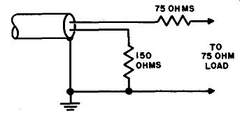
Fig. 7-9. Arrangement far adapting balanced 300-ahm output lo match 75-ohm
circuit.
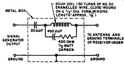
Fig. 7-10. Standard dummy antenna circuit for coupling the signal generator
to an a-m receiver to match the receiver input over a wide range of frequencies.
7-7. Dummy Antennas
A dummy antenna is a device used to connect a load or generator to a receiver or transmitter to provide rated load resistance or impedance during tests or measurements. For signal generators a dummy antenna is a device used to couple the generator to the antenna circuit of a receiver in such a way that the impedance offered to that circuit is the same as that offered by an actual antenna, or the antenna for which it was designed. Actually all the terminating devices so far discussed qualify to be called dummy antennas if used with receivers.
For use with a-m receivers operating from 550 khz through 30 mhz or so, a standard dummy antenna has been adopted and recommended by the Institute of Radio Engineers. The circuit of this dummy antenna is given in Fig. 7-10. It offers an impedance to the receiver which is a good average approximating that of a-m receiving antennas in general.
At the short-wave frequencies it is equivalent to the receiver end of a matched 400-ohm transmission line. Consequently, the dummy antenna provides an impedance to the input of the receiver which is the same as that which might be expected in practice, so that tests and alignment adjustments will be proper. Otherwise, adjustments in the input circuit, without proper antenna impedance connected, might be wrong under actual conditions.
An alternative dummy antenna suitable for tests only in the a-m broadcast band is shown in Fig. 7-11. This offers the same impedance as the circuit of Fig. 7-10 in the a-m broadcast range. The IRE has the following to say about the construction of the dummy antenna: The stray capacitance between any two points must be so small as to be negligible at operating frequencies, and the dummy antenna must be so devised as to avoid coupling to other equipment .... The leads used in connecting the signal generator through the dummy antenna to the receiver should be short so as to introduce negligible voltage drop.
They should be shielded to reduce external fields.
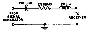
Fig. 7-11. Alternative dummy antenna circuit for a-m broadcast receivers only.
7-8. Importance of Shielding in General
--------------------
• IRE Standards - Methods of Testing Amplitude .Modulation Broadcast Receivers, 1948, 3.02.02
-------------------
From time to time in our previous discussions, we have mentioned the importance of shielding. Probably no other electronic device requires the degree of shielding needed by the highest quality types of signal generators. The reason the generator itself must be shielded is to avoid leakage and radiation, which prevent attenuation of the external signal to low values of output. Another reason for shielding of the unit is that both output voltage and frequency can be affected by external objects if shielding is not present. The operator's body can introduce stray capacitance and loading effects which will cause both amplitude and frequency to vary as he moves around near the generator. In addition, lack of shielding can cause pick-up of energy from external fields, particularly power-line hum. This hum can modulate the signal and cause other troubles, if there is not sufficient shielding. Radiation of the signal directly from the generator can cause it to be picked up on power cords, connecting leads, telephone leads, and other wiring.
As was previously explained, the degree of perfection of the shielding of the signal generator used depends upon the type of instrument and its requirements in practice. A very low-cost generator designed only for a-m broadcast receiver testing would not be expected to have very elaborate shielding. On the other hand, precision laboratory types for vhf and uhf ranges will be shielded with great care. Thick copper shielding material is ordinarily used in the latter, with both the individual sections inside and the whole unit completely enclosed. Leads are passed through shield partitions only in shielded connectors, and there is plenty of bypassing at all strategic points. An elaborate line filter is also usually installed. When such measures are employed, it is often possible to set the generator for a small fraction of a microvolt output without experiencing any serious radiation.
In other generators for purposes with less rigid requirements (such as ordinary radio and tv receiver servicing) the shielding may not be so elaborate, since it is seldom necessary to drop below 25 to 100 microvolts.
In the use of sweep generators for tv receiver response analysis, it is difficult to obtain a good response picture if the shielding of the generator is not quite good, and if this shielding is not properly grounded.
Besides the signal generator unit itself, all leads to and from it must be shielded (or filtered) or the shielding of the unit itself will be to no avail. That is why shielded leads of the type described in Section 7-6 are used. In many of the more elaborate laboratory types the power-line lead to the generator is also shielded, with a line filter inside the unit.
The shield braid is connected to the chassis-cabinet of the unit and may be connected into a polarized plug at the other end, if such a plug is used. Otherwise, there may be a short clip lead protruding from the plug end of the power cord, to be clipped to the nearest ground connection.
Most of the problems concerning shielding arise when low signal voltages are to be used. This is quite often so with sensitive receivers, since it is desirable to keep the signal intensity to as low a value as possible and still obtain a useful signal. ·when receivers are tested at very low signal levels, or in areas where external signals are strong, interference from such external signals from other signal generators and from local broadcast stations may become severe. For this reason a shielded room is often used. Ordinarily this consists of a room completely surrounded by wire netting or screening of some kind. Sometimes one or more of the walls is lined with metal plate. The door to the room is also completely covered with the shielding material, and provisions are made so that when it is closed, the shielding on the door and that on the remainder of the room become electrically continuous. The signal generator, the receiver to be tested, and any other equipment necessary is set up on a bench inside the shielded room. Power-line leads into the room must be filtered and shielded. The operator and his equipment are thus completely enclosed in a large metal box, which prevents external signals from interfering with tests in progress. Shielded rooms are used primarily in cases where very exacting testing, design, and development work are necessary. Most receiver manufacturers and electronic testing laboratories are so equipped.
7-9. Grounding
Shielding and grounding usually go together. In fact, all the measures explained for shielding in Section 7-8 would be useless if all the shielding were not grounded.
Because there is a large metal cabinet around a unit, this does not necessarily mean that the cabinet is at ground potential. We must make sure it is securely grounded. Otherwise points which are supposed to.
be at ground potential will actually develop an r-f voltage above ground and interfere with the effectiveness and accuracy of any tests being made.
Most grounding trouble arises because of the fact that an ordinary straight wire has some inductance and some resistance. Even though these values are small, their effects may become very great at radio frequencies, especially the higher radio frequencies. The resistance of a piece of wire rises as frequency increases. This is due to a phenomenon called skin effect. The higher the frequency, the more the current tends to flow only in the outer surface of the wire, thus increasing its effective resistance because only a small part of the conducting material is used.
For example, a wire about 40 mils in diameter has, at 100 mhz, 35 times its resistance to direct current.
Both the inductance and the r-f resistance of a wire decrease as the diameter of the wire is increased. The decrease in r-f resistance is not as great as its decrease in d-c resistance, but it is a definite decrease.
For this reason, it is important that the ground connections used be made with large diameter wire to be sure that an r-f potential does not build up between the supposedly grounded point and true ground.
The reference point for true ground is usually considered to be the earth itself. Since often the testing area in which the generator is used is considerably above the earth, obtaining a direct ground may be a problem. However, usually a water pipe is satisfactory for most moderate and low frequencies, since it travels underground and thus makes good contact with the earth. Copper piping is naturally better than iron piping, because of the much better conductivity.
It is desirable that in the location in which a generator is to be used for some time, and when rather exacting tests are to be made, a good low-impedance ground connection be arranged for. If a water pipe runs nearby, a heavy wire lead of about #8 or larger should be run from a heavy clamp attached to the pipe, to a convenient connecting point on the test bench. Even better than heavy wire is shield braid about one inch wide; this has low inductance and resistance at high frequencies and is often used in exacting grounding requirements.
Where the distance between true earth ground and the testing point is rather great, no ground can be really good for vhf and uhf testing.
There is then no point in doing more than the normal things required for a good ground at lower frequencies.
The importance at these frequencies then shifts to ensuring that everything is connected to a common grounding point. Then even if the grounding point is somewhat above ground to r-f, the fact that each unit in the system is shielded .and grounded at a common potential will be satisfactory. To do this it is suggested that the units all be connected to a solid copper strip, bar, pipe, or rod, which runs along the bench and is grounded to the best available ground.
Another very useful way of maintaining a good common ground, especially for testing radio and tv receivers, is the use of a ground plate.
This is simply a sheet of metal, preferably copper, which covers the whole working area of the top of the test bench. The signal generator, the receiver, and any other equipment are then placed on this metal sheet.
If the chassis is clean and rests directly upon the metal for each unit, everything will be automatically grounded; otherwise means must be used for providing a direct ground from each chassis to the metal plate.
The ground plate not only establishes a common ground potential, but tends to provide shielding against interference effects.
The ground plate should not be considered a substitute for a good ground; it is merely an extension of a good ground and must be itself a good ground to be effective.
Another important factor about grounds is that each unit to be grounded through wires should be grounded separately. That is, if three units are to be grounded, run a good ground wire from each unit to a common connecting point, rather than from one unit to another, then to the next, then to ground. This minimizes the build-up of r-f voltages between units.