6-1. Range of Output Voltage
The output voltage capabilities of various types of signal generators fall into one generator range, namely, from roughly zero to either 10,000 or 100,000 microvolts. This voltage is what is obtainable from the regular output lead, with normal attenuator control. In many generators, an additional output jack is provided from which a voltage in the order of 1 volt or more is obtainable. The latter is usually from a connection on the oscillator side of the step attenuator, so it represents voltage more or less directly from the oscillator. The high output jack is intended primarily for cases in which a radio receiver may be far out of alignment, and can be used until the alignment adjustments are near enough so that the normal output jack can be used. Generally, better stability and control can be expected when the lower voltage from the normal jack is used.
6-2. Attenuators
The purpose and function of attenuators have already been considered (Sections 2-2 and 2-4). There are two types used in generators: the continuous type and the step type. The continuous type is ordinarily just a potentiometer connected across the r-f oscillator output, with the variable tap connected to the output jack, or to the step attenuator, if there is one. Its function is just like that of the volume control of an ordinary superheterodyne receiver, except that here the intensity of r-f voltage instead of a-f voltage is being controlled. If a step attenuator follows, the continuous attenuator controls the input voltage to the step attenuator; the latter controls the maximum voltage at any position, usually in steps of 10.
In step attenuators, the design is such as to attempt to maintain a constant output impedance while the output voltage is varied in the "times-10" steps. A typical example of a circuit that will do this is shown in Fig. 6-1. This diagram shows both the continuous and step-type attenuators used together. Note that the continuous attenuator varies the voltage applied to the input of the step attenuator. At each step of the step attenuator, an output impedance of about 33 ohms is maintained.
The step attenuator network used here is often referred to as a "ladder" network, because of the way in which the resistors are arranged.
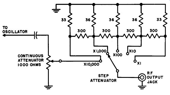
Fig. 6-1. Typical combination continuous and step attenuator circuit for a
signal generator.
As the step attenuator switch is moved from the "X1" toward the "X 10,000" position, the output signal voltage increases in steps of 10. Occasionally, the markings on the step attenuator are just the opposite to that shown in the figure; that is, the signal output is reduced as the setting is changed from "X 1" to a "X 10,000" position. In this case, the markings indicate the amount of signal attenuation or reduction of signal strength rather than the amount of output signal.
One of the problems of attenuators is leakage. For instance, consider again the circuit of Fig. 6-1. If all these resistors are simply connected inside the generator cabinet without any shielding, the r-f voltage from the oscillator and from the lead at the high-voltage end of the continuous attenuator would be coupled through stray capacitance to the low voltage (X1) end of the step attenuator. The r-f voltage picked up on the two lowest positions (X1 and X 10) may then easily be many times the r-f voltage which is supposed to be there after the action of the attenuator. The result would be that the output voltage would not be affected, or at least not controlled below a minimum value for the attenuator's lowest positions. In the same way, the action of the continuous attenuator when adjusted for very low output voltage may be impaired.
R-f voltage can feed by capacitance coupling from the high end of the continuous control to the r-f output jack of the generator.
To avoid such direct leakage and impairment of attenuator action, attenuators are usually shielded, especially the step attenuator. A shield completely surrounds the entire step attenuator, while a separate shielded compartment is provided for the resistors in each step.
As has been previously explained (Section 2), the step attenuator is used to provide "jumps" of 10 to 1 in output voltage, and the continuous attenuator can be used to adjust voltages between attenuator steps. Often the continuous attenuator is referred to as the "microvolts" control, and it is then calibrated from 1 to 10 to represent microvolts.
For example, on a signal generator with a calibrated output, if the microvolts control reads 7, and the step attenuator is on the X 10 position, the output voltage is 7 x 10, or 70 microvolts. In many cases, the output attenuator is not accurately calibrated so that this control simply serves as a coarse adjustment of the level of the output signal.
6-3. Leakage
Theoretically, all the r-f voltage from the oscillator is applied to the attenuators, is properly adjusted by them, and appears at the end of the output lead for use. In practice, this is not strictly true. In fact one of the greatest problems of manufacturers and designers of signal generators is to keep r-f voltage from radiating, coupling, or conducting to places where it is not wanted, thus affecting the accuracy of adjustments and limiting use of the instrument.
Many a-m receivers have a sensitivity in the order of 1 microvolt.
That is, satisfactory reception can be obtained with an r-f voltage applied at the antenna terminals of only 1 microvolt. A very small, low-power oscillator, unshielded, will radiate enough r-f energy from a distance of hundreds of feet to be picked up by such a receiver. To prevent direct radiation from the oscillator in a signal generator to a sensitive receiver, extreme care in shielding of the generator is necessary. For this reason, most signal generators are enclosed in a tight fitting metal cabinet, and most of the individual components inside it are shielded separately.
Besides this, as has been explained in Section 6-2, the attenuators are also shielded carefully.
In the higher priced laboratory-type signal generators, the complete generator assembly is enclosed in heavy sheet copper, with individual components also shielded. The more conductive the shielding material, the more effective it is as an r-f shield. However, the service-type generator is ordinarily somewhat less critical, and steel, aluminum, or other types of metal cabinets and shielding are used.
From all except elaborate laboratory types, there should be expected some appreciable amount of leakage. For this reason, when testing with low signal voltages (from 1 to 100 microvolts), one should take all possible measures to overcome the leakage problem. One way to minimize it is to place the signal generator as far away from the receiver or other device to be tested as the generator output lead will allow.
However, never try to tamper with, or add to, the output leads sup plied by the manufacturer of the generator; the reason will be explained in Section 7. Another way to keep the effects of radiation and other leakage down, is through complete and proper grounding. This is also discussed further in Section 7.
The relative amount of leakage of a signal generator can be roughly determined if a sensitive receiver is available. Couple the signal generator leads to the receiver and connect an output meter to the receiver output circuit (or use the S-meter if the receiver has one). Now adjust the generator and receiver frequencies so that a signal is picked up by the receiver from the generator. If the receiver is of the high-frequency or short-wave type, the radiation effect is worse at the higher frequencies and should be tested there. Now gradually reduce the output of the signal generator, and with the receiver adjusted for maximum sensitivity try to make the signal disappear. Be sure to allow for frequency changes due to control adjustment and keep the signal always tuned in on the receiver. If there is appreciable leakage, a point will be reached at which the signal in the receiver is no longer reduced by lowering the attenuator control adjustment on the signal generator. This means that the receiver is picking up the signal by radiation, which remains constant, and is therefore not affected by voltage at the signal generator output jack. Of course the effectiveness of this experiment is also affected by the degree of shielding used in the receiver. Some communications receivers are so well shielded that direct radiation from the generator does not enter the receiver circuits. However, leakage in the generator to the output lead connection will still show up in even a well shielded receiver.
The above type of test will show quite a variety of degrees of radiation in different signal generators. In some cases, attempts to reduce input to the receiver of less than 100 microvolts fail. In the best laboratory signal generators, output from the leads can be reduced to a fraction of a microvolt before radiation effects are noticeable.
One important method by which leakage takes place in some signal generators is through the power line. The r-f current from the oscillator is coupled back through the power supply and into the power line. The r-f current in the a-c lead to the generator then acts as an antenna, and radiates the r-f signal to the receiver or the connecting leads from the generator to the receiver. For this reason, many of the more elaborate signal generators use line filters and some even employ shielded power leads.
6-4. Reducing Output Voltage by External Means
In some cases, when a sensitive receiver or similar device is to be tested or aligned, we may have difficulty with too much output voltage, due to the effects of radiation. As was explained above, this is most likely to occur when a lower priced type of generator and a sensitive, not-to-well shielded receiver are used. If we are not particularly interested in the value of the voltage applied to the device, but merely want the voltage for such an operation as alignment, the voltage can be reduced by external means.
One of the simplest ways to reduce signal which is excessive is to disconnect the signal generator from the receiver completely. If this does not provide enough reduction, simply start moving the signal generator away from the receiver until the desired intensity of received signal is reached. When only a signal of a given frequency and modulation type is required, and signal voltage need not be measured, there is no necessity at all for connecting the generator unless this is needed to obtain enough signal amplitude, or unless coupling must be accomplished to one specific point. It is not unusual to see someone completely align a sensitive a-m receiver with the generator on a bench ten feet away.
However, the moment we are concerned with either absolute or relative signal voltages at the receiver antenna terminals, we must have a direct, proper connection to the receiver. It is then that terminating and shielding become so important, as discussed further in Section 7.
Another way of providing reduced output in cases where output voltage is not to be an important factor, is by simply laying the leads against a tube or input circuit without a direct connection. Another way is to wrap the hot lead around the tube of the section in which the signal is to be injected. If a wire from the device to be tested and a wire from the hot lead of the generator are twisted together for a few inches (with one or both wires insulated), the coupling can be varied by twisting and untwisting these wires. All these methods apply primarily to cases in which the direct connection of the generator gives too much voltage, while completely disconnecting it gives too little voltage. Of course, a variable capacitor connected between the generator lead and the receiver input circuit can be used. How large the capacitor is depends upon the frequency and impedance into which the signal is fed. For radio receivers in general, at low frequencies, the capacitor should be several hundred micromicrofarads maximum. At frequencies from 20 mhz and up, a small 50- or 100-µµf capacitor should be sufficient.
6-5. Output Meters
It was explained in Section 2 that signal generators which are designed to indicate accurately their output voltage must have some kind of meter or other indicator so that variations in output due to temperature, humidity, and aging can be compensated for. The meter may indicate microvolts directly, or may indicate a reference mark or marks at which reading the attenuator and microvolts controls indicate output voltage. In either case, the meter is accompanied by a meter adjuster knob. This knob is adjusted to place the meter to the proper reference point or, with the microvolts type, to the desired voltage.
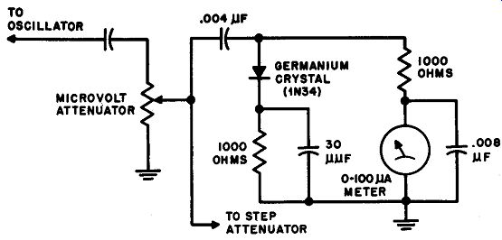
Fig. 6-2. Typical signal generator output voltage meter circuit.
Such a meter is either a vacuum-tube voltmeter or a sensitive d-c meter connected in a rectifier circuit with a crystal rectifier. The r-f output is rectified and actuates the meter, thus indicating the relative output voltage. A typical meter indicator circuit for a signal generator is shown in Fig. 6-2. The voltage which actuates the meter is obtained from the output of the continuous attenuator, which becomes the micro volts control. The step attenuator then follows both, and determines the multiplier, or ratio, between this voltage and the actual output value.
In some generators, rectification of the r-f output signal is followed by a d-c amplifier circuit which then actuates the meter.
6-6. Effect of Harmonic Content on Output Voltage
Normally the meter indicator circuit of a signal generator is not selective as far as frequency is concerned. That is, the voltage which actuates the meter is the total voltage output of the generator oscillator and continuous attenuator. If the oscillator output voltage contains an appreciable amount of harmonics, the meter measures the sum of all the harmonic components and the fundamental. In cases in which the fundamental signal from the generator is being used, the harmonics are not usually great enough in amplitude to affect the accuracy of voltage readings seriously. However, if we use a harmonic of the frequency at which the oscillator is working, voltage readings will not be at all indicative of the actual output at the frequency in use.
For example, suppose the signal generator covers only up to 20 mhz and we wish to use it for tests on a receiver at 30 mhz. We may do so by adjusting the generator to 15 mhz and using the second harmonic of the generator output. However any voltage indication on the generator will be in error. Say, for example, that the fundamental output voltage is about 1,000 microvolts. The second harmonic may be only about 10 percent of this, or about 100 microvolts, or even considerably less. What is more, the second, or other, harmonic component may vary consider ably in relative strength as the fundamental frequency is varied and as attenuators are changed. This fact should be kept in mind; voltage indications should not be used for harmonic operation.