AMAZON multi-meters discounts AMAZON oscilloscope discounts
17. Principles of Gas Tube Voltage Regulators
Referring back to Fig. 3, we see that a gaseous discharge in the normal-glow region possesses constant-voltage characteristics. The voltage drop across the conducting gas in the region from point D to point E does not vary materially even though the current changes over a wide range of values. Thus, as long as a cold cathode tube is working under the conditions which provide a normal glow, it will be found that the voltage across it will increase very little with a rise of current. Advantage may be taken of this characteristic by incorporating the gas two-element tube in a circuit which has the ability to hold the output d-c voltage constant under conditions of changing line voltage and changing load.
A fundamental regulator circuit using a cold-cathode diode is shown in Fig. 11. The 0C3 (VR-105/30) has been chosen as the regulator tube. The characteristics of this tube as given by the manufacturer are listed in the table below.
(1) Dc anode supply voltage (minimum) 133 volts
(2) Continuous dc operating current ........ 40 ma (max)
(3) Ambient temperature range ......... -55° to +90° C
(4) D-c starting voltage .......... 115 volts (approx.)
(5) D-c voltage drop across terminals (normal) .... 118 volts
(6) Regulation tolerance 5-40 ma) ......... average change in anode-cathode voltage 2 v (+ or -) maximum change 4 v
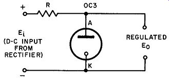
Fig. 11. A fundamental voltage-regulator circuit using a single gas tube.
To learn about the operation of the VR tube, examine these characteristics closely:
(1) The 0C3 (Fig. 12) will not break down into a self-maintained normal glow discharge until the voltage applied between its terminals is as least 115 volts (A to K). This 115 volts is an average value -- some tubes may break down at a lower value. This applied potential is generally known as the starting voltage. It is a function of the element spacing, element dimensions, gas material and gas pressure. Starting voltage is also a function of the ambient light level. The required breakdown must be larger when the tube is operated in darkness than in light. These tubes have, as an anode, a thin central post which lies along the axis of an encircling cylinder about 7/8 inch in diameter. The outer cylinder serves as the cathode. The circuit arrangement must be such that the initial voltage across both the resistor R and the VR tube is at least 133 volts to start the action. This voltage is necessary to insure breakdown throughout life. The average value required for new tubes is 115 volts.
(2) The cathode and anode dimensions of this particular voltage regulator permit a current of approximately 40 ma to flow with out excessive heating; hence, the tube can dissipate approximately 4-2 watts maximum. In normal use, a maximum current of 30 ma is usually recommended.
(3) The wide ambient temperature range shown implies that good voltage regulation does not depend to any great extent upon external temperature conditions.
(4) The dc starting voltage is the potential required between the anode and cathode to start the normal-glow discharge.
(5) Once the normal-glow discharge begins, the potential across the tube terminals drops to approximately 105 volts; this voltage is maintained throughout the normal-glow region over a wide range of currents (from 5 ma to 40 ma).
18. Circuit Action
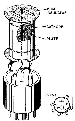
Fig. 12. Essential elements of a VR tube (0C3). RCA --- MICA INSULATOR CATHODE
PLATE
Variation of Line Voltage. Assume that the line voltage which feeds the rectifier-filter system tends to rise in value. As it does so, the d-c input voltage (E1, Fig. 11) increases causing an increased current in the series circuit consisting of R and the VR tube. increased ionization in the gas tube results in a lower internal resistance which, in turn, maintains the voltage across the tube at very close to the original value. The increased line voltage is absorbed in the form of a greater voltage drop across R (due to the increased series current). A fall of line potential has the opposite effect, resulting in a smaller drop across R, but the same voltage across the VR tube. The amount of change the line voltage may undergo is limited by the 5-40 ma rating of the tube; if the voltage is permitted to rise too high, the tube will overheat and eventually destroy it-self. Too low an applied voltage will cause the glow to extinguish so that the VR tube will then "look" like a virtually open circuit to the power supply and load. Under these conditions, there is no voltage regulation at all since the same situation may be simulated by removing the VR tube altogether. It is likewise possible that too low an applied voltage may also cause the current to drop below 5 ma without extinguishing the glow entirely. This causes erratic fluctuations in the output voltage.
Variation of Load. Consider a load whose resistance is such as to permit a current of 20 ma to flow through the VR tube. If the load resistance should now diminish, a greater current will flow through R causing a larger voltage drop to appear across it. Without the VR tube in the circuit, this would result in a proportionately smaller voltage across the load resistance, i.e. poor regulation. In this case, however, the increased voltage drop across the resistor leaves less voltage for the VR tube, thereby reducing the tube current. The resulting decrease in ionization increases the tube's resistance so that the same voltage drop appears across it (105 volts in this case). Thus, the load is still connected across 105 volts and the regulation is improved.
19. Design of a Voltage Regulator Circuit
Full appreciation of the action of a VR tube is best obtained by working through an illustrative example in the design of a VR circuit like that shown in Fig. 13.
Suppose that the figures given are these: (E1) Power supply variation: 250 v to 300 v (IL) Load current variation: 10 ma to 30 ma VR Tube: E0 150 volts regulated lvr = 30 ma max, 5 ma min.
E_min = 165 volts (starting voltage)
The problem is to determine the optimum value for the series resistor R. Step 1. Determine the resistance R when the input voltage E1 is largest and the load current is smallest (IL) . It is at this time that the VR tube would take the maximum allowable current. The current through R is the sum of Ivr and IL, or 30 ma plus 10 ma = 40 ma. At the same time, the input voltage E1 is 300 volts while the voltage drop across the VR tube must be 150 volts. Thus, the voltage drop across R = 300 - 150 = 150 volts.
From these values, R = 150/04 = 3,750 ohms
Step 2. Check to make certain that the VR tube current is not less than 5 ma when E1 is minimum (250 volts) and load current is maximum (20 ma). With E1 equal to 250 volts, the voltage drop across R = 250 - 150 = 100 volts. Then the current through both the VR tube and the load is 100/3750 = .027 amperes. With the load current given as 20 ma, the current left for the tube is .027 - .020 = .007 = 7 ma. This exceeds the minimum rating of 5 ma and is therefore acceptable.
Step 3. Check to determine whether or not starting voltage is obtained under the most adverse conditions: supply voltage Ei at a minimum (250 volts) and load current at a maximum (20 ma).
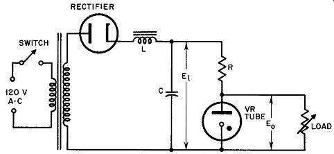
Fig. 13. VR tube design circuit.
With the supply voltage equal to 250 volts, the voltage across the resistor (with the VR tube in the nonconducting state) is Er = .02 X 3,750 = 75 volts. This leaves 250 - 75 = 175 volts as the potential applied across the VR tube for starting purposes. Since this is in excess of the rated starting voltage of 165 volts, no trouble should be experienced when the circuit is first turned on.
Commercially available VR tubes may be used singly to provide output voltages of 75, 90, 105, and 150 volts. (0A3, 0B3, 0C3, and 0D3 respectively). When regulated voltages in excess of these values are needed, two or three of the commercially available types may be connected in series in any combination, since all of the ones listed above have the same current ratings. Other commonly used tubes are the 7-pin miniature types 0A2 and 0B2. These have nominal output voltages of 150 volts and 105 volts respectively. Figure 14 illustrates a complete practical power supply using full wave rectification which provides three regulated voltages: 360 volts, 180 volts; and 75 volts. Such a power supply might be found in a high-quality public address system (audio amplifier) in which the 330-volt tap is used to supply plate voltage for the audio power output tubes, the 180-volt tap for screen voltage for the same tubes and plate voltage for the voltage amplifiers which precede the output stage, and the 75 volts for screen potential for the high-gain preamplifier stage or stages.
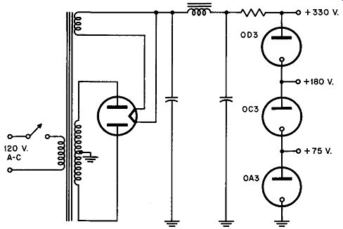
Fig. 14. Practical power supply providing three regulated voltages.
20. Electronic Voltage Regulation
The design of many types of electronic equipment calls for power supplies in which the voltage output must be very precisely regulated. An additional requirement often encountered is that of variable voltage control as well.
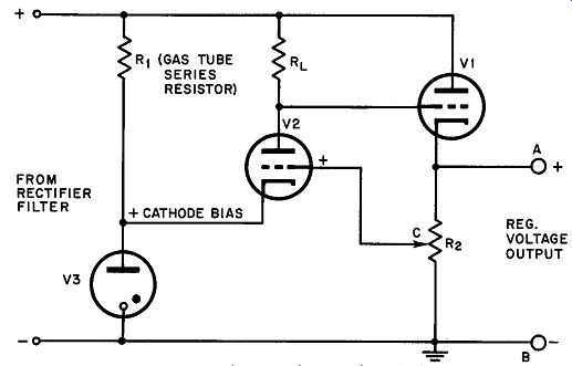
Fig. 15. An electronic voltage regulator circuit.
Figure 15 shows a circuit in which the dc amplifier properties of a triode vacuum tube (used in conjunction with a gas regulator tube as a source of reference voltage) are used to govern the grid voltage of a control tube. The triode (V2) is adjusted to operate as a class-A amplifier while a second triode V1 acts as a variable resistance. V1 is inserted in the circuit in series with the d-c output connection from the power supply proper. The class-A amplifier is connected in such a manner that an adjustable fraction of the output is applied to its grid so that any voltage variations present in the dc output cause the amplifier to change the grid voltage of the series control tube V1. The operation of the system is best understood by following a sequence of voltage variation, feedback, and correction.
Assume that dc voltage output between terminals A and B changes in an upward direction as a result of line variation, load variation, or even residual ripple that has not been removed by the filter network. Point C must then become more positive with respect to ground. The plate current of V2 must increase due to the positive bias. The increased voltage drop across RL reduces the plate voltage of V2 and hence the positive grid voltage of V1 with respect to ground. Since the grid of Vl is now less positive than it was before, its internal resistance increases thereby producing a smaller voltage output across A and B. Note that the phasing is such that the original tendency to change has been counteracted by the voltage-drop variation across V1.
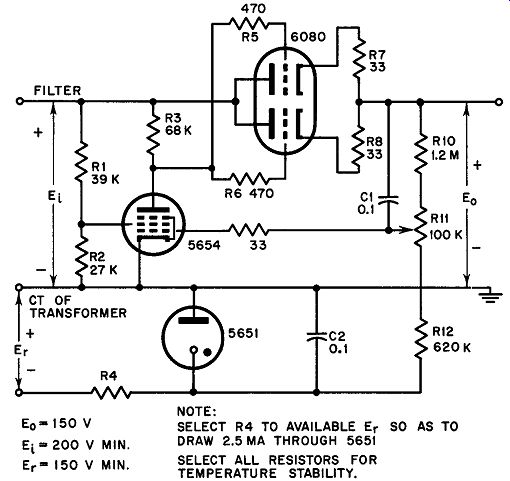
Fig. 16. A practical voltage-regulated power supply.
No mention has yet been made of a very essential part of the arrangement: the voltage regulator tube V3. If V2 is to operate in class-A with a large positive voltage on its grid (from point C), the cathode of the tube must be positive to an even greater extent so that the grid is negative with respect to the cathode. Furthermore, the cathode potential must be held to a constant value - at least within a few percent -- if V2 plate-current changes induced by variations in output voltage are not to change the cathode potential as well. If this were to occur, V2 would shift its operating point with each small change and be far less effective as a control element. For this reason, the voltage drop across V3 is called the reference potential; it is the only potential in the circuit that does not change with line or load variations.
The setting of potentiometer R2 determines the net output d-c voltage of the system. As its wiper is moved farther downward (toward common ground) , the grid of V2 becomes increasingly negative with respect to its "constant" cathode voltage and its plate current diminishes, causing the voltage at the grid of V1 to increase in a positive direction. The consequent reduction in the plate resistance of V1 permits a greater voltage to appear across A and B. Similarly, when the wiper is moved toward higher positive voltages, the voltage drop across RL increases making the grid of V1 more negative. This results in increased series resistance and the output voltage goes down.
A voltage regulating system such as the one just described is also effective in reducing output ripple to about the same extent as it reduces variations in line voltage. Variations in input voltage to the regulator from the rectifier filter are handled in the same manner as a change of line voltage. The values of the components R1, RL, R2, etc. are shown on the basis of the requirements of the particular tubes and voltages used. In practice, a pentode is generally employed as V2 to take advantage of its large transconductance; this necessitates additional small parts for adjusting the screen and plate voltages to the proper relative values. Figure 16 illustrates a practical voltage-regulated power supply using modern vacuum tubes.
QUIZ
1. What is the starting voltage for the 0C3 tube?
2. The maximum allowable voltage range of a 0C3 regulator tube should not be more than __ volts.
3. What is the maximum current range of the 0C3 voltage regulator tube?
4. Check a tube manual to determine typical allowable current ranges for a number of octal voltage regulator tubes; for miniature tubes; for the 5651.
5. What is the maximum recommended current through a VR 0D3 tube?
6. A power supply delivers 350-400 volts. A load connected to this supply needs 150 volts at 30 ma. A series dropping resistor and a VR 150 are used to supply this circuit. Find:
a) a value usable as a series resistor allowing a maximum of 30 ma through the VR tube;
b) the minimum current through the VR tube.
7. A load needs 225 volts regulated. What tubes would you use and how could you connect them?
8. How does VI act in the circuit of Fig. 15?
9. What is the purpose of the VR tube (V3) in Fig. 15?
10. How can we observe if a VR tube is operative?