AMAZON multi-meters discounts AMAZON oscilloscope discounts
21. Construction of a Triode Thyratron
When a control grid is inserted in a thermionic gas diode, the properties of the resulting triode are completely different from those of a vacuum triode. Gas tubes containing a heated cathode, one or two grids, and a plate are known as thyratrons; many small modern thyratrons are equipped with a shield grid inserted for the purpose of reducing control grid current. These will be discussed later. The construction of a typical triode thyratron is shown in Fig. 17A. The grid is usually a hollow cylinder that envelopes both the anode and the cathode with a baffle containing small holes placed between the two elements. The baffle almost completely shields the anode from the cathode so that a small grid voltage may completely neutralize the large potential, thus preventing the initiation of the arc at voltages where it would normally begin.
22. Fundamental Action of a Thyratron in a Dc Circuit
How a thyratron differs from a vacuum triode is easily demonstrated by considering Fig. 17. If T were a vacuum triode, moving the wiper from the minus side toward the plus side of the bias supply would cause a relatively smooth increase in plate current as indicated by the reading of the milliammeter in the plate current.
Likewise, the opposite movement of the wiper would have the opposite effect -- a smooth plate current decrement.
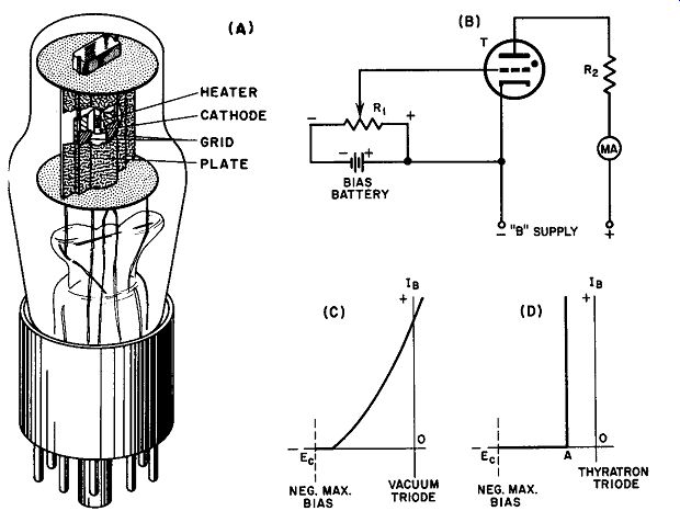
Fig. 17. 884 triode thyratron: (A) cutaway view (RCA); (b) circuit to illustrate
thyratron action; (C) plate current-grid voltage curve of a vacuum triode;
(D) plate current grid voltage curve of a thyratron.
When the vacuum tube is replaced by a thyratron, the following sequence is obtained:
(a) With the wiper fully minus, the plate milliammeter reads zero.
(b) As it is advanced toward the positive side of the battery, the plate current does not rise until the grid voltage has reached a certain critical value.
(c) When the critical value of grid voltage is attained, the plate current suddenly rises upward to its maximum value under the conditions imposed by the voltage of the B supply and the value of R2.
(d) Further movement of the wiper of R1 has absolutely no effect upon the plate current as read by the milliammeter.
(e) As the setting of R1 is changed back toward the minus side, the plate current continues to flow at its maximum value even though the wiper is moved to the full negative position. The voltage on the grid no longer influences the reading of the milliammeter.
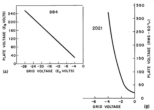
Fig. 18. (A) Critical grid curve for RCA 884 thyratron triode (argon-filled);
(B) Critical grid voltage vs anode voltage curve for average 2D21 with 2-megohm
grid resistor.
It is important to note at this time that a thyratron must never be operated without a plate load. Although this is permissible in a vacuum tube circuit - one, for instance, in which the static characteristics of the tube are being measured -- the absence of a plate load is almost certain to damage the thyratron irreparably if it is allowed to undergo the sequence described above. At the instant when the discharge in the thyratron is initiated (point A in Fig. 17D) , the resistance of the tube drops to a very low figure. Without a series limiting resistor, plate current is excessive and the resulting heavy ionization will cause damaging cathode sputtering.
Once the arc has been started, the grid completely loses control over plate current. After arc initiation, the grid is immersed in a plasma and is separated from it by a positive ion sheath so that varying the grid potential merely serves to change the thickness of the sheath rather than the field gradient. The simplest way to extinguish the arc at this point is to remove the anode potential or reduce it to a figure below the value needed to maintain the arc. When a thyratron suddenly begins to conduct it is said to fire. The term extinguish refers to the transition from the fired state to the state in which complete deionization occurs.
23. The Critical Grid Curve
The bias voltage at which a given thyratron fires differs for different anode potentials. From a qualitative point of view,* it is apparent that a higher plate voltage tends to make the tube fire even though the grid may be appreciably negative. As the anode potential is lowered, firing may be prevented by smaller and smaller negative grid voltages. The value of the series limiting resistor (R2 in Fig. 17B) has no effect on the firing potential since, before the arc begins, there is no current flowing in the resistor and hence no voltage drop. Thus, the anode potential before firing is equal to the source voltage.
Complete firing characteristics of any thyratron may be established in the form of a curve called the critical grid curve (Fig. 18A). This particular tube is argon-filled and contains a constant number of gas molecules; its critical characteristic curve is very close to a straight line over its rated range. For example, to determine the anode firing potential required for a grid voltage of -20 volts, merely find the intersection between the -20 ordinate line and the curve and read the required plate voltage as 142 volts. The graph is used in a similar manner to ascertain the grid potential needed to prevent the thyratron from firing at a given anode voltage.
Often, more curvature is encountered than is reflected in the graph of Fig. 18A. The curves of the 2D21 (Fig. 18B) show a more typical picture. The critical grid voltage curve is a function of the series grid resistor.
Mercury-vapor thyratrons which are quite prevalent in high current industrial applications display a family of critical grid characteristics since the condensed mercury temperature now enters as a third parameter. A typical set of curves for a mercury vapor thyratron are given in Fig. 19. The curves clearly indicate that lower condensed mercury temperatures require less negative grid voltage to prevent firing. As the mercury temperature rises, the gas pressure increases; this sets up a situation in which the tube finds it easier to fire with given grid voltages, hence larger and larger grid voltages are necessary to prevent initiation of the arc.
[some thyratrons require a positive grid voltage to fire.]
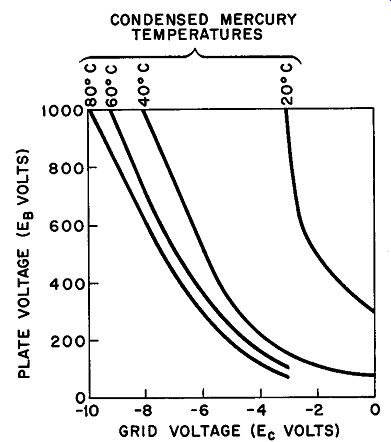
Fig. 19. Control characteristics (critical grid curves) mercury-vapor thyratron
FG 27 A.
24. Quantity Grid Control of Thyratron Trigger
The excellent conductivity of an ignited thyratron immediately suggests the use of this tube as a switch in a d-c circuit. In proper operation, the grid current is very small, a condition that requires very little switching power. In this manner, a very light switch may be used to apply or remove power from devices of much greater power dissipation without switch arcing or pitting. To distinguish this action from others which follow, the term quantity grid control is usually employed to describe this form of switching or trigger action.
To start, let us consider the circuit of Fig. 20 in which a small switch is used to apply power to a heavier load. With switch SW closed, the grid of the thyratron is made substantially more negative than its critical potential at the particular anode voltage being applied. When SW is opened, the grid immediately returns to ground potential (same potential as the cathode) so that the negative bias is zero. The thyratron fires, thus powering the load; it should be noted, however, that closing SW at this time will not turn off the power to the load for reasons given in Section 22. Removal of power can be accomplished in this fundamental arrangement only by removing the anode potential. (We will show later how another small switch may be connected for power shut-off as well as power application. The anode voltage switch in this circuit would have to be sufficiently large to handle the shut-off arc.)
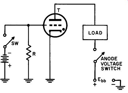
Fig. 20. Trigger action of a thyratron.
Observe that the thyratron in the circuit of Fig. 20 is acting as a latching relay. Even momentary depression of a spring return switch at SW results in continued power to the load. It possesses certain important intrinsic advantages over an electromagnetic relay: a thyratron does not have moving contacts which might corrode and pit; ordinary relays require a relatively long impulse applied to their coils for reliable operation -- not much less than 1/100 second even for good relays. The thyratron, on the other hand, has an ionization time of a few microseconds at the most so that a momentary closure over even this tiny interval will suffice to trigger the circuit.
Of the various gases that have found application in thyratrons, three types are now in favor for the reasons given below:
Mercury-vapor: Low internal voltage drop, capable of carrying heavy currents.
Disadvantage: sensitive to temperature and therefore more difficult to control.
Argon: Higher internal drop than mercury but not sensitive to ambient temperature. Argon tubes are used in light-load circuits where repeatability is important.
Hydrogen: Very fast de-ionization time, hence excellent in applications where extremely short pulses are available for triggering.
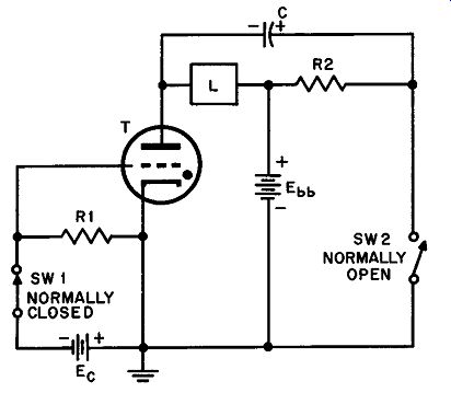
Fig. 21. Thyratron cut-off circuit using a commutating capacitor.
25. Thyratron Cut-off with Capacitor
It was stated in Section 24 that the extinguishing of a fired thyratron operating on dc may be accomplished by means other than the use of a large heavy-current switch. Of the many ways to do this, the use of a commutating capacitor as shown in Fig. 21 is per haps the simplest and easiest to apply. Both switches are spring loaded, SW1 being normally closed and SW2 normally open. To trigger the thyratron on, SW1 is momentarily opened. This grounds the grid through RI permitting the tube to fire since, with the grid at ground potential it is more positive than its critical value. Plate current flows through the load and energizes it, but at the same time the commutating capacitor C charges with the polarity shown in Fig. 21. The reason for this charge is easy to see: while T is con ducting it behaves as though it were a very low resistance so that the left plate of C takes on a potential very close to that of the negative side of Ebb" The right hand plate of C is connected to the positive side of Ebb through R2 and, since no steady current flows through R2, there is no voltage drop in this resistor; hence the right plate assumes the same potential as the plus side of the source Ebb.
There fore the total voltage across C is Ebb minus the voltage drop in the tube - about 15 volts. When SW2 is closed, the voltage on C is instantaneously applied to the anode and cathode of T; since this voltage is the inverse of the normal supply voltage, it subtracts from the latter causing the anode-to-cathode voltage to drop to about 15 volts.
This is well below the voltage required to maintain the arc; hence the thyratron extinguishes in some tubes. When SW2 is released, T does not fire again because SW1 is normally closed and Ee is connected to the grid and cathode in the correct polarity to keep the grid below its critical voltage.
In some circumstances the plate would have to be driven below 15 volts to extinguish the tube, since normal tube-drop may well be less than this. This circuit usually makes the anode negative with respect to the cathode to insure recovery of grid control. The plate to-cathode voltage which exists at the instant SW2 is pressed, depends on the value of the capacitor C and on the load L.
26. A Thyratron in an Ac Circuit
Theater lighting, electroplating, and welding are a few examples of industrial processes in which a controlled amount of rectifier current is necessary. Such control may be accomplished by a variable power transformer or a rheostat in the d-c output of the rectifier; but neither of these methods is particularly satisfactory. Variable trans formers are expensive and output rheostats are highly inefficient.
The development of large thyratrons at relatively low cost has made current control inexpensive and efficient. Before attempting to develop a-c control circuits, it is essential to understand the anode and grid potential relationships in a-c circuits.
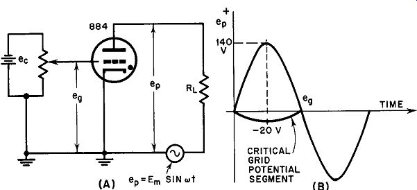
Fig. 22. An a-c thyratron circuit.
Although the critical grid curve for, say, an 884 thyratron is sufficient to predict the tube's behavior in any type of circuit, a more lucid analysis of a-c action is made possible by transferring the coordinates of the curve of Fig. 18A to a plot of sinusoidal nature.
Consider a circuit such as that of Fig. 22 in which a dc source is available to change the negative bias on the thyratron grid and in which the anode potential is sinusoidal ac.
Since the curve of Fig. 18A gives the minimum grid potential needed for conduction to occur for each value of plate voltage, the grid potential which just permits conduction at each point in the cycle of sinusoidal plate voltage may be found point by point from Fig. 18A for an 884 thyratron. In Fig. 22B, the solid sine-wave segment above the horizontal axis represents the anode potential which might make the thyratron fire if the grid voltage is below critical value; the dashed segment is negative anode potential which cannot fire the thyratron under any conditions and so needs no consideration at all. The solid curve beneath the time axis shows how the critical grid voltage must change with anode potential to just prevent the tube from firing throughout the positive half of the anode potential cycle. For example, suppose that eP reaches 140 volts maximum. Then, for peak anode voltage, eg would have to be -20 volts to just prevent ignition of the thyratron. Evidently, each specific anode potential must have associated with it some value of negative grid potential to establish this condition. The critical grid potential segment in Fig. 22B is a plot of these points throughout the positive half of the anode potential cycle.
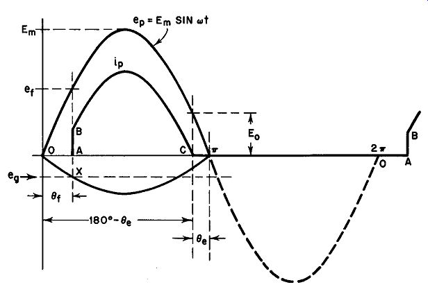
Fig. 23. Relations between plate voltage, plate current, and grid voltage
in a typical thyratron.
Referring to Fig. 23, we can analyze the magnitude and wave form of the current that flows through the load (ip) as a first step in the comprehension of thyratron behavior in a-c circuits. Let us assume that a certain fixed negative bias potential eg is applied to the grid. This bias line intersects the critical grid voltage segment at point X in Fig. 23. This means that conduction will begin when the applied potential reaches the value er - that is, the point directly above the intersection X. Thus during the period O to A the tube is extinguished. At A the thyratron fires and its current iP (ignoring the microsecond or less required for ionization) instantly rises to point B. During the remainder of the conduction period, iP follows Ohm's Law according to the equation:
Em sin rot - E0 lp = RL (17)
… where E0 is the voltage drop across the conducting thyratron (from 10 to 15 volts), Em is the peak value of the sinusoidal applied voltage, and RL is the resistance of the load. This accounts for the shape of iP. At the instant when eP reaches a value equal to the tube drop E0 , iP must equal zero. Calling the angle at which ignition occurs 0r, and the angle at which extinction takes place 0e, we can state the following relationships: (18)
In this case, eP is the applied voltage. Before firing, however, the anode potential of the tube is the same as the applied voltage in the absence of plate current. Hence, eP = ebb before firing.
The voltage at which firing begins, er, is: et = Em sin 0r
Solving Equation 20 for the firing angle 0r we have:
0r = arc sin er/Em (19)
(20) (21)
The thyratron extinguishes when the applied a-c anode voltage drops below E0. Hence the extinction angle is related to the voltages in this way: Solving for 0.
0. = 180° - arc sin E0 /Em
Also, the total angle of conduction may be expressed as:
0c = 0e - 0t (22)
(23)
(24)
These equations have intrinsic value in that they relate firing and extinction voltages to the corresponding angles of the positive half of the applied voltage cycle. A further advantage of collating these equations is that it is now possible to obtain a statement for the average load current supplied by a thyratron during the entire ac cycle. The derivation of the final equation requires a knowledge of integral calculus and will not be undertaken here. It may be stated, however, in this manner: (25)
This simplified form of the final equation is obtained by assuming
•Derivation of lav 2n: 1 .. = 2
~ J ip d (wt) - general form.
0 for firing interval from 0, to 0., we integrate over these limits, also substituting for i• as in Equation l 7.
d(wt)
Evaluating the integral yields:
Em [ 1 •• = 2itRL cos 0, + ? I - ( :: r - :: (0. - 0,) J
If E0 is substantially smaller than Em - the usual case - then this equation may be simplified to: Em 1 •• = 2itRL (I + cos 0,)
(since with this assumption, the second term reduces to unity and the third term drops out entirely) . that E0 is small compared to Em. In most applications, this is perfectly true since E0 is in the vicinity of 15 volts while Em for industrial thyratrons often runs over 800 volts.
Equation 25 shows that the average d-c value of the load current may be smoothly controlled by changing the grid bias, since bias variations cause the firing angle to shift along the time axis. Control of output current in thyratrons by means of bias magnitude changes is sometimes referred to as quantity grid control; more often, the process described here is called gradual control. The limits of variation of the firing angle, with d-c grid control, are from zero to 90°, with maximum d-c current flowing at 0r = 0°. 27.
Phase Shift Control of a Thyratron
A serious deficiency of simple bias or quantity control of thyratrons as described in Section 26 is that the firing angle can be varied only over the limited range from 0° to 90°. A thyratron under quantity control in a d-c circuit acts as a self-latching relay because once the discharge has been initiated the grid loses control and the tube continues to conduct as long as the anode voltage re mains above the arc-maintaining potential (about 15 volts). As we have seen, however, the current passing through the thyratron and its load in an a-c circuit is made variable by varying the grid voltage; also, the grid regains control of the tube on every alternate half cycle of the applied anode voltage when the latter dips below the horizontal axis.
It is apparent on examination that quantity grid control can never provide complete control of the anode current from the full off to the full-on condition because of the 0° to 90° limitation. To clarify this point consider the two extreme conditions: (1) If the firing angle 0r is made 0°, the tube will conduct for almost a full half-cycle. This is the full-on condition. (2) If the firing angle is advanced to very close to 90°, the thyratron will ignite at the peak of the ac anode potential but will remain ignited for the rest of the quarter cycle. This is not the full-off state. Thus, if the plate load were an incandescent lamp, then running the bias increasingly negative would gradually dim the lamp; but long before it reached an "almost out" condition it would extinguish completely. In an industrial application such as house-light control in theaters, this situation would be intolerable.
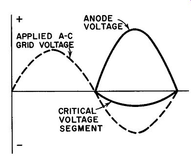
Fig. 24. An alternating voltage of large magnitude applied .to the grid 180°
out of phase with the anode voltage.
Complete control over thyratron load current may be realized by applying phase-shift grid control to vary the firing angle from 0° to 180°. To obtain phase control, an ac voltage of the same frequency as the anode supply voltage is fed to the grid of the tube.
The phasing of the grid voltage is made variable by suitable circuitry to be described shortly. To start, let us apply an alternating grid voltage which is 180° out of phase with the anode voltage and is considerably more negative at its peak than necessary to keep the thyratron cut-off during the entire half-cycle.
Figure 24 shows quite clearly that the thyratron cannot fire at any time under these circumstances because the applied grid voltage is always more negative than the critical grid potential. During the next half-cycle the grid will, of course, go positive but at the same time the anode potential will be negative so that constant extinction is obtained throughout the full 360°. The relative phasing of grid and anode voltages in Fig. 24 may be referred to either as a 180° lead or a 180° lag.
If the phase of the grid voltage is now shifted to a new position such as that shown in Fig. 25, it would be logical to say that the grid voltage is now retarded with respect to the anode voltage by some angle less than 180°. Now, the applied grid voltage intersects the critical voltage segment at point X and a line drawn parallel to the vertical axis intersects the anode voltage curve at point F (line AB) . Hence, the thyratron fires now at point F and remains conducting for virtually all the rest of the half-cycle. Evidently, advancing the phase of the grid voltage further and further along the anode voltage half-cycle will permit the tube to fire earlier in each case. When the grid voltage arrives at the in-phase condition with the anode voltage, the thyratron will fire just as the anode voltage rises above ionization potential at the beginning of the cycle and will continue to conduct throughout the half-cycle. This is the full-on condition. Thus, phase-shift control permits a full range of plate current with smooth variations from the full-off to the full-on state. All that remains is to design a circuit that will provide a phase shift from 180° out of phase to the zero phase condition for the grid voltage with respect to the anode potential.
28. Phase-Shifting Circuits
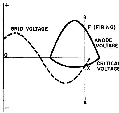
Fig. 25. The alternating grid voltage is now lagging the anode potential by
some angle less than 180°.
Phase-shifting of one voltage with reference to another is easily accomplished by circuits that combine resistive-inductive or resistive capacitive components in phase -shifting networks. One of the simplest arrangements to set up and adjust is the R-C network shown in Fig. 26. A low-voltage center-tapped transformer supplies the a-c bias voltage for the thyratron with a variable resistor R and a capacitor C connected across the whole secondary winding. Grid voltage is taken from the junction between R and C and is referred to G, the point to which the cathode is connected.
Taking point Y as the zero-reference, the current which flows through the R-C combination due to the applied voltage YX must lead Eyx by an angle <I> which depends upon the ratio of capacitive reactance Xe to resistance R. The vector diagram in Fig. 26 shows that I is leading Exy by the angle <I>. The voltage drop in the resistance must be in phase with this current so that vector JX is drawn
26. An R-C phase-shifting network.
parallel to I; on the other hand, the voltage drop in the capacitor must lag behind the current by 90°, thus vector JY is shown at right angles to I and IR. Since vectors JY and JX must total to vector YX, these voltages form a closed triangle in which vector JG represents the magnitude and phase of the varying potential applied between the grid and cathode of the thyratron. Vector JG thus lags behind vector GX - the condition necessary to realize a varying grid potential whose phase may be shifted for purposes of grid control.
Examine the vector diagram in Fig. 26: If R is made zero, vector JX becomes zero, and the grid voltage JG falls into phase with the applied anode voltage. This permits the thyratron to fire at the beginning of each cycle, thus permitting the maximum average anode current to flow. As the resistance is increased, vector JX grows, causing the angle between the grid voltage and anode voltage to increase. As the grid voltage is retarded to an increasing extent, the tube fires later and later in the cycle bringing about a greater diminution of anode current. Phase-shift grid control thereby makes extremely smooth variation of average anode current possible by means of a relatively low-wattage control element, R.
29. Thyratron Grid Resistor and Pre-conduction Current
In the discussion concerning the fundamental behavior of a thyratron, it was pointed out that the tube fired when the grid potential was reduced below a certain critical point. After ignition, the anode current of a thyratron cannot be interrupted by making the grid negative once again since the latter electrode loses control once ionization has begun.
To understand (I) the physical conditions existing after a thyratron is fired and (2) why the tube is endangered unless certain precautions are taken, examine the voltage conditions in the tube structure.
Although a potential of several hundred volts may exist between anode and cathode before ignition occurs, once the gas has ionized the voltage drops to a smaller figure such as 15 volts. The grid of the tube at this time is then immersed in a field having a potential gradient whose magnitude is determined by the voltage between anode and cathode, i.e. about 15 volts. The grid will therefore tend to assume some potential in the vicinity of 15 volts and any attempt to change this voltage - as, for example, varying the d-c bias - will result in large grid currents. To avoid damaging the element, a resistor is always connected in series with the grid potential. If its value is between 15,000 and 100,000 ohms, such a resistor will allow the grid to establish its own potential with a very small grid current. Since some voltage can occur across this resistor due to pre-conduction current, the size of this resistor will influence the critical grid voltage curve.
Another factor is important in thyratron application: pre-conduction grid current. The value of a thyratron as a self-latching relay for example, lies in the tiny grid power requirements for control of the tube before conduction begins. The control surface is very much larger than the equivalent element in a vacuum tube; furthermore, the thyratron grid is immersed in the plasma during conduction and inevitably collects an appreciable quantity of cathode material. Measurement shows that a normal thyratron in good condition exhibits a ·much larger grid current before conduction than the equivalent vacuum tube. This means, of course, that the source of control voltage for the grid must be capable of supplying power rather than merely voltage. This disadvantage is almost completely overcome in shield-grid thyratron design.
30. Shield-grid Thyratrons
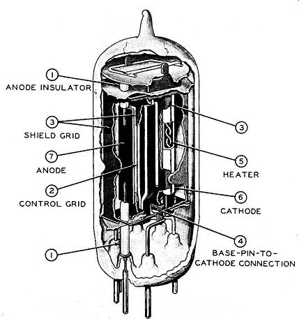
Fig. 27. Internal fabrication af a typical shield grid thyratron (2D21), RCA
Figure 27 shows an internal view of a typical shield-grid thyratron. In this tube, structural precautions have been taken to isolate the control grid from the electron-ion stream that flows between the anode and cathode. The shield grid is a cylindrical structure which completely surrounds the cathode and control grid and is provided
with two baffle plates which confine the arc stream to a path which is well inside the metallic structure of the control grid. By isolating the control grid in this manner, both pre-conduction grid current and the likelihood of damaging post-conduction grid current are minimized. Protective series resistors are not normally needed in the grid circuit of a shield-grid thyratron. Series grid resistors in both control and shield-grid circuits improve tube life in some thyratron applications.
Small shield-grid thyratrons like the 2050 are generally used with their shield grids connected to their cathodes, thus placing the shield grid at zero potential. In this connection with 150 volts between anode and cathode, the 2050 will fire when the grid potential reaches the vicinity of -2 volts. Figure 28 shows a 2050 connected as a non-latching switch that requires infinitesimal grid power.
The circuit owes its non-latching property to the use of ac for anode power. To convert it into a latching relay, de may be used for the anode circuit in place of the ac.
The shield grid can serve as a control grid. Some applications utilize the fact that circuits can be designed so that the shield-grid thyratron will conduct only when both grids are above a critical voltage value.
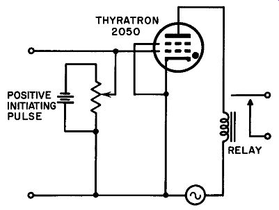
Fig. 28. The 2050 connected os o non-latching switch.
31. Two Direct Applications of Industrial Thyratrons
A thyratron is essentially a grid-controlled rectifier which can replace a vacuum-tube rectifier in any circuit in which control of output voltage is desired. It is natural, therefore, that one would think of this as its primary application. As a matter of fact most thyratrons are not used as rectifiers at all since most industrial applications require a device that will control a-c output without rectifying it. Control of resistance welding machines and large a-c motors are examples. On the other hand, current control and rectification are often necessary characteristics. Hence, thyratron circuits fall into two broad classifications: controlled ac and controlled dc.
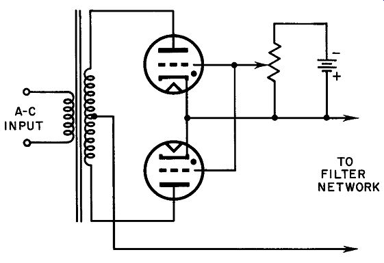
Fig. 29. A full-wave thyratron power supply.
Figure 29 illustrates a full-wave thyratron power supply designed for the production of pulsating de into a filter. Output current is made variable by quantity control in this case, but phase-shift methods may easily be substituted by using circuits described earlier in this Section.
For the operation of transformers or ac motors under controlled current requirements, a pair of thyratrons may be connected back to-back as shown in Fig. 30. In this circuit, each thyratron conducts for one half of the ac input cycle, providing a full sinusoid at the output of the system. Two separate control voltages are necessitated by this configuration as indicated in the schematic diagram, because there is no common point for the return of the positive side of the grid voltage source. When the tubes are cut-off they act like open switches and the full line voltage appears between the two cathodes.
With modern thyratrons, it would be impossible to supply both heaters from a common filament transformer since the cathode-to heater insulation is not effective enough to prevent possible arcing from one electrode to the other. The limitation on heater-cathode voltage in thyratrons is due to the fact that a few microamperes of leakage current can produce ionization that leads to breakdown between heater and cathode. This effect is generally negligible in vacuum tubes. This necessitates two entirely separate heater voltage sources, each insulated for the full line voltage between each other and between the windings and frames. Many industrial devices make use of this arrangement with phase-shift grid control providing smooth, continuous output current from zero to the maximum rating of the system.
32. Thyratrons in High Current Circuits
The structure of a thyratron, like that of a vacuum tube, makes it more suitable for high-voltage low-current circuits than for low voltage high-current applications. Even large industrial thyratrons can handle little more than 10 to 15 amperes continuously. Suppose, for example, that a pair of large thyratrons are to be used as theater dimmers in an arrangement where 50 500-watt lamps are involved.
Taking the current for each lamp at approximately 5 amperes (on a Fig. 30. Method of connecting two thyratrons back-to-back for the operation of a-c loads, nominal 115-volt circuit), this means that the lamps must be provided with a total current of about 250 amperes at 115 volts.
This current is far above the rating of the thyratrons; at the same time, the tubes are capable of handling much higher voltages than 115 volts. This immediately suggests the use of a pair of trans formers, one for raising the applied voltage and the other for drop ping it back to its initial value. A circuit that might be used is shown in Fig. 31. At 100% efficiency, the power in the primary windings of both transformers must be exactly equal to the secondary-winding powers. In actual operation, where 90%effiicient trans-formers are employed, the primary power would be 10% greater than the secondary power in T1. The same would be true of T2.
Hence, the current in the thyratrons would be somewhat greater than that indicated in the figure but would still be substantially below their current ratings.
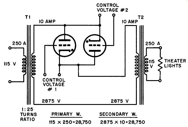
Fig. 31. A method of using high-voltage, low-current thyratrons for controlling
a low voltage, high-current load.
33. Additional Thyratron Circuits
Countless circuits in which thyratrons play an important role may be found in engineering reviews and industrial handbooks.
Two arrangements in which the thyratron is used neither as a control element nor as a trigger are described below: these circuits are interesting because the tubes are handled in a different manner and because the circuits are widely used in modern electronics.
Time Delay Circuit (Fig. 32). When the double pole switch is in position 1, the anode circuit is open (section A) and the grid voltage is appreciably more negative than the critical value (i.e. the critical value for this tube when the given anode voltage is applied later). Capacitor C is charged negatively on the side since it is connected across points C and D on the bias potentiometer R1. There is no current in the load R4 under these conditions.
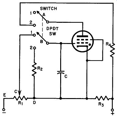
Fig. 32. A practical time delay circuit.
When the switch is moved to position 2, anode voltage is immediately applied but anode current remains zero as a result of the over-critical voltage applied to the grid-cathode circuit by the charge on C. This charge gradually drops toward zero as C discharges through section 2 of the switch and resistor R2. The tube fires when the grid potential approaches the cathode voltage; that is, ignition occurs as soon as the grid voltage reaches critical potential.
The time-delay interval between operation of the switch and the triggering of the thyratron is determined by the original charging voltage as selected by R1 and the R-C time constant of R2C. The timing interval may be increased, for example, by moving R1 toward point E, or by increasing the resistance of R2 and/or the capacitance of C.
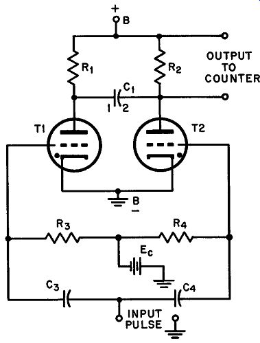
Fig. 33. A binary counter circuit based on thyratron action.
Binary Counter Circuit (Fig. 33 ). A binary counter is a type of 2:1 frequency divider in which every alternate input pulse is mechanically counted. In many industrial and scientific operations, the recurrence rate of the output pulses is too high to be measured by electro-mechanical digital counters. Mechanical counters of the digital variety seldom are reliable at pulse rates higher than about 10/sec whereas substantially higher frequencies are common in sorting, counting and allied control operations in manufacturing plants.
A pair of thyratrons can easily be set up as 2:1 dividers; these may be followed by a second and third pair, if desired, to achieve a geo metric frequency division of 4:1, 8:1, and so on.
The two tubes are biased beyond conduction by the negative voltage from E0 applied to their grids. T2 may now be made to fire by momentarily short-circuiting its grid to its cathode. Assume now that a positive pulse having a very fast rise-time (steep leading edge) is fed to the input terminals. The pulse will be transferred to both grids simultaneously through C3 and C4, but since T2 is already conducting, its operation will not be affected. T1, on the other hand, will trigger if the pulse is large enough to overcome the negative bias of Ee, but as it does so, T2 immediately extinguishes. Conductivity has thus been transferred from T2 to T1
Extinction of T2 at the instant of transfer occurs as follows: while T2 is conducting, C1 is charged to within about 15 volts of the supply voltage and is polarized with side 2 negative and side I positive. (While T2 conducts, it behaves like a closed switch with an internal voltage drop of approximately 15 volts. C1 side 2 is connected to the anode of T2 and C1 side I is connected to B+ through R1 . Since T1 is not conducting at this instant there is no voltage drop across R1 and C1 must charge to a value equal to the applied voltage minus the drop in T2). The firing of T1 with the incoming positive pulse is virtually an instantaneous action. When it happens, the anode voltage of T1 drops about 15 volts. A capacitor cannot instantaneously change its charge, so that as side I of C1 also drops to 15 volts the cathode of T2 (T1 too) instantaneously assumes a potential of about 15 volts through the conductivity of Tube 1. But the anode of T2 is heavily negative (as a result of the stored charge on C1) with respect to its cathode under the conditions imposed upon it by this new situation, hence it must extinguish. Within a very short time, C1 charges again, this time with opposite polarity; but if T2 has deionized before this commutation of polarity occurs it will not fire again since its grid continues to be more negative than the critical potential.
Upon the arrival of a second pulse, commutation again takes place. Thus, Tube 2 conducts only on alternate pulses and the counter forming part of its plate load registers every second signal.
QUIZ
1. What is the major difference between a gas diode and a thyratron?
2. Give the reason for the necessity of a plate load in a thyratron circuit.
3. Why does temperature affect the firing point of a mercury-vapor thyratron?
4. Name three gases used in thyratrons.
5. What is the function of the capacitor in Fig. 21?
6. What is the purpose of the shield grid in a thyratron?
7. Name two devices that use thyratrons to control current flow.
8. How do we hook up thyratrons to get full wave operation?
9. What type circuit will give us control over the average current flow, when the thyratron is used in an ac circuit?
10. Name at least two circuits where the thyratron is not used as control element nor as a trigger.