Dynamic Loudspeaker Most Versatile for Hi-Fi
The speaker that is most common in hi-fi systems is the dynamic type. It is simple to install, simple to connect, may have a wide or a narrowly restricted frequency response as desired, may be used as a direct radiator or converted into a horn loaded system of high efficiency, and may be obtained in a variety of sizes to fit any equipment layout or budget. For this reason, the primary loudspeaker for hi-fi is the "general purpose" dynamic speaker.
The general purpose speaker is one that, when used with other high grade electronic equipment, provides reasonably good musical performance over the complete musical spectrum. This means that the same speaker must reproduce the low notes of the bass violin as well as the high treble notes of the piccolo, and these notes must be reproduced with adequate cleanness, clarity, and precision, permitting no un pleasantness to the listener other than to create in him the desire to own an even more elaborate reproducer system.
When one realizes that the single loudspeaker is called upon to reproduce the whole gamut of notes and tones originally produced by some 75 to 100 instruments ranging in size from the diminutive piccolo to the ponderous tuba and the double bass violin, it becomes nothing short of miraculous that such good quality is obtainable from one comparatively small speaker. One must look with respect upon even the single general purpose speaker.
In any loudspeaker the diaphragm is perhaps the most important factor in the actual sound reproduction because it is the prime vibrating element in contact with the air to be set in motion. The magnetic circuit is important in determining how well the diaphragm is vibrated.
Consequently, we find that the intensity of the sound produced and the frequency range of the sound produced will in a large measure be linked to the magnet circuit design and the diaphragm shape, size, and construction.
The General Purpose Loudspeaker Produces Lows and Highs
Good reproduction of low frequencies is made possible by large diaphragm size; reproduction of good high frequencies by small diaphragm size. In the general purpose speaker, these performance characteristics must be combined into one structure, one "cone" size; consequently, somewhere along the line compromises must be made between low frequency and high frequency extension of range. The eight-inch speaker is perhaps the smallest size that will reproduce low frequencies with reasonable efficiency; its high frequency reproduction is in general excellent. The twelve-inch speaker gives better lows but is usually somewhat less effective in the high frequency region. The fifteen-inch speaker provides the best lows of the three, but in its high end is the most limited. Figure 3-1 shows in a general way the frequency over lapping areas of these three popular sizes of loudspeakers.
Where space for housing the speaker is at a minimum, the eight inch size does a reasonably good job; where space is ample the larger speakers give considerably better low frequency performance. It should be realized that, even though the small speaker may actually reproduce the same low tones as the larger ones, it does so with much less efficiency.
A violin may struggle to make a low note sound loud, but its big brother, the cello, produces that same note with ease and with greater loudness. This is not meant to infer that the eight-inch speaker cannot make good sound, even in a small enclosure. Although there are low notes that this speaker may not reproduce very well, they are not entirely absent. They are reproduced, but with less emphasis. Over 90 percent of the musical spectrum may fall easily within the range of the eight inch speaker, and the other 10 percent is only partly reproducible at reasonable volumes. This is the compromise (not a severe one at that) that must be accepted when the smaller speaker systems are used.
The response of any speaker is, of course, greatly dependent upon the enclosure with which it works. Therefore, compensations may be introduced into the speaker-enclosure combination to extend the low end of the smaller systems. These applications are discussed in Part 2.
Dual Cone Features Built into Single Diaphragm for Lows and Highs
Because the general purpose loudspeaker must reproduce both lows and highs, it must be designed so that the diaphragm is stable enough to be moved as a single whole piston, for good low frequencies depend on the amount of active diaphragm area available to push the air into vibration. At the same time the diaphragm must have built into it at its apex "uncoupling" or disconnecting devices, so that smaller segments may be effectively isolated from the main body of the diaphragm for efficient high frequency reproduction. (See Fig. 3-2.)
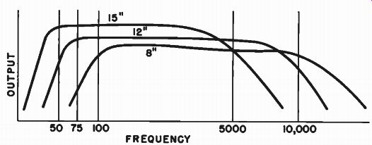
Fig. 3-1. The popular sizes of speakers have overlapping characteristics
of response. The large speakers have more extended lows, the smaller
ones more extended highs.
It may be helpful to point out how a cone may vibrate at low frequencies and at high frequencies at the same time. The un-couplers that make such a dual cone action possible are very much like shock absorbers on an automobile. When you go over a long low swell on the road, the car follows the contour of the road; the action of the shock absorber is at a minimum. If, however, the car meets a section of the road that has many little bumps in it, the car will ride smoothly over it while the shock absorbers quickly take up the small bumps. Thus the wheels of the car vibrate at a high rate while the car body itself vibrates at a slow rate. The shock absorbers are the "uncoupling" devices between the lower and upper sections of the car.
The actual shape of the cone of the loudspeaker itself may pro duce the necessary uncoupling effects; or uncoupling devices may be incorporated in the cone; or the material of the cone may produce the uncoupling effect. The "curvilinear" cone is a popular shape for the general purpose wide range speaker because its slowly curving surface near the apex allows the apex area to "unhinge" itself gradually, as shown in Fig. 3-3. This illustration also shows the built-in type of un-coupler, which is like a small spring built into the cone. (Actually. the uncoupler takes the form of a ridge or corrugation molded into the paper cone.) This spring serves to disconnect the small apex area from the main cone, but does so more abruptly than the curvilinear shape.
--------------------
AT HIGH FREQUENCIES, THE APEX DECOUPLERS ACT AS SPRINGS INSERTED INTO THE CONE ALLOWING THE APEX SECTION TO VIBRATE BY ITSELF INDEPENDENTLY OF THE OVERALL MOTION OF THE WHOLE CONE WHICH VIBRATES ON ITS "MAIN SPRING"
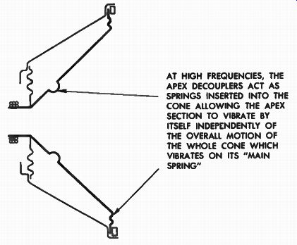
Fig. 3-2. In the general purpose speaker the diaphragm reproduces both
high and low frequencies. In many instances the cone is designed With
apex area "decouplers" to allow more efficient high frequency
response.
"CURVILINEAR" CONE ALLOWS A GRADUAL DE COUPLING OF APEX AREA. THIS CONSTRUCTION SHOWS PLACEMENT OF APEX DOME DECOUPLING SECTIONS BUILT INTO APEX AREA DECOUPLING BY MEANS OF FLEXIBLE RUBBERY BOND BETWEEN SEPARATE APEX AND BODY OF CONE
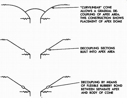
Fig. 3-3. Various means of uncoupling the apex area of a cone for better
high frequency performance.
---------------------
Finally, there is the segmented cone, in which the central area is completely separated from the main cone except for a soft rubbery bond at the place where they meet.
Diaphragm Apex Area Originates High Frequencies
When the proper uncoupling point has been determined it is usually to the advantage of the loudspeaker performance to provide an auxiliary apex dome to the area where the uncoupling takes place.
This apex dome is frequently made of a very rigid but lightweight duraluminum or stiff paper cap. This dome cap serves two purposes.
It closes up the voice coil area, protecting that very vital section from foreign particles. This function is, of course, important for longevity of the loudspeaker. Of more importance, however, is the effect of the dome cap upon the acoustic performance of the loudspeaker. It serves to provide better "polar response" (wide angle response) than the sharp angular section of the cone itself. The apex area of the cone is, in effect, a small megaphone, and like a megaphone will tend to direct its sound into a very sharp directional pattern. In order to minimize this effect, the dome is placed in such a position that it is vibrated by the uncoupled apex area of the cone. Being curved outwardly the radiation it provides is more uniformly circular in pattern than is the conical apex radiation. Thus better wide angle dispersion, in some degree, is obtained by transferring the sound radiation to the more "forward-looking" dome.
High Gap Flux Improves Efficiency and Transient Response
Outside of diaphragm considerations of the general purpose loud speaker, the other important factor affecting performance is the magnetic circuit. The magnetic circuit, which is made up of the magnet itself and the iron around it that completes the path in which the flux exists, should provide as high a gap flux as possible. It should be recalled, however, that gap flux by itself does not determine total performance, because a very heavy diaphragm of improper design can be inferior in performance to a lighter diaphragm of good design integrated with a weaker magnetic gap flux. For fuller treatment of this problem, the reader is referred to Sections 4 and 5. However, as a rule, optimum performance may be expected from good magnetic circuit design.
The heavier the magnet, the higher in the Alnico series the magnet is, and the better the grade of the return iron in the circuit, the higher will be the gap flux. The Alnico V, or "Gold Dot" magnet is in general use today for the better type of speaker. The return iron circuits are usually made of high grade electrical iron such as "Armco", which is steel subjected to special heat treatment in its manufacture so that it may carry heavy values of flux without saturating. High gap flux, which is dependent on magnet type and weight plus good magnetic circuit design results in high conversion efficiency and good transient response. High conversion efficiency simply means getting more out for what is put in. The magnet is the powerhouse; it drives the speaker. The more there is of it, the more it makes itself felt when it interacts with the field set up by the voice coil current.
Transient response of the loudspeaker is the ability of the loud speaker to follow faithfully sharp attacks of notes and to let go of a note once the signal has stopped. The staccato strike of the piano key hammer on the string is a sharp attack; the fading away of the tone is the decay. If the loudspeaker cannot follow the sharp attack of the tone, it will reproduce softer, less staccato tones; and if it doesn't let go of the tone ( if there is "hangover") it will introduce a muddiness into the sound, because it is still playing one note when the next one has already started. (See Fig. 3-4.) A heavy magnetic field provides a strong magnetic impulse to start the speaker moving when the attack comes, and it acts as a strong magnetic "brake" when the signal stops.
Thus the overall magnet conditions of the general purpose speaker determine its tonal fidelity as well as it power efficiency.
---------------------
ORIGINAL SOUND a OUTPUT OF SPEAKER WITH GOOD TRANSIENT RESPONSE
OUTPUT OF SPEAKER WITH POOR TRANSIENT RESPONSE
POOR RESPONSE OF LOUD SPEAKER ON ATTACK NOTES WILL SOFTEN THE ORIGINAL CRISPNESS OF THE STACCATO
POOR DECAY OF RESPONSE FROM LOUDSPEAKER WILL CAUSE "HANGOVER," PER MITTING ONE NOTE TO RUN INTO THE OTHER RESULTING IN MUDDINESS
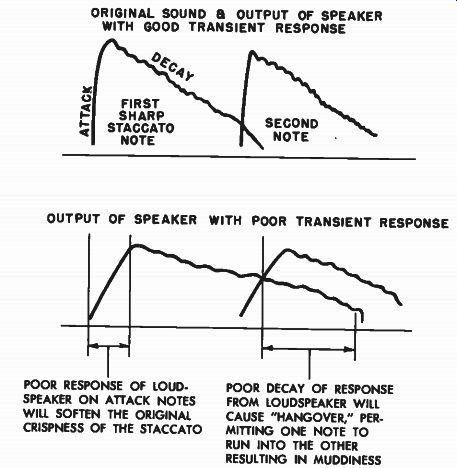
Fig. 3-4. Transient response of a loudspeaker is the ability of a loud
speaker to follow sharp sudden signals, and to let go of the sound as
soon as the signal stops.
--------------------
Addition of Separate High Frequency Diaphragm to Cone Improves Highs
Although the general purpose loudspeaker may be built to pro duce acceptable musical reproduction, it may be varied greatly to provide specialized designs for improved reproduction. One of the first variations that may be made upon the general purpose speaker is to convert it into a "two-way" speaker. Multi-speaker systems will be discussed in detail in section 6, where their advantages and means of compounding the systems will be detailed. For the present we may easily accept the fact that two speakers are usually better than one, and that a single speaker converted to "two-way" action is better than a single one unconverted.
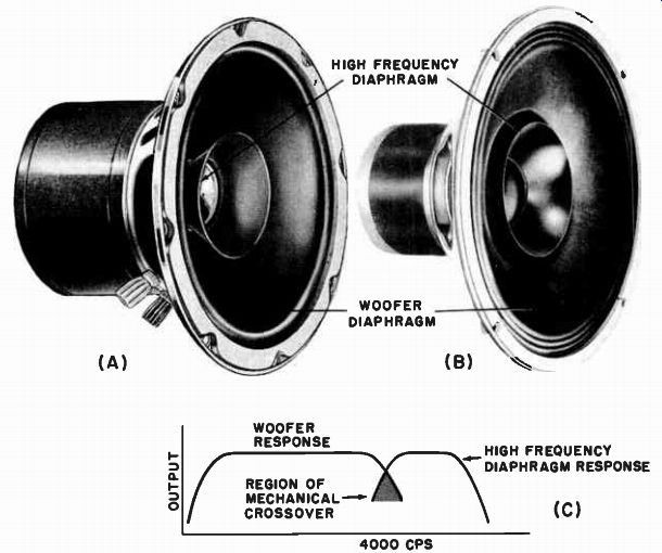
Fig. 3-5. Two-way speakers employing mechanical crossover between woofer
diaphragm and auxiliary high frequency diaphragm. ((A) Courtesy Electro-Voice.
(B) Courtesy Goodmans)
The purpose behind this conversion is to provide more effective high frequency response from the speaker than is possible by the simple decoupling means previously discussed. Through "mechanical crossover" networks it is possible literally to drive two separate diaphragms, a large one for the low frequencies and a small one for the high frequencies, from one voice coil. Speakers of this type are easily recognized by the fact that there is a separate diaphragm affixed to the apex area of the main diaphragm. Two versions of this type of speaker are illustrated in Fig. 3-5. A crossover network (See section 7) is a device, either electrical, acoustical, or mechanical, for slicing a frequency spectrum into separate parts or "bands" for purposes of providing better performance characteristics within the individual bands by separate components than is possible with a single component covering the entire band. In the case of the general purpose speaker previously discussed, the built-in decoupler in the diaphragm actually performed the job of a mechanical crossover; it separated, by means of a mechanical "shock absorber," the high frequency vibrations from the low frequency vibrations, and directed them into separate sections of one diaphragm. In a very general sense, then, even the general purpose speaker is a two-way speaker of sorts.
High Frequency Diaphragm Separated from Main Diaphragm by Mechanical Crossover
But now we are going to approach the problem of mechanical crossover from another angle. Providing two separate diaphragms, rather than making two out of one, is of advantage in that the high frequency diaphragm may be more precisely controlled in dimension, weight, shape, and size, for improved high frequency response than if it were physically integral with the main diaphragm. If the reader were to examine the constructions shown in Fig. 3-5 "in the flesh," he would see that not only are the two diaphragms of one speaker completely different in geometric shape, but the auxiliary high frequency diaphragms are, in addition, made of a paper stock different from the woofer diaphragms.
The woofer diaphragm is made entirely of the paper stock best suited to low frequency performance, and the smaller high frequency diaphragm is made of the paper stock best suited to high frequency reproduction. If the woofer diaphragm is fabricated of soft stock, no special decoupling devices are necessary to isolate the high frequency vibrations of the voice coil from the woofer. Its own softness will prevent the high frequency vibrational energy from getting any appreciable distance up the main cone. The cone material in this case is in its own decoupling agent; it provides the mechanical crossover that admits low frequencies into the woofer but discriminates against highs.
What then prevents the low frequency vibrations from being transmitted to the small diaphragm? Actually, nothing prevents the small diaphragm from being driven mechanically by the low frequency vibrations. But as far as contributing to the production of low frequency sound energy, the small diaphragm plays a very small part. It is too small physically to reproduce low frequency sound adequately.
--------------
EAR "ON AXIS' HEARS ALL FREQUENCIES HIGHS MIDDLES LOWS LOW FREQUENCIES SPREAD OUT EVENLY HIGH FREQUENCIES ARE BEAMED ALONG THE CENTRAL AXIS OF THE SPEAKER. EAR "OFF AXIS" LOSES HIGH FREQUENCIES
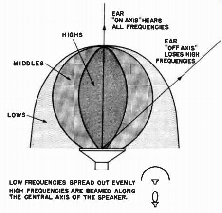
Fig. 3-6. A cone speaker tends to concentrate the high frequencies
on the central axis of the speaker, causing loss of fidelity off the
axis.
----------------
The mechanical crossover thus works in two ways. High frequency vibrations are kept out of the woofer cone by its own decoupling characteristics, and thus it does not radiate them. Low frequencies do tend to get into the high frequency diaphragm, but are not radiated because of the small size of the diaphragm. Thus the mechanical crossover is completed. Figure 3-5(c) gives the typical response of the woofer and tweeter sections of assemblies such as those illustrated.
The overall frequency response of this type of structure is usually considerably better than that obtained from the general purpose cone.
The low frequency response of the two-way mechanical crossover system is improved because the large diaphragm does not have to be compromised in design to handle high frequencies. In addition, the high frequency radiator may be designed for optimum high frequency radiation without being compromised by the woofer diaphragm proper.
Separate High Frequency Apex Diaphragm Aids Dispersion of Highs
The reproduction of high frequencies poses another problem besides that of the level of acoustic output. High frequencies do not spread out as easily as do low frequencies; they tend to beam straight ahead. The higher the frequency, the tighter the beam. This means that if the listener were to be seated to one side of the speaker ("off axis" ), he would hear much less high frequency sound from his loudspeaker than if he were sitting directly in front of it. This effect, illustrated in Fig. 3-6, may be minimized in multi-speaker systems that employ special tweeters ...
WOOFER CONE HIGH FREQUENCY DIAPHRAGM DIFFRACTION RING
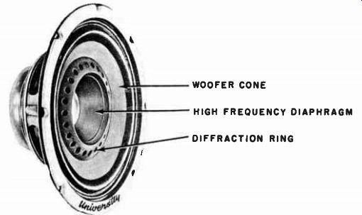
Fig. 3-7. A two-way speaker with mechanical crossover between woofer
diaphragm and high frequency diaphragm, using a diffraction ring to
aid the diffusion of the high frequencies over a wider angle. ( Courtesy
University)
... providing "wide angle coverage." However, in the single speaker structure such as the extended range speakers just discussed, high frequency beaming may occur unless special additional elements are built into the speaker design.
One of the high frequency spreading devices added to an auxiliary high frequency diaphragm with a mechanical crossover system is illustrated in Fig. 3-7. This is the "Diffusicone" construction. The auxiliary diaphragm is driven by the voice coil, with the main diaphragm effectively uncoupled from it for these high frequencies by its shape and material construction. The treble diaphragm now radiates high frequency sound from its forward surface. However, as in all loud speakers, there is also sound coming from the back of the treble diaphragm. Before this rear sound can emerge, it passes through a diffraction ring containing many relatively small holes. When the sound from the back of the auxiliary high frequency diaphragm tries to squeeze through these holes, it "spurts out" in many directions, giving the overall high frequency response a wider angular coverage.
WOOFER CONE METALLIC SPREADER AND REFLECTOR FOR HIGH FREQUENCIES
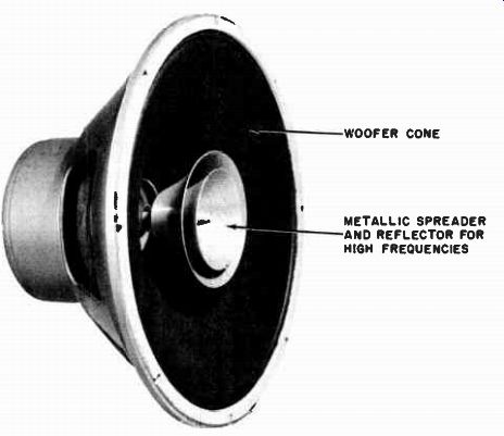
Fig. 3-8. Spreading of the high frequencies from the apex area of this cone
is accomplished by the stationary metal co-spiral structure placed in the
center of the cone, acting as a scattering reflector for the highs. (Courtesy
Stephens)
Another diffusion scheme is the spiral deflector shown in Fig. 3-8. This structure consists of spiral metal deflectors within the apex area of the cone proper. Sound waves that hit this deflector are spread out over a wider angle than if the deflector were not used. Being placed at the apex area, this deflector will be most effective for those frequencies that are generated at the apex, i.e., the high frequencies. It will be observed, however, that there is no auxiliary diaphragm in this structure, hence it falls in the category of the general purpose speaker rather than in the mechanical crossover class.
It is hoped that what has been accomplished so far is an appreciation of the general purpose hi-fi speaker and the extension of its principles into the wider range two-way systems with mechanical cross over features. Accordingly, we are now ready to discuss in detail such components as woofer, mid-range, and tweeter speakers which go into the making of such multi-speaker systems.
Specialized Limited Band Speakers Improve System Performance
Although the wide extended range speaker has certain qualities that make it a fine speaker for simple hi-fi systems, there are definite limitations to its performance. There is a wastefulness of precious high frequency audio power (see section 7) despite the fact that there is definite mechanical crossover. Furthermore, there may be mechanical intermodulation between the two portions of the two-diaphragm speaker. The answer to better utilization of audio power obviously lies in the use of more highly efficient units.
Increased efficiency may be obtained by making the reproducer units more specialized, within limited bands, rather than spreading their power out over a wide band. Thus "woofers" are narrow band speakers that are highly efficient for low frequencies; similarly, "tweeters" are narrow band speakers that are highly efficient for high frequencies.
A combination of a specialized woofer and tweeter thus makes a multi speaker system of higher efficiency than is generally obtainable from a wide range single speaker. In addition, the use of two separate speakers considerably reduces the possibilities of intermodulation distortion (the interaction between two different notes, one high, the other low, both emanating from the same moving structure when it is not completely linear in its motion). Problems such as wide-angle response, presence, brilliance, and balance, may also be more effectively treated by means of multi-speaker systems. Accordingly, we are now ready to discuss the elements of multi-speaker systems -- the woofer, midrange, and tweeter reproducers.
Woofer Designed for Maximum Efficiency at Low Frequencies
Although a woofer is an integral part of a good high fidelity wide range speaker system, it is not in itself a wide range unit. It is, on the contrary, a loudspeaker that is very restricted in range; it is limited to the reproduction of the lower part of the acoustic spectrum -- the bass notes. But, because it is restricted, it may be designed to provide much more efficient and clean bass reproduction than would be possible from a single wide range speaker in which compromises must be made between highs and lows to obtain reasonably good all around reproduction. The fact of the matter is that when a speaker is designed for specialized work, we may give special consideration in the design to those factors which are specific and peculiar to the range in which the speaker is to operate.
Whereas a single wide range speaker must be compromised in size to obtain both good lows and good highs, the woofer is concerned only with the reproduction of the low frequencies. Therefore, it is characterized generally by the same features that characterize musical instruments designed to create the bass notes. The woofer is large in size, rugged in construction and attuned to (or has a resonant frequency falling in) the very low end of the audible range. It is also capable of producing large amounts of sound. All these factors are integrally related to one another in the final design of the speaker. It is possible, however, to dissect then separately to understand the general bearing they have upon the performance of the speaker.
Woofer Diaphragm is Large, Has Low Resonance
Perhaps the cornerstone upon which all the other design parameters are built is that of the natural resonance frequency of the woofer. Woofers have low resonance frequencies; that is, they are "tuned" to resonate and to be most efficient in the low frequencies.
Low resonance frequency is obtain by heavy diaphragms lightly suspended as shown in Fig. 3-9. The heavier the diaphragm, the lower the resonant frequency. The looser the edge compliance that holds it in place, the lower the resonance.
There are specific limits to weight of diaphragm and looseness of suspension that are determined by the mechanical problems involved in good hi-fi speaker design. Even though a diaphragm may have low resonance and be attuned to the low frequencies, it has to have a large vibrating surface for the low notes to be efficiently radiated and adequately projected into the listening area. The bass violin, for instance, has a large vibrating body. The bass drum has a large vibrating membrane. The tuba pushes out a large volume of air. Similarly, the woofer must actuate a large volume of air. Its diaphragm is therefore made as large as possible, consistent with the other factors of the weight of the diaphragm and the actual structural mechanics of its design. The larger the diaphragm, the more efficient the reproduction of the low frequencies. If it were possible to build a speaker as large as a bass violin, it would reproduce the original tones of that instrument with comparative ease. However, such a speaker would pose other problems in design that would make it impractical. We must be content with a reproducer somewhat smaller.
It will be realized, then, that in accepting a vibrating body that is smaller than the original instrument, either a compromise must be ...
LOOSELY SUSPENDED HEAVY DIAPHRAGM FOR WOOFER: INCREASING DIAPHRAGM WEIGHT LOWERS RESONANCE LOOSENING OF SUSPENSION LOWERS RESONANCE INCREASING DIAPHRAM AREA IMPROVES LOWS
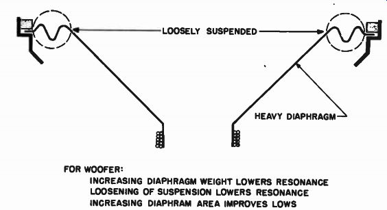
Fig. 3-9. To achieve low natural resonance, woofers have heavy diaphragms loosely
suspended. To achieve efficient low frequency radiation, woofer must be large.
... made in performance or other characteristics must be built into the design of the reproducer to compensate for the necessary reduction in diaphragm size of the woofer as compared to the original instrument.
The acoustic power output of any vibrating instrument is, first, directly proportional to the area of the vibrating surface. The larger the vibrating membrane, the more air is set into motion. Secondly, the power output is proportional to the displacement of the diaphragm in a given short period of time, for the more the diaphragm moves and the faster it moves, the more air will be set in motion. If, then, we cannot have a vibrating body as large as a bass violin as a reproducer, and we have to be satisfied with a smaller vibrating instrument, such as the diaphragm of a 15-inch woofer, we may compensate for the small size of the diaphragm by making it move over larger distances than did the panels of the body of the original bass violin. Thus the woofer diaphragm is characterized by large available vibrational excursion, in addition to as large a physical size as it practical, plus a low resonant frequency obtained from a heavy diaphragm loosely suspended in relation to its mass, so that large amounts of low frequency acoustic power may be generated. Figure 3-10 indicates the general physical characteristics of some typical loudspeakers in terms of these factors.

Fig. 3-10. Physical characteristics of typical loudspeakers of popular
sizes showing relationship of size to resonant frequency, diaphragm
weight, and excursion necessary to generate one acoustic watt.
Woofer Voice Coil Carries Most of Audio Power
Acoustic measurements made on live orchestral performances show that by far the largest amount of sound power produced by a symphony orchestra resides in the lower bass registers. We would naturally expect, therefore, that the woofer would be constructed to handle the largest proportion of the amplifier power representative of the original program source. Accordingly, the voice coil of the woofer is generally large and heavy.
The woofer voice coil must be able to dissipate the heat generated in it by the large proportion of electrical power fed to it; otherwise, the cement binding it to the coil form would soften or over-bake to a crumbling crispness. The form on which the coil is wound may be come overheated, charred, and therefore weak and brittle. All of these effects would rapidly shorten the life of the speaker. However, the larger the coil, the more radiating surface is available for the generated heat to escape and the cooler the coil.
There is another more important reason, acoustically speaking, for the voice coil of a woofer to be large. In order to drive the comparatively heavy diaphragm of the woofer, a considerable driving force on the diaphragm must be developed by the reaction of the voice coil current with the permanent magnet gap field. This reaction is obtained by providing a voice coil with many ampere-turns. This means that we want to get as much current (amperes) as possible through as many turns (of coil) as possible in order to develop a large voice coil magnetic field, which will then interact with the gap field. Thus the more turns we can put on the voice coil the more ampere-turns we can have with a given current. Also, the larger we make the wire size, the more current can be forced through the wire; again we have more ampere-turns. Thus more wire turns of larger size wire means more driving force developed by the voice coil, and it also means a larger coil.
However, there is a practical limit beyond which it does not pay to increase the voice coil mass, because, after all, the voice coil has to move itself as well as the diaphragm. If most of its developed driving force is used up in moving itself, its usefulness has been wasted as far as developing acoustic power is concerned. Therefore, in practice there is an optimum weight of voice coil dictated both by the necessary power handling capacity and the mass of the moving diaphragm.
Dense Gap Flux Needed to Drive Heavy Woofer Moving System
In view of the relatively heavy diaphragm and voice coil of the woofer, it is important that there be sufficient magnet power available to drive adequately this heavy mass. The large low frequency currents flowing through the woofer voice coil will produce only feeble results if the field it produces cannot reach out and react with a dense gap flux.
Dense gap flux means a high degree of reaction between the gap flux and the voice coil field, and large resultant motions will occur. Consequently, woofer magnetic structure are heavy and massive.
The density of the gap flux not only imparts drive to the system, but also serves a very important function as far as cleanness of response is concerned; namely, the damping of the loudspeaker (see section 5). A heavy magnetic field provides a good sturdy propulsive force for the attack of the notes, and also provides a good magnetic brake for the speaker when the signal note has stopped. The heavier the gap flux, the better the electromagnetic propulsive force and damping effects. In woofers where the inertia of a heavy moving system is relatively great, these effects of dense magnetic gap fields in overcoming the inertia of the heavy moving system both in starting and in stopping its motion are of great importance.
In summary then, the general characteristics of woofers . are low resonant frequencies achieved by large heavy diaphragms and loose suspensions, large acoustic outputs achieved by large diaphragm excursions, high power handling capacity through large voice coils necessary to drive the heavy diaphragms, and large magnet structures and gap flux for adequate driving force and damping control.
Tweeter Designed for Maximum Efficiency at High Frequencies
For the high end of the acoustic spectrum there is the tweeter.
Again, because the tweeter is restricted in range, it may be more specialized in design in favor of improved high frequency efficiency, with sacrifices being made in areas where good performance is not expected of the speaker. Since the tweeter is to reproduce the high frequencies, or the treble notes, it must be attuned, or resonated, in the high frequency region. High resonant frequency is obtained with structures that are light in weight and stay supported, as indicated in Fig. 3-11.
Consider, for instance, the very light, tightly stretched E string of the violin, which produces the very high treble notes, compared to the long, loose, heavy G string of the bass violin, which produces the low bass notes. Thus in the tweeter the diaphragm is very light, and relatively stay supported.
Tweeter Diaphragm is Small, Has High Resonance
Naturally, if we wish to make the diaphragm light in weight, it must become small in size. Therefore, in contrast to the large 15-inch woofers, we usually find cone type tweeters in the 3-inch class. By reducing the diaphragm both in size and in weight, it becomes necessary to proportionately reduce the voice coil to get optimum drive of the diaphragm by the coil. As a result of the entire moving structure of the cone type tweeter being so diminutive, it becomes almost a scaled down model of the larger woofer, but with a high resonance frequency.
It is fortunate for the design of the tweeter voice coil that only a comparatively small amount of electrical power resides in the high frequencies. Therefore, the small voice coil found to be mandatory for acoustic reasons will not be subjected to excessive electrical power beyond the capacity of the scaled down voice coil structure. Invariably, the tweeter voice coil is wound with aluminum wire or ribbon because of the lighter mass of such a coil as compared to a copper coil. Inasmuch as lightness of moving system is the prime requisite of tweeters (along with stiffness of suspension), the lightweight aluminum wire affords specific high frequency advantages over copper voice coils.

Fig. 3-11. To achieve high natural resonance, tweeters have small,
light diaphragms, stiffly supported.
Cone Type Tweeters Produce High Frequency Beams
In our discussion of the general purpose of wide range speakers, we touched upon the problem of the beaming effect of high frequencies from cone type speakers, which tend to concentrate those high frequencies along the axis of the speaker. This means that a single cone type tweeter does not produce even distribution of high frequency sounds into the listening area it serves. It "lobes" the higher frequencies out directly in front of it and discriminates against high frequencies at the sides. This condition may be overcome by arranging two or more cone type tweeters in an arced array (Fig. 3-12) so that several individual lobes coming from the separate speakers cover the listening area. This provides some measure of desirable wide-angle response, ...
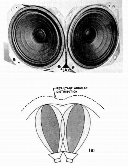
Fig. 3-12. Cone type tweeters may be arranged in an arc array to improve
the angular radiation by providing multiple beams.
... although there are irregularities in distribution because of the spacing of these lobes, as shown.
Horn Loading Permits Diaphragm Size Reduction and Increases Efficiency
In order to get reasonable output from an acoustic radiator, we must vibrate large volumes of air; in order to vibrate large volumes of air, we must usually have large vibrating surfaces. However, this is true only of the direct radiator, the type of loudspeaker that faces the listener directly as it plays. In the direct radiator, the larger the diaphragm surface the greater the output, if the excursion is maintained.
--------------------
THIS SIZE OF DIAPHRAGM WHEN USED AS A DIRECT RADIATOR WILL PRODUCE APPROXIMATELY THE SAME SOUND OUTPUT AS: THIS HORN RADIATOR WHEN DRIVEN WITH APPROXIMATELY ONLY 20% OF THE DIRECT RADIATOR POWER BECAUSE OF THE SMALL LIGHT DIAPHRAGM OF THE COMPRESSION DRIVER
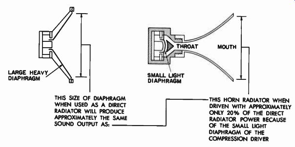
Fig. 3-13. The compression type driver has a small, light diaphragm,
which is easier to drive than a large cone diaphragm. The pulsations
produced by the diaphragm at the narrow throat are transmitted to the
horn mouth, which becomes the radiating surface.
-------------------
However, if the diaphragm must be made small to have a high resonant frequency, only a small volume of air is moved and reduced acoustic output occurs.
However, increased acoustic output from any type of diaphragm may be obtained if it is coupled directly to a horn, converting the system to a horn loaded system. Furthermore, by the addition of a horn, the size and mass of the diaphragm of the driver unit may be reduced even further.
Figure 3-13 shows in general how the size of the diaphragm may be diminished, when driving a horn, in contrast to the size of a direct cone radiator. The driving force of the voice coil of a horn loaded driver is imparted to a small diaphragm and the expanding air column of the horn. The mouth of the horn may actually be considered to be the final vibrating diaphragm. The driving force in such a system may thus be considered to be distributed between the mass of the diaphragm, which has been greatly decreased, and the mass of the air in the horn. However, since air is so much lighter than paper, the overall load of the horn column on the voice coil, for the same acoustic output as a direct radiator cone, may be greatly reduced and the efficiency of the system correspondingly increased. Conversely, of course, for the same electrical input, the horn loaded system will produce more output than the direct radiator type.
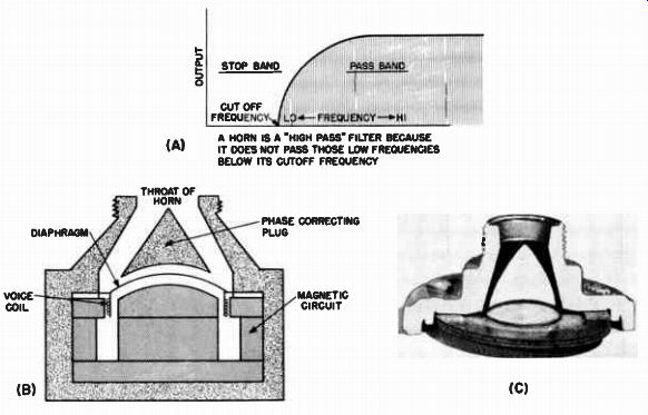
Fig. 3-14. In compression driver, back of diaphragm is sealed off,
creating an acoustic stillness, which helps raise the resonance of the
unit into the pass band of the horn. (C) Shows a cutaway photo of part
of the structure illustrated at (B).
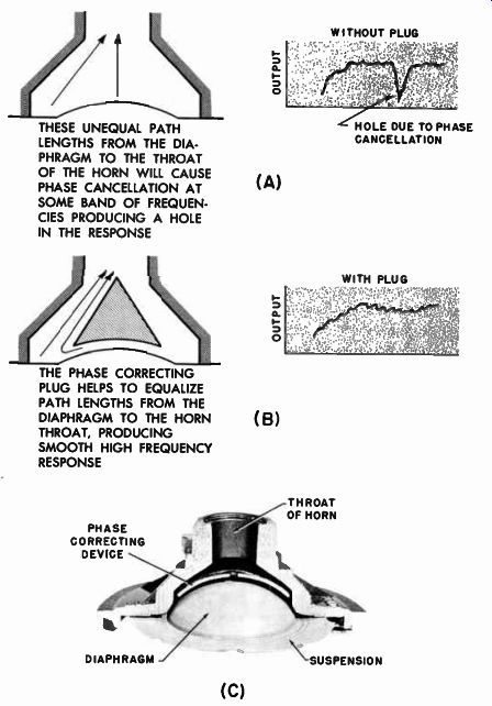
Fig. 3-15. The phasing plug in the acoustic circuit of the compression
type driver unit eliminates holes in the high frequency response due
to path length differences from the diaphragm to the throat. Another
type of phasing device is shown in the cutaway photo at (C).
THESE UNEQUAL PATH LENGTHS FROM THE DIA PHRAGM TO THE THROAT OF THE HORN WILL CAUSE PHASE CANCELLATION AT SOME BAND OF FREQUEN CIES PRODUCING A HOLE IN THE RESPONSE
THE PHASE CORRECTING PLUG HELPS TO EQUALIZE PATH LENGTHS FROM THE DIAPHRAGM TO THE HORN THROAT, PRODUCING SMOOTH HIGH FREQUENCY RESPONSE
As will be shown in Part 2, a horn is essentially a baffle. It provides an acoustic load for the actual mechanical driving system. Horns are "high-pass" filters; i.e., their high frequency range is generally unlimited, but the low frequency range is determined by the acoustic design of the horn. (See Fig. 3-14.) Therefore it is necessary to make sure the driver unit is designed to be most efficient within the range in which the horn is to operate, and not spread out in efficiency over a non-usable range.
Accordingly, we find that driver units for horn systems are of the compression type, with the back of the unit completely sealed to provide acoustic stiffness (a stiff air cushion for the back of the diaphragm). This added stiffness raises the resonance of the unit and makes it more efficient in those high frequency ranges where the horn is most efficient. Thus the combination of the compression driver horn loaded system becomes an extremely efficient high frequency reproducer. Figure 3-15 illustrates the use of the important phase correcting plug that is found in high frequency driver units. This plug serves to equalize the path lengths of the sound "rays" from the diaphragm so that they all meet in-phase at the throat of the horn, giving maximum high frequency efficiency, without frequency cancellation effects.
Tweeter Horn Design Provides Controlled Angular Dispersion of Highs
However, there is more to acoustic reproduction than just efficiency. There is the all-important matter of angular dispersion. The characteristic lobing effect of the cone type tweeter in the high frequency region may be overcome by the use of horns designed for wide angle distribution. In fact, the horns may be designed so that they may actually mold the sound field into various patterns as desired, giving a controlled wide angle distribution. Horns for such application are generally "cobra" shaped. They are not round, but rectangular in mouth configuration. Several of these horns are shown in Figs. 3-16 through 3-20, and it will be observed that they obviously function on different principles. The four general types are the multicellular, diffraction, acoustic lens, and reciprocating flare horns.
The Multicellular Horn
The multicellular horn as shown in Fig. 3-16 is essentially a group of horns all radiating by themselves as separate and distinct little horns, but energized by a common driver unit. The method by which this type of horn distributes the high frequencies depends on the manner in which the individual horns are stacked, and not at all upon the design of the individual horns. As will be observed from the illustration, the multicellular cluster is made up of small square-mouthed horns. Since these individual component horns have symmetrical mouths and symmetrical expansions in both the horizontal and vertical directions, the single horn element itself does not determine the direction in which the sound propagates. That is, the sound from the individual horn spreads out equally into the vertical and horizontal directions.
The elemental horn of the cluster does not by itself produce wide angle dispersion of the high frequencies. However, since these component horns are stacked in any array, which is broader than it is high, as shown in Fig. 3-16, more horns throw sound into the horizontal direction than in the vertical. Thus wide angle dispersion of the sound is effected in the horizontal plane. The effect is materially aided by the fact that the horns are swung around in an angular array.
Since the multicellular horn is made up of individual radiators, it is to be expected that the radiated field pattern of each individual horn will overlap those of its adjacent horns. The result of the inter actions of the individual field patterns is an overall radiation pattern characterized by lobes and valleys not too different from those which occur when cone speakers are ganged into an array. Each little horn mouth sends out a more or less directional lobe similar to that from a cone. Arrays of this type are usually described by the number of horns in one direction as against the number in the opposite direction.
Thus the one shown in the illustration is a "three by two" horn.
There are some types of tweeter horns used in coaxial assemblies that give the appearance of being multicellular but are actually composed of a simple flared horn with fins inserted in the mouth of the horn. These fins sometimes serve to reflect the sound into a wider pattern, but here again, the fins cast acoustic shadows just as easily as they cast acoustic reflections; consequently, the field pattern of the latter type of "pseudo-cellular" horn is also characterized by lobar irregularities.
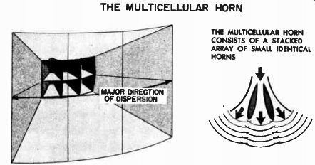
Fig. 3-16. The multicellular horn field pattern is made of separate
sound beams radiated by small individual horns arranged in an arc.
The Diffraction Horn
The diffraction type of horn, illustrated in Fig. 3-17, works on the principle that sound coming out of a narrow slit that is small compared to the wavelength acts somewhat as a "point source," and the sound coming through it will consequently emerge in a cylindrical wave front pattern from the slit, as shown in the illustration. Especially will this be true if there is no baffling on the sides of the narrow slit.
The absence of the baffling allows the cylindrically formed wavefront to flow around the side walls of the narrow mouth of the horn. In more precise terminology, the wavefront diffracts out of the narrow slit around the mouth edges; thus the term "diffraction" horn.
THE DIFFRACTION HORN MAJOR DIRECTION OF DISPERSION HORN EXPANDS UNIFORMLY IN VERTICAL DIRECTION, IS UNFLARED IN HORIZONTAL DIRECTION 1 THIS DIMENSION IS FLARED TO PROVIDE PROPER CUT OFF EXPANSION OF HORN THIS MOUTH DIMENSION SMALL COMPARED TO WAVE LENGTH MAKES MOUTH A "SLIT" SOURCE
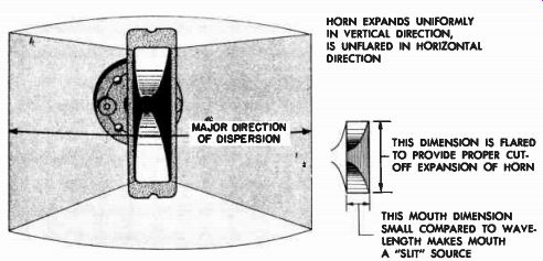
Fig. 3-17. The narrow mouth behaves as a "slit" and wavelengths
that are large compared to the slit emerge as from a point source, diffracting
into a cylindrical wave.
Because the mouth diameter is so small in the horizontal direction (with the horn mounted as shown in the illustration), it must flare out rapidly in the vertical direction to provide the proper overall horn expansion for the cutoff frequency for which the horn is designed.
Thus in appearance it may seem that the greatest horn dispersion will be in the vertical plane because the mouth contour seems to greatly favor this direction. Actually, however, the reverse is true, and for the diffraction horn of this variety, the major energy distribution is in the horizontal plane. However, since the slit effect exists for conditions in which the width of the slit is small compared with the wavelength of the sound, the effective dispersion will be variable with frequency. As the frequency goes up (smaller wavelength) the slit "opens up" and there is comparatively less diffraction. However, despite this reduction of the dispersion of the higher frequencies, in this type of horn there is smooth angular response devoid of lobes or valleys because of the absence of beaming cells.
The Acoustic Lens
The acoustic lens is a means of controlling the directional spread of sound by placing in the sound beam arrays of obstacles arranged in specific geometric pattern. As a point of interest, the acoustic lens was an outgrowth of research on microwave radio transmission. In the course of studying the behavior of electromagnetic lenses for the purpose of focusing and beaming these very high frequency waves, certain difficulties were encountered in constructing suitable laboratory models and equipment with which to carry on the work in an expeditious manner. Since the actual wavelength of the electromagnetic microwaves was very similar to that of ordinary high frequency sound waves, it was found that valuable laboratory time could be saved and the study accelerated if acoustic models of focusing devices were used along with beams of acoustic energy to replace the electromagnetic focusing devices and the electromagnetic wave. From these studies emerged the acoustic lens as a means of aiding the distribution of high audio frequencies over a wide horizontal plane.
One form of the acoustic lens is shown in Fig. 3-18. It consists of stacked layers of perforated screening with discretely enlarged open areas in the center of the disc. The spacing between the screens, the size and separation of the individual small holes in the screen, and the progressively changing large opening in the center of the screens all determine the exact manner in which sound dispersion takes place.
Although the exact analysis of the manner in which this dispersion takes place is founded on optical theory, we may readily understand the function of the lens by examining what happens to a sound wave as it hits an obstacle array. It will be realized of course that a screen with many holes in it is as much an array of obstacles as would be the case if a lot of little discs were placed in the beam. In the case of the perforated screen, the holes are "free space," and the material between the holes constitutes the "obstacle" of the obstacle array.
What then happens when a sound wave hits an array of obstacles in its path? Naturally, where there are openings through the obstacle array, the sound wave will try to squeeze through these openings. Where there are obstacles, the sound wave will not get through, but will be stopped and reflected back in the general direction from which it came.
Thus, we may say that if only part of the sound wave got through the obstacle array, and the other part were stopped within the array, the density of the air in the array would increase, due to part of the sound...
THE ACOUSTIC LENS CURVED WAVE APPARENT INCREASE OF DENSITY OF MEDIUM DUE TO OBSTACLES IN PATH SLOWS UP ENDS OF WAVE FRONT CAUSING THEM TO TWIST FROM PLANE WAVES TO SPHERICAL WAVES
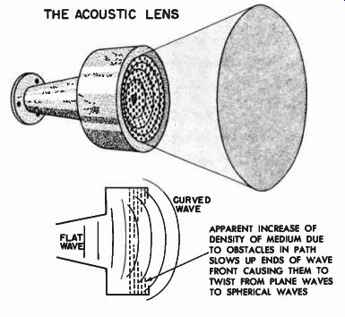
Fig. 3-18. The acoustic lens converts a plane wavefront to a curved
wavefront.
...wave being retained momentarily while the next one came in on top of it. There is thus an apparent increase in the density of the medium (in the vicinity of the obstacle array) through which the sound wave must travel. Since the velocity of sound decreases as the medium through which it flows increases in density, the speed of sound when passing through the array becomes less than that of sound in free space. If now the obstacle array is fashioned so that it slows up only a portion of the wavefront, the wavefront will be bent and the direction of the propagation will be changed. Inspection of Fig. 3-18 indicates how this differential slowing up of the wavefront at its edges causes the overall direction of the front to become more circular and consequently more spread out.
Since the scattering effect of the acoustic lens is a function of many critical factors concerning the spacing of the obstacles, the size of the obstacles, and the frequency involved, it will be found that the dispersion produced will have large side lobes of energy, which in some cases exceed the amplitude of the on-axis response. The acoustic lens thus furnishes wide angle response, but at the expense of some smoothness of response in the desired plane of dispersion.
The Reciprocating Flare Horn
The reciprocating flare horn accomplishes wide angle distribution of sound through the expedient of reversing the direction in which the pressure builds up within the horn and maintaining a mouth configuration that minimizes undesirable diffraction in the vertical plane.
All horns are pressure controlling devices. At the throat of the horn the pressures are greatest; at the mouth they are the smallest. At any point along the horn between the mouth and the throat, the sound pressure will be of some value intermediate between these two extremes. The manner in which the sound pressure throughout the horn will vary depends upon the growth of the cross-sectional area of the horn. Thus, by controlling the manner in which the horn expands, it is possible to "contour" the sound pressure into any direction. To perform useful acoustic work, however, the sound pressures built up within the horn must emerge into space through the mouth of the horn.
The mouth of the horn thus becomes the actual sound radiator. Thus the size and configuration of the horn mouth in conjunction with the horn flare, and together with the frequency involved determine the degree of dispersion.
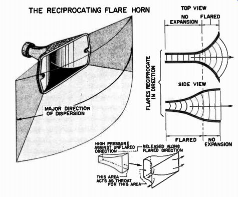
Fig. 3-19. The reciprocating flare horn builds up high pressure against the
walls in un-flared direction; pressure is then released into the front flared
section to produce uniform wide angle dispersion.
The reciprocating flare horn is one in which the rate of expansion of the horn remains constant, but the direction in which it expands changes from one plane to another for purposes of contouring the pres sure fronts within the horn. Reference to Fig. 3-19 will indicate that the reciprocating flare horn first expands rapidly in the vertical direction with practically no expansion in the horizontal direction. A cut taken across this first horn section would show it to be a fairly well elongated rectangle oriented vertically. The sound pressure traveling down a channel of this type of cross-section finds it relatively easy to expand into the vertical direction, for the walls flare away in that direction. In trying to expand into the horizontal direction, however, the sound pressure meets the side walls of the horn, which restrict the wave from expanding, and consequently the sound pressure finds itself building up at these side walls rather than being allowed to freely expand. We might therefore say that looking into this rectangular section of the horn, there are high pressures against the un-flared vertical walls, and low pressure against the flared horizontal walls of the horn.
Now, any one cross-section of a horn may be considered to be the "throat" area of the horn section in front of it; that is, one section feeds the next, and so forth. Thus we may look upon one horn section as the "driver" for the next section, with the very important attribute that it is a driver that is pushing greater sound pressure against the side walls than against the top and bottom walls. If, at some discrete point along the horn, we change the direction of the flares so that there is little expansion into the vertical direction and more into the horizontal direction, we have in effect a new horn with a flared directional advantage for horizontal dispersion, energized by a "driver" with already existing high sound pressure against the vertical walls anxious to be relieved into the horizontal direction. The overall effect of this reversal of the flare direction and the differential pressures at the throat of the reversed section contributes to exceptionally wide horizontal dispersion.
In the design of the horn, care is taken to so proportion the horn expansion that the final mouth of the horn is large compared with the wavelength of the frequency to be radiated. By this precaution, mini mum diffraction of energy into the vertical plane takes place; it is all concentrated into the horizontal plane. In consequence of the energy being restricted from radiating into the vertical direction in free space and being concentrated in the horizontal plane, the overall efficiency of the horn is increased. In consequence of the combined design of the reciprocating flares of the horn, its mouth configuration, and total lack of cells or fins, the reciprocating flare horn delivers high efficiency wide angle response of the entire high frequency spectrum without acoustical losses due to diffraction or irregularities due to beaming.
In summary, we see that because of the restricted range in which they are designed to work, tweeters may be made quite specialized in their design. They may be made more efficient, and features highly desirable for high frequency applications may be incorporated. These features are obtained from small light moving diaphragms with tight suspensions producing high natural resonance. They usually are of the sealed compression unit type, operating with horn loaded systems de signed for high efficiency and wide angle response.
The Midrange Speaker is a " Band Pass" Speaker
There are many good high fidelity systems that consist only of a woofer and a tweeter. The more elaborate systems utilize in addition a midrange speaker for even more controlled acoustic performance.
A WIDE ANGLE MID RANGE PROJECTOR FOR USE WITH A COMPRESSION TYPE DRIVER UNIT, SHOWING HALF SECTION VIEW
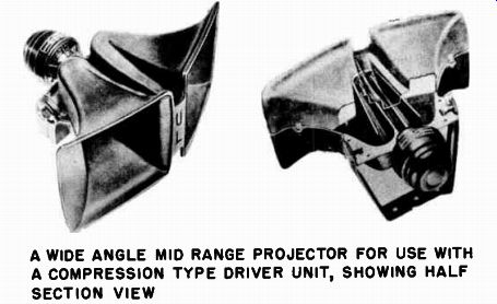
Fig. 3-20. For low frequency extension of the midrange horn projector,
the reflex type of structure gives good horn length in small space for
high efficiency operation with compression type driver. ( Courtesy University)
This midrange unit may be either a cone speaker or a horn driven system. Its design is again covered by the principles that control loudspeakers in general, but in this instance, they are adapted to more specialized designs, because of the restricted range over which the mid-frequency speaker is to perform. Those factors governing the choice of the type of mid-frequency loudspeakers are integrally tied up with the overall design of the system, because such speakers must bridge the gap between the woofer and the tweeter and must be de signed to be compatible with them. Therefore, the more detail consideration of the midrange speaker will be presented in section 6, which covers multi-speaker system design. We may treat the midrange speaker more generally at this point so that it may be fitted into the complete picture of these hi-fi variations from the basic types.
Midrange Speaker Range Determined by Woofer and Tweeter Limits
The midrange speaker begins to operate in that frequency region where the upper range of the woofer section becomes attenuated either by itself or through the intermediate devices of networks. Thus the expected low frequency response of the midrange speaker is usually fairly high in the acoustic spectrum. The upper range of the midrange speaker is governed by the lower range coverage of the tweeter, for the midrange unit generally need go up in frequency only far enough to provide a smooth overlap with the tweeter range.
The midrange speaker may be either a direct radiator cone speaker or a compression driver horn loaded system. The choice will be governed by the design of the system as a whole. If the woofer and tweeter sections of the system are direct radiator cone types, a midrange speaker of the cone type will match them in efficiency and provide a balanced system. If the woofer and the tweeter are high efficiency horn loaded sections, the midrange unit should preferably be a horn type, although as we will see in section 6, there are other important considerations governing the choice of speaker components. If it is a cone type, the midrange speaker may preferably be of the wide range type so that it may be operated low enough in frequency to match the woofer and at the same time give good high frequency reproduction up to the area where the tweeter takes over.
In the case of the compression driver horn type of midrange projector, the low frequency extension is limited by its natural cutoff frequency, and its efficiency is governed by the length of the horn. Figure 3-20 shows a typical midrange horn projector designed to extend down to 350 hz. This horn, of the reflex type, provides a long acoustic column in a short compact space which results in a high efficiency de vice for use even in restricted sizes of enclosures. The high end performance of a horn system is determined, in general, by the number and type of bends of the horn, and by the driver unit performance. A driver unit for operation down to the low frequencies required of a typical midrange reproducer will be of such size as to compromise the extreme high end efficiency. However, since this upper end may be taken over by the separate tweeter, this compromise is perfectly accept able. In fact, the compromise breeds specialization. In order to get optimum performance over the restricted middle range, the horn driver system is designed for maximum efficiency within that range.
Summary
Woofers are low frequency reproducers, large in size and low in resonant frequency; tweeters are treble reproducers, light in size and high in resonant frequency, and usually of the compression driver horn loaded type; and in between the two are the midrange speakers, chosen on the basis of low end and high end response compatible with the woofer and tweeter portions of the reproducing system.