Speaker Performance Depends Mostly Upon Mechanical Design
The acoustic designs of the specialized hi-fi loudspeakers discussed in the previous sectionstem directly from the principles of good mechanical design. In that sectionwe touched briefly on diaphragm weight, diaphragm stiffness, and related matters simply to lay out the broad boundary conditions for the design of the various types of loudspeakers. In the present chapter, we will show how these general conditions are specifically met through the proper mechanical design of the component parts. We will see that even though the loudspeaker is a device to be used with electronic equipment, it has very little about it that is specifically electronic in nature. If we discount the few turns of wire on the voice coil, the entire loudspeaker is an integrated system of mechanical parts in motion relative to one another. The quality of performance of the speaker, the range of its frequency response, its sensitivity, its angular dispersion will, in large measure, be dependent upon the design and mechanical structure of its parts, and the precision with which these parts move.
It will come as a revelation to the newcomer to acoustics to learn that when the loudspeaker is working it may undergo stresses and strains far in excess of the stresses and strains that airplanes undergo in coming out of very steep fast dives. In analyzing these stresses and strains, we shall start with the diaphragm because the diaphragm is the major element; it is (more specifically) the one and only element that actually provides the sound we hear. The operating conditions prevailing about the diaphragm will naturally be determined by whether the speaker is a large woofer structure or a small tweeter structure. As we have seen, the woofer diaphragm is comparatively heavy and large and undergoes high degrees of excursion, whereas the tweeter diaphragm is small and light and undergoes restricted degrees of excursion. It will be only natural, therefore, to find a different set of mechanical properties for the woofer moving systems than for the tweeter.
Diaphragm Withstands Tremendous Mechanical Stresses
The electrical power fed to the voice coil of a speaker is trans formed into mechanical power, which moves the diaphragm, and the mechanical power of the moving diaphragm, in putting the air into vibration, is converted to acoustic power. For instance, it may be shown by acoustic calculations that a 12-inch diaphragm has to move to a peak excursion of 1/4-inch when vibrating at 60 hz in order to radiate one acoustic watt of power. When it reaches its peak excursion, it has to come to a complete standstill for an instant, and then start going backward to complete its vibration cycle. In other words, it has come out of its dive as the airplane does, and reverses its direction. By the laws of physics, it may be calculated that when the diaphragm comes out of its "dive," under the above power conditions, it experiences a maximum acceleration equivalent to 93 "g's." More astounding yet, if similar calculations were to be made for this speaker when reproducing 10,000 hz, we would come up with the fantastic figure of 2060 g's for its acceleration. When we consider that ordinary airplanes may virtually come apart when subjected to more than 10 g's, we must look with deep respect upon the vibrating paper diaphragm of a loudspeaker.
Diaphragm Stability Determined by Size, Shape, and Paper Stock
In order to ensure that diaphragms withstand these tremendous stresses and strains, great care must be exercised both in the design of their physical shapes and the selection of material out of which they are made. As shown in Fig. 4-1, a flat piece of paper supported at its edges will be rather weak at its center. It will readily give under the gentle press of one's finger. On the other hand, if that same piece of paper is rolled up into a conical shape and placed with its wide base down on the table, it is possible to exert considerable pressure upon the point of the cone before it collapses. If we apply this concept to loudspeaker diaphragm design, we find that, in general, the deeper the loudspeaker diaphragm, the more rigid it becomes, and the more it will move as one whole piston. This is actually the condition we seek ...
A FLAT PIECE OF PAPER SUPPORTED AT ITS EDGES WILL READILY SAG AND DISTORT UNDER PRESSURE APPLIED TO ITS CENTER A SHALLOW DIAPHRAGM WILL BE UNSTABLE FOR LARGE APPLIED VIBRATIONS
WHERE PISTON ACTION IS DESIRED THE SAME PIECE OF PAPER ROLLED UP INTO THE SHAPE OF A CONE WILL EXHIBIT GREAT STRENGTH WHEN A FORCE IS APPLIED TO ITS APEX A DEEP CONE WILL BE MECHANICALLY STABLE FOR LARGE APPLIED MOTIONS run WHERE PISTON ACTION IS DESIRED
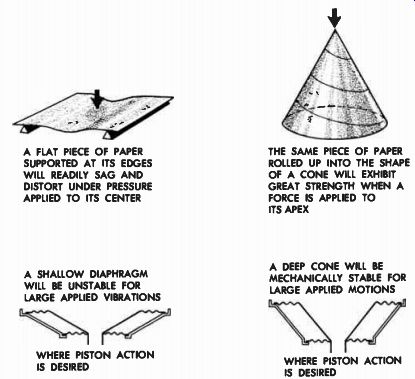
Fig. 4-1. Where complete piston motion of a diaphragm is required, maximum
mechanical stability may be obtained by a deep conical structure.
... in a woofer. We want the diaphragm to move as a whole without flexing of the vibrating surface itself so that we may get as much active radiating surface as possible. Therefore, we find that woofers, which have to move large volumes of air, obtain great mechanical stability by means of deep cone structures.
The stability of the cone is also greatly determined by the paper stock from which the cone is made. Almost all of today's hi-fi speakers use diaphragms compounded by a molding process or a flotation process by which it is possible to blend in the mixing vats many ingredients to get a paper stock that will perform in the acoustic manner desired.
Many kinds of fibers, cloth, wool, and paper go into the making of the diaphragm. By choosing the proper compound, we may get a soft-stock cone, or a hard-stock cone, or any variation between the two. Obviously, the type of stock used will also determine both the mechanical stability of the cone and its acoustical performance.
A soft material will not transmit a force as well as a hard material.
This is especially true where vibratory motion is concerned. The soft material acts as a cushioning factor for the force applied to it, and the higher the frequency the greater is this cushioning effect. Thus a loudspeaker cone made from a soft material will vibrate at its apex area when driven at its apex by a high frequency signal, but the rest of its diaphragm area will stand relatively still, due to the cushioning effect of the soft material along its body length. This cushioning pre vents the driving force from being transmitted to the body of the diaphragm as a whole. The soft material has been instrumental as a decoupling factor for the high frequencies. Actually, if the diaphragm material is of a very soft nature so that the high frequencies are lost even before they activate the apex area of the cone, the speaker will not reproduce the highs at all and the cone will be of the woofer class.
If the cone is made from a hard material, which transmits the vibrating forces throughout its body, there will be less uncoupling of the body of the cone, and the cone will tend to move as a piston for all frequencies. However, this also results in rather inefficient high frequency reproduction, because the diaphragm is too heavy to be adequately moved as a whole by the weak high frequency driving forces.
Thus a compromise must be made by the designer of the loudspeaker in the selection of paper stock for the loudspeaker on the basis of the expected balance between lows and highs and on the basis of whether the speaker is to be a woofer or a tweeter. (See Fig. 4-2.) Often the compromises between hard and soft material are quite visible to the eye.
Some cones appear to be treated in their apex area with a stiffening impregnation. This is usually referred to as an "apex dip." It is an application to the apex of the cone of a substance that flows into the fibers and stiffens them, thus producing a relatively hard but small apex area for good high frequency transmission. Beyond the treated area, the cone retains its soft state, and uncouples itself as far as the high frequencies are concerned, but remains fully active along with the apex for the reproduction of the low frequencies. Hence we see that between cone shape and cone material are many of the design parameters of the loudspeaker performance characteristic.
The loudspeaker manufacturer must compound a design (as far as shape and stock of cone are concerned) that will not only produce the proper acoustic response with maximum mechanical stability, but will also prevent cone "break-up." Break-up is a term applied to the tendency of a weak membrane to separate into separate vibrating sections ...
IN "SOFT" CONE, HIGH FREQUENCY VIBRATION IM PARTED TO APEX BECOMES QUICKLY DAMPED AND CONE DOES NOT REPRODUCE HIGHS. SOFT CONES ARE THUS USUALLY WOOFERS (B) IN "HARD" CONES, HIGH FREQUENCY VIBRATIONS ARE TRANSMITTED THROUGHOUT GREATER PORTION OF THE CONE, BUT DUE TO LARGE MASS OF CONE, HIGH FREQUENCIES WILL BE INEFFICIENTLY REPRODUCED THE RIGHT MIXTURE OF HARD AND SOFT INGREDI ENTS IN A CONE, ALONG WITH PROPER APEX DIP TREATMENT WILL PRODUCE THE PROPER HIGH FRE QUENCY ACTION AT APEX OF CONE, AND WOOFER ACTION FROM THE WHOLE CONE (C)
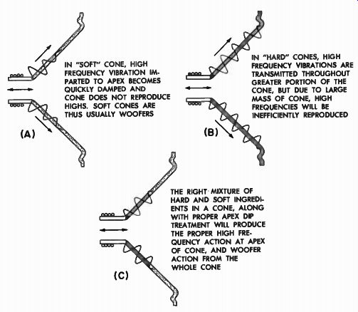
Fig. 4-2. The type of pulp formulation of the cone will determine its
acoustical performance, as well as its mechanical stability.
... (Fig. 4-3) where the frequencies of these induced vibrations are not harmonically related to the main driving frequency. These spurious vibrations, because they are not harmonically related, result in a "cry" of a very unmusical nature, usually falling somewhere in the middle region of the musical spectrum. Such cone break-up may be partly controlled by cone material, cone shape, and cone reinforcement. This reinforcement may consist of structural ribs placed circumferentially about the midsections of the cone to apply a stiffening factor running over those sections which would normally tend to vibrate independently.
(See Fig. 4-4.) These strengthening ribs are put in not for appearance but for performance, and go hand in hand with diaphragm weight, shape, and stock in determining mechanical and acoustic stability.
THE SECTIONS MARKED "+" MAY MOVE IN ONE DIRECtion AND THE SECTIONS MARKED "-" MAY MOVE IN THE OTHER AS THE DIAPHRAGM VIBRATES BACK AND FORTH
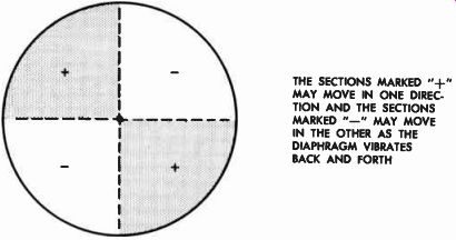
Fig. 4-3. Diaphragm "break-up" may occur in a weak vibrating
membrane, causing large sections of the membrane to vibrate at frequencies
not harmonically related to the fundamental. This results in cone "cry" at
the middle frequencies.
Woofers Need Large Deep Diaphragms, Tweeters Small Shallow Ones
Thus in woofers, where the diaphragm is large and moves as a whole with large excursions, we find deep cones for strength and rigidity during these large motions. However, in the case of cone type tweeters, where lightness of moving system is highly important, but …where, fortunately, diaphragm size is small and motion greatly reduced, the diaphragm may be made considerably shallower and of thinner stock. In contrast to the deep mechanically rugged and massive appearance of woofers, cone tweeters have a fiat-faced and frail appearance.
BODY OF CONE (UNFLEXING AREA); EDGE SUSPENSION (FLEXING AREA); THESE RIBS RUNNING AROUND THE CONE TEND TO STIFFEN THE CONE CIRCUMFERENTIALLY TO REDUCE CONE " BREAK-UP"
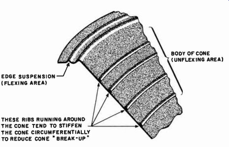
Fig. 4-4. Cone break-up may be minimized by the application of stiffening
ribs as well as proper diaphragm weight, shape, and stock.
In the case of the compression type driver units, the diaphragms are usually made of molded, laminated phenolic impregnated woven cloths. Diaphragms of this nature are molded under pressure and, in addition, are considerably smaller than direct radiator cones. Hence these may be designed to give extreme mechanical rigidity with lightness of weight. This makes for overall increased efficiency and clean ness of response.
Diaphragm Suspension Must be Linear
Thus far we have been discussing the mechanics of the diaphragm itself. However, the diaphragm must be supported in its basket by means of its "rim compliance," or edge suspension, as shown in Fig. 4-4. It will be recalled that the heavy woofer cone is comparatively lightly suspended in order to realize the necessary low resonance frequency. "Lightly suspended" means that the paper spring or compliant rim around the edge of the cone, which holds it to the basket, is very loose. One very important characteristic that every rim compliance must have is that of linearity; it must stretch evenly. If it were to pull out too tautly while the cone tried to continue its motion, the motion of the cone would become "flat-topped" and nonlinear motion would result, introducing undesirable harmonic distortion. This is illustrated in Fig. 4-5. Thus we see that a term normally applied to electronic devices is in this case the result of mechanical design of a speaker.
By providing many folds in the paper (Fig. 4-6A), linear spring action may be obtained, so that the diaphragm may move out fully to its maximum position without stretching the spring beyond its linearity limits. It might appear that the larger the spring the better. Not so, however. If the spring is made up of many folds, we immediately remove considerable active area from the overall diaphragm, leaving less active piston area. Secondly, the large spring begins to exhibit a resonance of its own because it also has its own mass, with the result that somewhere in the middle frequencies the larger rim compliance and the diaphragm piston may actually vibrate out-of-phase with one another. Thus a depressed area in the frequency response, usually referred to as edge resonance effect, will occur (Fig. 4-6C). In order to minimize this effect, the rim compliance may be designed to be small in area, but with large spring loop as shown in Fig. 4-6 (B). Although this expedient will eliminate much of the edge resonance effect, it has the disadvantage that, because the edge is restricted, its motion can not be maintained as linear as with the larger spring. Here again, compromise must be made, and the acoustic conditions of operation are once more determined by the mechanics of how well a piece of fibrous material may be flexed.
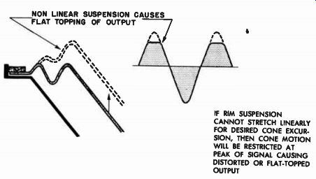
Fig. 4-5. For clean peak signal reproduction, edge suspension must
have mechanically linear motion for full diaphragm excursion. NON LINEAR
SUSPENSION CAUSES FLAT TOPPING OF OUTPUT
IF RIM SUSPENSION CANNOT STRETCH LINEARLY FOR DESIRED CONE EXCUR SION, THEN CONE MOTION WILL BE RESTRICTED AT PEAK OF SIGNAL CAUSING DISTORTED OR FLAT-TOPPED OUTPUT
Minimizing Rim Resonance Effect
This edge resonance may be minimized by treating the rim compliance with a mechanically resistive material that will effectively dampen the self resonance of the rim area. One very successful means of accomplishing this damping is to coat the edge compliance with special compounds that are "dead" and have no resilience, compounds that tend to stay where they are put. When such a material is applied to the edge of the cone, it imparts its characteristic lack of resilience to the rim, so that even though the rim may still want to vibrate at its own natural resonance, it does so very sluggishly, with the result that edge resonance effects are generally reduced. This edge treatment is easily recognized by the shiny surface that covers the rolled section of the diaphragm. Another means of accomplishing this damping effect is to cement sections of resistive material (such as rubber) over the compliant area sections to provide mechanical damping of these areas.
Thus a judicious choice of the edge roll configuration, with proper damping added to it, will give maximum linearity of motion with minimum edge resonance effect.
----------
12" REDUCED PISTON '1 1 h ° ENLARGED PISTON
A COMPLIANCE MADE FROM MANY RIM FOLDS WILL BE LINEAR BUT CAUSE CONE TO VIBRATE ERRATICALLY OFF ITS AXIS. IT ALSO RESULTS IN A REDUCTION OF ACTIVE PISTON AREA, AND CAUSES SEVERE EDGE RESONANCE EFFECTS, WHERE LARGE EDGE VIBRATES BY ITSELF OUT OF PHASE WITH MAIN PISTON
A COMPLIANCE MADE FROM FEWER FOLDS WILL TEND TO BE LESS LINEAR, BUT WILL GIVE MORE STABLE CONE MOTION, MORE ACTIVE PISTON AREA, AND LESS EDGE RESONANCE EFFECT EDGE RESONANCE EFFECT DUE TO LARGE EDGE AREA VIBRATING OUT OF PHASE WITH MAIN BODY OF CONE FREQUENCY (C)
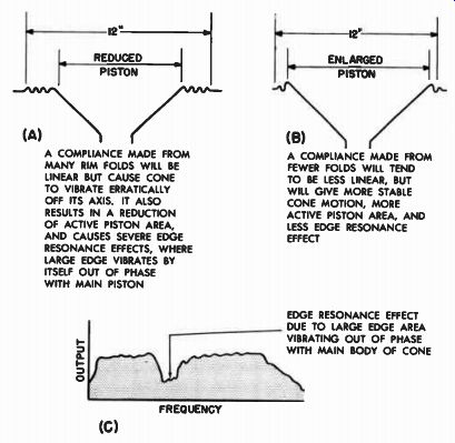
Fig. 4-6. The design of the rim suspension must give good mechanical
linearity, but not at the expense of smoothness of response or vibrational
equilibrium of cone.
-------------
Woofer Voice Coil is Large, to Dissipate Heavy Audio Power
Due to the fact that most acoustic power resides in the low frequencies, woofers must be designed to produce large amounts of acoustic power. However, they must accordingly be able to take large amounts of electrical power. No piece of machinery is 100 percent efficient. There are losses of power in all physical systems, and loud speakers are no exception. A great proportion of the electrical power fed to a loudspeaker is not converted into acoustic energy. It is lost as heat or in other ways. The voice coil structure of a woofer must be designed to dissipate large amounts of heat, or it may suffer serious damage and cause failure of the loudspeaker. Accordingly, we find that the voice coils of woofers are usually large in diameter, at least 2 inches, and that the coil is wound of comparatively heavy wire so that maximum dissipation of heat may be accomplished. However, there are limits to the size of coil that may be designed. Obviously, we could design a large massive coil that would easily accept and dissipate all the heat we required. However, when we realize that in addition to dissipating heat, the coil has to move itself under its own force, it will be realized that sooner or later we would have good heat radiation but, due to the massiveness of the coil, no motion and no sound. There is a definite relationship between the weight of the coil and the weight of the diaphragm for optimum acoustic performance, which determines the overall size of the voice coil for a given weight of diaphragm.
Within this general size, the loudspeaker manufacturer must de sign his voice coil structure to give optimum acoustic output with most efficient electrical power handling capacity. Since metals are good conductors of heat, voice coils wound on dural coil forms add to the effective heat dissipation of the coil by absorbing the heat from the coil through conduction. The large dural surface of the voice coil form then radiates the heat into the surrounding iron parts of the speaker structure.
Power Capabilities Depend Also Upon Diaphragm Stability
The power handling capacity of a loudspeaker is not a function only of the heat its voice coil can dissipate electrically. Its power rating is also governed by the ability of the vibrating system to withstand continuous cyclic motion without physical change. Thus, even though a loudspeaker voice coil may be able to take 25 watts of electrical power, the diaphragm itself may move so violently that its compliant edge quickly cracks or tears away, or the voice coil may ride erratically in the air gap of the magnet and scrape itself to destruction against the walls. Thus power handling capacity is an overall figure that must cover not only the electrical characteristics but the physical characteristics of the speaker as well. The mechanical power handling capacity of the cone itself is usually determined by the design of the rim compliance and the ability of the cone to vibrate without acoustic break-up.
If the rim is designed to be able to withstand constant and excessive flexing without breakage, the diaphragm as a whole will last for the life of the speaker.
--------------
IF THE CONE TILTS WHEN VIBRATING, THE VOICE COIL WILL BE MISALIGNED IN THE GAP, AND VOICE COIL RUBBING WILL RESULT. ADEQUATE CLEARANCES CENTERING SPIDER SMALL GAP MUST BE KEPT BETWEEN COIL AND GAP SIDES TO PREVENT RUBBING. WHEN CONE TRAVEL IS STABILIZED (BELOW) GAP SPACING MAY BE REDUCED DIRECTION
VIBRATION STABILIZING SPIDER (B)
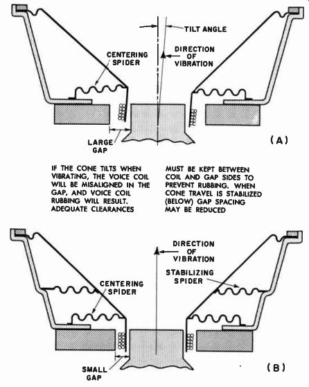
Fig. 4-7. Where mechanical vibration is precisely controlled, greater
magnetic gap efficiency may be obtained.
----------------
However, the mechanical precision with which the suspension holds the whole assembly together determines the mechanical longevity of the voice coil itself. The voice coil must be kept perfectly aligned mechanically in its magnetic gap at all times during its vibration cycle.
If, during its vibration, it sways or twists sideways, it may scrape itself against the walls of the gap, causing rubbing of the voice coil, which in turn results in distortion, in shorted turns, and sooner or later, in an open voice coil. Although the spider is normally the device that keeps the coil centered in the gap when no motion is involved, it is the combination of the spider and the outer cone suspension that dictates how the coil behaves in the gap under motion. Obviously, from Fig. 4-7 (A) it will be seen that, even though the spider may keep the coil centered, if the cone tilts, it will tilt the coil and cause rubbing. Where small motions are involved, as in tweeters, this condition does not present a problem. However, in the case of woofers, where voice coil motions of the order of 3 / 8 inch or more are prevalent, added insurance against voice coil misalignment may be had by the double spider suspension shown in Fig. 4-7 (B). The addition of the second stabilizing spider part way up the cone of the speaker acts as a second guide to the linear in-and-out motion of the voice coil, keeping the voice coil not only rigidly centered, but also moving in a rigidly proscribed axis.
In loudspeakers in which the voice coil travels a straight and narrow path, and in which the side play of the coil is rigidly controlled, the clearances between the overall gap walls and the voice coil may be reduced, with resultant improved magnetic circuit efficiency, because of the reduced gap cross-section. Thus we see again that the final acoustic performance of the loudspeaker is a function of the mechanical tolerances permissible between controlled moving parts.
RING MAGNET FLUX FLU X FILTER SCREEN SURFACE CONTACTS ARE NEVER PERFECT SO THAT MATING SURFACES IN A MAGNETIC CIRCUIT SUCH AS HERE INDICATED ARE ACTUALLY BREAKS IN THE MAGNETIC CIRCUIT. IN THIS CASE THERE ARE ACTUALLY FOUR SUCH BREAKS IN ADDITION TO THE GAP IN THE "W" MAGNET DESIGN, SURFACE CONTACTS ARE REDUCED TO TWO, INCREASING MAGNETIC CIRCUIT EFFICIENCY PUMPING ACTION OF DIAPHRAGM DOME CAUSES FORCED AIR COOLING OF VOICE COIL
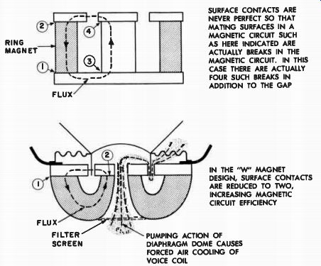
Fig. 4-8. Magnetic circuit efficiencies may be increased by reducing
number of surfaces.
Magnetic Circuit Construction Determines Gap Flux
In connection with magnetic circuits and their dependence upon mechanical design, a type of magnet structure has been developed that is designed for high magnetic efficiency, and which at the same time provides means of forcibly cooling the voice coil that rides in its magnetic gap. This is the "W" magnet illustrated in Fig. 4-8. In any magnetic circuit, the more breaks there are in the circuit, the lower is the efficiency. No matter how well two adjoining surfaces of a magnetic circuit are in contact, such contact is made only through a large number of small areas, because no surface is absolutely smooth. Thus, two facing surfaces are actually a break in the circuit, and even though it is small, this represents a loss of magnetic flux. There are usually four such contact breaks in the magnetic circuit, but in the "W" magnet assembly there are only two, and greater magnet efficiency is therefore made available.
The open center of the "W" magnet, working in conjunction with the apex area of the diaphragm, and closed by means of the dural cap, provides a forced cooling system for the voice coil. As the diaphragm pulses back and forth, the air is sucked in and out of the voice coil area through the rear filter screen.
Heavy Magnetic Circuits and Voice Coil Alignment Require Sturdy Baskets
The size of the magnet of a loudspeaker is, in a large measure, dependent upon the size of the speaker. Large woofers are driven by heavy magnet circuits of perhaps 7 to 10 pounds. These magnet circuits, which are invariably located at the very rear of the speaker, represents a heavy dead weight on the structure holding the entire speaker together.
If this speaker basket, or housing, is not properly designed, the weight of the magnetic circuit may cause the basket structure to be deformed to the extent that the entire alignment between diaphragm, voice coil,...
DOUBLE SPIDER ASSEMBLY STRUCTURAL GIRDER BASKET
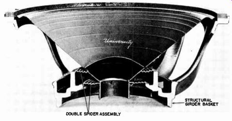
Fig. 4-9. Girder basket construction and double spider construction
en sure minimum basket deformation and precision voice coil alignment.
(Courtesy Audio Engineering Society. July 1954, "Mechanics of Good
Loudspeaker Design")
...and gap is upset. Furthermore, improperly designed housings may also become warped out of round when they are screwed down to irregular baffles or plates. This stressed warping of the basket causes misalignment of the voice coil in the gap. Today's loudspeakers, designed for good high acoustic output at low frequencies, call for more and more pounds of magnet. More pounds of magnet means greater strain on the supporting structure. Where the design calls for high conversion efficiency at low frequencies, it is desirable to build the basket as structurally strong as possible, so that it may carry the weight of the magnet necessary to power the speaker. Figure 4-9 illustrates in a cut away view the structural girder design that a modern loudspeaker should use to insure optimum resistance to mechanical stress on the basket structure.
Summary
We have now examined all the component parts of a loudspeaker, from the voice coil, which first receives the electrical impulse, down to the basket, which supports the whole assembly. Also, we have seen that those elements of design that are necessary to provide structural and motional stability for the loudspeaker also bring about improved acoustical performance. We must conclude that good loudspeaker performance can only stem from good mechanical design.