The horn is perhaps the oldest type of baffle in the art of acoustic reproduction. Edison's early phonograph had a short conical horn to amplify" the sound coming from the mechanically energized diaphragm. Later versions of this instrument sprouted the "morning glory" type of horn; and just before the advent of the electro-acoustic reproducer the console-type acoustic phonographs so well known in the living room and parlor of the 1920's boasted well-designed folded horns for "concert-hall reproduction." This type of horn gave good reproduction for the recorded material with which it had to work, and for the acoustic "tone box" feeding it.
When the day of electro-acoustic reproduction dawned upon us, it was only natural that the horn be used again. The most remembered types were offshoots of the "morning glory" variety, coupled to a large heavy driver unit on the table beside the radio. These driver units were actually overgrown models of telephone receivers. In fact, the unit was commonly referred to as a "loud speaking telephone." From that derivation we were left with the term "loudspeaker" for any device that makes sound loud enough so that the reproducer does not have to be held up to the ear for the sound to be heard. Despite the fact that the horn is of ancient vintage, it is a highly efficient device, acoustically speaking. With the modern studies that have been made of horn theory and design and the improvements in their driver units, the acoustic horn has taken a firm foothold in the high fidelity art.
SIMPLIFIED DIAPHRAGM HIGH PRESSURE SOUND FROM THE SQUEEZED INTO LOW PRESSURE TRANSFORMED DIAPHRAGM GETS TO THROAT AREA PRODUCING HIGH PRESSURE AT THROAT MOUTH Ti EXPANDING WAVE AIR COLUMN REDUCES PRESSURE
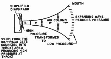
Fig. 10-1. Simplified horn structure illustrating transformation of high
pressure at throat to low pressure at mouth.
Horn Provides High Acoustic Efficiency
The acoustic horn is an acoustic transformer, not an amplifier, despite the fact that a source of sound appears louder when a horn is applied to it. The reason for the increase in sound output from a driver when it is coupled to a horn is that the horn, through its transformer action, creates a better impedance match between the driver and the air. With improved impedance matching of the driver unit to the air comes improved power output and efficiency of operation.
Horns may take many shapes, but they have one characteristic in common. They expand from a narrow opening called the throat to a larger opening called the mouth. (See Fig. 10-1.) The intervening space is called the "air column." When the horn is coupled to a driver unit at its throat, all the sound from the driver unit must travel into the throat area. This means that if the diaphragm of the driver unit located at the throat of the horn is five times larger than the area of the throat, the sound coming from the surface of the diaphragm must be compressed in a five-to-one ratio. As a result, the sound pressure at the throat of the horn is high.
As the sound wave progresses along the horn toward the mouth, it finds its confining walls continually expanding. This allows the high pressure wave to spread out over a larger and larger surface. As it spreads out, the pressure per unit area decreases. Finally, at the mouth of the horn, the sound wave breaks away from the mouth of the horn and is propagated into space. Thus the horn has acted as a transformer; it has changed the acoustic flow of energy from a high pressure condition at the throat to a low pressure condition at the mouth.
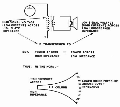
Fig. 10-2. Analogy showing the impedance transformation function of a
horn. HIGH SIGNAL VOLTAGE (LOW CURRENT ) ACROSS HIGH PLATE IMPEDANCE LOW
SIGNAL VOLTAGE (HIGH CURRENT) ACROSS LOW LOUDSPEAKER IMPEDANCE ----LOWER
SOUND PRESSURE
ACROSS LOWER IMPEDANCE --- BUT, POWER ACROSS = POWER ACROSS HIGH IMPEDANCE LOW IMPEDANCE THUS, IN THE HORN :-
Horn Couples High Throat Impedance to Low Mouth Impedance
This statement should now be interpreted in terms of impedance because it is the impedance into which something works that deter mines the power that is developed. We know that in electrical transmission systems or electrical coupling systems carrying a given power, if we have high voltage at one portion of the circuit and low voltage at another the high voltage exists across the high impedance portion of the circuit and the low voltage appears across the low impedance portion. Take for example the output transformer in Fig. 10-2. The primary side of the transformer, which is connected to the high signal output plate voltage (at low current) is of high impedance, while the secondary, which connects to the loudspeaker, is of low impedance, across which there is low signal voltage (at high current). Sound pressure is analogous to voltage. Voltage drives the current through the circuit; sound pressure imparts the "volume velocity" to the sound wave. Thus, in an acoustic transformer, high sound pressure exists across high acoustic impedance, and low sound pressure exists across low acoustic impedance. What happens in the acoustic horn is that the gradually tapering column of air is a means of matching the relatively low loading impedance of the nebulous outside air to the relatively high mechanical impedance of the comparatively massive vibrating piston. When this impedance match is properly made, the combined driver and horn system may operate at considerably higher efficiency.
Putting it in simple terms, the direct radiator type of loudspeaker used in a simple baffle must "grab hold" of the entire air merely through the air with which the surface of the diaphragm itself comes in direct contact. Because the diaphragm size is always relatively small compared to "all the air," the impedance match is a poor one and the efficiency of the direct radiator system is correspondingly low. In the case of the horn, however, the diaphragm is allowed to contact a "surface" of air much larger than its own area by means of the much larger horn mouth, which is directly coupled to the diaphragm through the horn.
The larger the mouth of the horn, the better the impedance match between "all the air" and the diaphragm, and the more efficiently the diaphragm can grab hold of the air. As a consequence, the horn system has high efficiency, somewhat in the order of 40 to 50 percent, whereas direct radiator efficiency is in the order of 10 percent or less.
The mouth of the horn may be considered to be an actual vibrating piston by itself. If reference is made to Fig. 9-1, it will readily be seen that by making the mouth of the horn large for a given low frequency a much larger radiation resistance may be presented to the relatively small diaphragm driving the large mouthed horn. This is illustrated in Fig. 10-3.
High System, Efficiency Reflects Itself in Cleaner Reproduction
Because of the high order of efficiency of the horn-loaded system, it is possible to obtain much more linear low frequency response than with a direct radiator system driven to produce the same amount of acoustic output. The power output of a vibrating diaphragm is a function of the size of the diaphragm and its displacement. The more the diaphragm moves away from its equilibrium position, the more air it is pulsing, and the higher the acoustic output. Thus, if two identical diaphragms were installed, one in a horn and the other in a direct radiator enclosure, the latter diaphragm would have to vibrate much more violently than the one in the horn system to produce the same amount of acoustic power output. When a diaphragm vibrates too energetically, it may leave the linear portion of the magnetic field in which its voice coil is balanced, with the result that it will move into areas of magnetic nonlinearity for heavy signals, resulting in distortion.
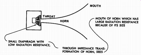
Fig. 10-3. Small diaphragm is better match to "all the air" through
the horn as an impedance transformer. THROAT SMAL. DIAPHRAGM WITH LOW
RADIATION RESISTANCE, MOUTH; MOUTH OF HORN WHICH HAS LARGE RADIATION RESISTANCE
BECAUSE OF ITS SIZE THROUGH IMPEDANCE TRANS FORMATION OF HORN, SEES
Also, large excursion of the diaphragm may cause the diaphragm to pull the centering spider out beyond its elastic limits and cause further nonlinear distortion of the waveform. It should, of course, be realized that we are here painting a rather dark picture of the direct radiator system as compared to the horn system. Actually, these deleterious effects appear only when very large audio outputs are demanded from the relatively inefficient direct radiator system. Hence, in large auditoriums and theaters, where high sound power with minimum distortion is required, we invariably find horn loaded systems.
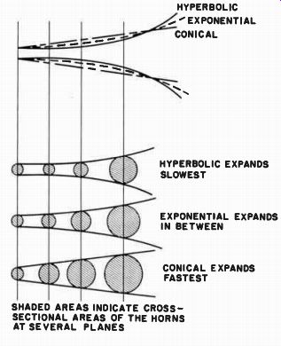
Fig. 10-4. A comparison of the rates of expansion of hyperbolic, exponential,
and conical horns all having the same theoretical cut off frequency. ----------
SHADED AREAS INDICATE CROSS SECTIONAL AREAS OF THE HORNS AT SEVERAL PLANES
HYPERBOLIC 'EXPONENTIAL CONICAL HYPERBOLIC EXPANDS SLOWEST EXPONENTIAL
EXPANDS IN BETWEEN CONICAL EXPANDS FASTEST
Shape of Horn is Determined by Frequency Range Reproduced
The shape of the horn is all important in determining the function and efficiency of the horn. There are horns for low frequency reproduction and horns for high frequency reproduction, and their designs are radically different. Horns for high frequency work, in addition to being small in size, have many forms of compensation built into them for better wide angle dispersion of the high frequencies. Horns for low frequency reproduction are not affected by dispersion problems, because low frequencies spread out rather evenly without any auxiliary devices. Secondly, low frequency horns are usually large and massive, high frequency horns small and compact. The difference in their relative sizes is not simply an arbitrary matter. Horn design must employ precise, mathematically determined expansion rates for proper performance in the desired frequency band.
Horns are essentially high-pass filters. They pass a band of frequencies above the cutoff frequency. Once this theoretical cutoff frequency has been chosen, the development of the horn is a straight forward geometrical layout. Horns may flare out rapidly or they may flare out slowly. The rate at which they "grow" is determined by the family of horns to which they belong, and by the low frequency cutoff desired from the horn.
There are several types of horn in use as acoustic reproducing elements. However, despite the fact that they are all high-pass filters, they do not necessarily follow the same laws of geometric expansion (even though they may all have the same theoretical cutoff frequency). The two most prevalent types are the "exponential" and the "hyperbolic" (actually, hyperbolic exponential or "Hypex"). These terms are the more popular designations for them; actually, the mathematician will readily recognize that exponential and hyperbolic devices belong to the same family of curves.
For the layman, however, the two general classifications noted specifically refer to two types of horns, which expand to different degrees for the same cutoff frequencies. The fact that two different types of horn accomplish the same end result, as far as pass characteristics are concerned, leads to the conclusion that the differences in operation are not a matter of frequency. Before we discuss these differences in operation, let us examine the manner in which they differ geometrically.
Comparison of Conical, Exponential, and Hyperbolic Horns
Figure 10-4 illustrates the manner in which the cross-sectional area of the exponential and hyperbolic horns differ for a given increase in the length of the horn, where both horns have the same cutoff frequency.
Along with these is shown another horn, the conical, which will come into later discussions of the characteristics of these horns. From this figure it will be observed that, for a given length of horn up to the point where the mouths of the three horns are all equal, the hyperbolic horn expands at the slowest rate, the exponential at a faster rate, and the conical at the most rapid rate. This matter has significance in relation to the level of reproduction at the area very near the theoretical cutoff point, and to the distortions to be expected from various types of horn as well as the amount of space taken up by them.
Figure 10-5 illustrates the acoustic radiation resistance of these three types. It will be noted that the horn with the slowest rise in radiation resistance in the pass band (which also means poorest low frequency response) is the conical. Next comes the exponential, which rises quite sharply and attains the maximum value quite soon. Last is the hyperbolic, which rises immediately at the cutoff frequency to a value of radiation resistance above the optimum and then drops down to the optimum at the same frequency as the exponential type. It is apparent from these curves of radiation resistance that the hyperbolic horn would be the best reproducer of low frequencies close to the cutoff point, the exponential second best, and the conical last. For this reason, the conical is never used as an acoustic reproducing device, except in the form of a simple handheld megaphone, which may be made cheaply by simply rolling up a piece of heavy fiberboard.
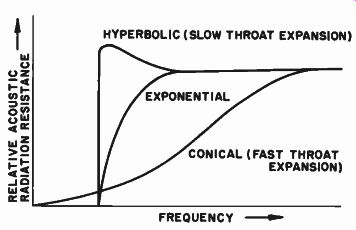
Fig. 10-5. Relative acoustic radiation resistance of conical, exponential,
and hyperbolic horns, indicating that the rise of the radiation resistance
of the horn varies inversely with the rate at which the throat area expands.
What then determines which of the two remaining horns -- the hyperbolic or the exponential -- is to be used? The fact that they are both used is evidence that there is an honest difference of opinion about the two. Let us examine a seldom appreciated fact concerning horns.
Although it is true that with horn loading a system may be designed to give low overall distortion because of the higher efficiency of the system (which in turn allows the energizing diaphragm to move much more conservatively), there is distortion introduced by the horn itself.
The horn, because of the manner in which it functions, introduces distortions of its own, depending upon the degree of constriction over the narrow first part of the horn, and the sound pressures that are being forced through this narrow section.
Horns Introduce Distortion at High Pressure Throat Sections
Nonlinear distortion is produced in this first constricted section of the horn because of the unequal expansion and compression of a gas (air) volume for a given change in pressure. A simple analogy illustrating this principle is shown in Fig. 10-6. Here we have shown a simple piston type of air pump, similar to the automobile tire pump once included as standard equipment with every car. In section (A) of the illustration, the piston is shown near the top of the pump cylinder with the air inside the pump near atmospheric pressure. Now let us move the piston back and forth just a very slight amount. Under these conditions the amount of compression of the air within the pump will be small, and little resistance to the in-and-out motion of the piston over this small distance of travel will be presented to the piston by the slightly compressed gas. Now, however, let us move the piston way down, severely compressing the air to a small proportion of its original volume. It will then become progressively harder and harder to push the piston down because of the high internal pressure of the compressed air pushing back on it. On the other hand, it will be relatively easy to pull the piston back up because of the comparative absence of pressure on the outside of the piston. Thus there is nonlinearity of motion of the piston in opposite directions for equal applied forces in those directions. It is obvious that the smaller the cavity into which the piston works, the faster will the pressure in that cavity increase for a given motion of the piston, and the greater will be the resultant non linearity of motion of the piston.
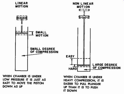
Fig. 10-6. An analogy indicating the non-linearity of piston motion when
piston works against a high pressure on one side and a low pressure
on the other. --------- LINEAR MOTION - SMALL
MOTION SMALL DEGREE OF COMPRESSION WHEN CHAMBER IS UNDER LOW PRESSURE IT IS JUST AS EASY TO MOVE THE PISTON DOWN AS UP NON LINEAR MOTION EASY HARD LARGE DEGREE OF COMPRESSION WHEN CHAMBER IS UNDER HEAVY COMPRESSION, IT IS EASIER TO PULL PLUNGER UP THAN IT IS TO PUSH IT DOWN.
Now how does this apply to the horn loudspeaker? Examination of the method in which the horns expand (Fig. 10-4) will show that the horn with the largest volume (hence lowest pressure) near the piston location is the conical. The horn with the smallest volume (hence highest pressure) in the throat section is the hyperbolic. Be tween these two extremes is the exponential. It would be expected that the conical horn would exhibit the least distortion due to built-up pressure, the hyperbolic the most distortion, and the exponential a degree of distortion between the two. It must be noted, of course, that this is distortion contributed solely by the horn itself and not by the driver unit.
One must, therefore, make a compromise between horns on the basis of their response and their distortions. These air nonlinear distortions become larger with greater pressure in the constricted areas.
Thus we may generalize as follows: the tighter the throat section and the higher the pressure in this throat section, the higher will be the resultant horn distortion. Hence, if a horn system is to be working at low level with equivalent low internal horn pressures, we may utilize the tighter horn, the hyperbolic, to get the most efficiency at the low end of the pass band with small horn distortion. If, however, heavy momentary bursts of high level sound (high power) are fed to the horn, the distortion for these bursts will be higher.
Now let us consider the exponential horn under the same conditions. If the system is working at low level, it may not have quite the extreme low end efficiency of the hyperbolic, but its output will have lower distortion. Sudden bursts of low frequency power will be reproduced with considerably less distortion than in the case of the hyperbolic horn. In view of the fact that horns in general are high efficiency units, and that considerable acoustic power is developed within them, it seems that some slight loss of the very extreme lows may be accepted at the advantage of lower overall horn-induced distortion. Consequently, the exponential horn is a happy compromise between efficiency and distortion. However, where distortion is not the determining factor, and considerable low frequency output is demanded from the system, the hyperbolic horn may be used.
In view of the fact that the hyperbolic horn throat section is under greater compression than the exponential type, it becomes necessary that much greater accuracies be adhered to in its construction.
Horns are Aided by Room Corner Placement
There are differences in woofer horns other than the manner in which they expand. There are specific advantages to the placement of an enclosure in the corner of a room. Corner operation is especially beneficial if the enclosure is of the horn type. Consequently, there are corner horns designed to work specifically and only in corners, such as the Klipschorn and the Lee Catenoid horn. These structures are actually folded horns built so that the outer side walls of the horn are the walls of the room. The horn intended only for corner use is not a complete horn when removed from its shipping carton. The side pieces appear to be missing. Actually, the horn is incomplete as received, but not as used. In operation, the unit is placed in the corner of the room so that the walls of the room act as the side panels of the unit, thus completing the horn. In the "corner-less" corner horn, as typified in the University "Dean," the unit as unpacked is a complete horn, all side panels being a permanent part of the structure. Thus, even when placed in the center of a wall, the unit acts as a complete horn without the benefit of corner loading. Naturally, when put into the corner, this horn is still complete in itself, but in addition it uses the radiation characteristics of the corner to enhance the low frequency reproduction.
Another difference between the corner-dependent and self-contained horns is that the corner-dependent variety consists of two air columns folded side by side, finally terminating in two mouths lying along the wall areas, while the self-contained type is a single folded air column that terminates in one mouth coupling to the floor and the walls. This matter of coupling to the walls of the room is important in connection with room acoustics. The manner in which these horns work in conjunction with the room will be treated in Part 3.
Horn Design Data
Although the exact relationships by which the actual expansion rates for these various types of horn may be found are beyond the scope of this treatment of the subject, it is easy enough to present design data in tabulated form to guide the man who desires to build his own woofer, horn. The table in Fig. 10-7, which will be discussed in more detail shortly, gives the percentage increase in cross-sectional area per unit length for a given cutoff frequency for the exponential horn, and the suggested minimum mouth dimensions for that frequency. It is suggested that the home constructor apply his skill to the type of horn that is easiest to build - the single-air-column folded horn terminating in a single mouth. Construction details for this type of horn are given in the appendix.
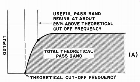
Fig. 10-7A. Response of exponential horn. --------- THEORETICAL CUT-OFF
FREQUENCY USEFUL PASS BAND BEGINS AT ABOUT
ABOVE THEORETICAL CUT OFF FREQUENCY
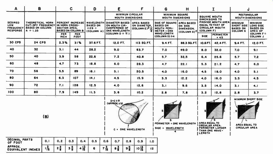
Fig. 10-7B. Exponential horn expansion rates and mouth dimensions for
various cutoff frequencies.
-------------
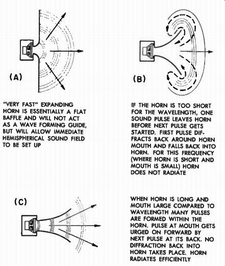
Fig. 10-8. The radiating efficiency of a horn depends upon its length
and mouth diameter as compared to the wavelength of the sound.
"VERY FAST" EXPANDING HORN IS ESSENTIALLY A FLAT BAFFLE AND WILL NOT ACT AS A WAVE FORMING GUIDE, BUT WILL ALLOW IMMEDIATE HEMISPHERICAL SOUND FIELD TO BE SET UP (C) IF THE HORN IS TOO SHORT FOR THE WAVELENGTH, ONE SOUND PULSE LEAVES HORN BEFORE NEXT PULSE GETS STARTED. FIRST PULSE DIF FRACTS BACK AROUND HORN MOUTH AND FALLS BACK INTO HORN. FOR THIS FREQUENCY (WHERE HORN IS SHORT AND MOUTH IS SMALL) HORN DOES NOT RADIATE WHEN HORN IS LONG AND MOUTH LARGE COMPARED TO WAVELENGTH MANY PULSES ARE FORMED WITHIN THE HORN. PULSE AT MOUTH GETS URGED ON FORWARD BY NEXT PULSE AT ITS BACK. NO DIFFRACTION BACK INTO HORN TAKES PLACE. HORN RADIATES EFFICIENTLY
---------------
Low Frequency Horns Expand Slowly, are Long, and Have Large Mouths
It will be observed from Fig. 10-7 that the lower frequency horns "grow" at a much slower rate than the higher frequency horns. A simple physical explanation may be given for this condition to provide a basis for the understanding of what goes on within the horn structure.
In a very general sense, we may consider the horn somewhat as a guide for the development of the acoustic wave. With this waveguide concept in mind, let us start with an extreme horn such as that shown in Fig. 10-8(A), which has such a sudden "flare" that it is almost a flat baffle with a hole in the center rather than a horn. Perhaps it may seem surprising to find this structure being called a horn. It may be considered to be just that - a horn with an exceedingly rapid rate of expansion - it grows so fast it virtually flattens out before it has had a chance to go anywhere. It may be parenthetically pointed out that this apparent indecision as to whether to call this a baffle or a horn is really no indecision at all. We must recognize the fact that a horn is a baffle. Once this fact is accepted, much confusion concerning baffles and enclosures will be eliminated.
However, let us get back to our suddenly expanding "flat" horn.
How will this flat horn perform as a guide for acoustic energy? Obviously, it is no guide at all. As soon as the wavefront of acoustic energy is thrown off from the diaphragm, it will immediately tend to spread out from the hole (throat) area in a hemispherical pattern that will, generally speaking, be sharpened as the frequency goes up.
Now let us close the horn down so that it looks more like a horn, by reducing its rate of flare (Fig. 10-8B). In this case, as soon as the wavefront leaves the diaphragm and is developed at the throat of this less rapidly expanding horn, it tends to travel down whatever length of horn has been presented to it. If the wavelength of this sound is such that before the next wavefront from the diaphragm reaches the throat of the horn the first pulse has found its freedom on the outside of the horn, this first pulse will begin to diffract back around the edges of the horn and "fall back" into the horn. For this frequency then, the horn does not exist. But now, without changing the horn, let us increase the frequency of the sound. Again, the first pulse will start traveling down the horn as shown in Fig. 10-8(C). Now if the frequency is made high enough, a second wavefront pulse will come into the horn before the first has had a chance to get out of its way. There may thus be two (or more) pulses within this same horn for this higher frequency before a pulse reaches the mouth of the horn. The forward pulse will then be forced outward, as it were, by the succeeding pulses (which prevent it from falling back into the horn). A wave guide action has been set up within the horn for this frequency. Thus for this particular horn, with an arbitrary rate of flare, the higher frequencies see the structure as a horn, but low frequencies do not. This is the high-pass filter action of the horn.
Since low frequencies are longer in wavelength, for reasonable waveguide action to be set up within the horn it must be comparatively long, and must expand slowly so that the pulse train may be set up before the horn mouth is reached. Thus low frequency horns are long, and flare slowly, while high frequency horns are short, and flare rapidly.
There is one other important requirement of horns in respect to the frequencies they pass. For a circular horn, the mouth diameter must be at least one-third the wavelength of the sound to be transmitted from the horn. This is predicated upon the circumference of the horn being a full wavelength. Regardless of whether the taper is mathematically correct for a particular frequency, if the mouth is too small, that frequency will not be transmitted properly. Thus in low frequency horns we find large mouths, and in high frequency horns we find small mouth. If we think in terms of the horn allowing a set of pulses to be developed, we will see that a quickly flaring short horn with small mouth will transmit only higher frequencies, while a slowly flaring long horn with a large mouth will pass lower frequencies. The exact frequency where the transition between pass and no-pass occurs is the theoretical cutoff point of the horn.
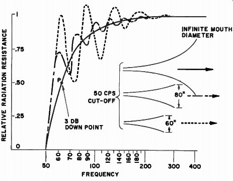
Fig. 10-9. Relative throat impedances of finite horns compared with a
perfect (infinite) horn. As the mouth gets smaller, the radiation resistance
becomes increasingly more irregular but with some response peaks above
that of the perfect horn.
In choosing a horn for a particular application, attention must be given to the chosen cutoff frequency. It must be remembered that every horn has its design cutoff frequency. However, the horn is not usable down to this frequency, because the output of the horn drops rapidly as the theoretical cutoff point is approached, as has already been shown in Fig. 10-7.
Thus far we have discussed the general differences in shapes of horns in terms of flare, length, and mouth size, and have seen that the low frequency horn is long, with a slow flare and a relatively large mouth compatible in dimension with the wavelength of the low frequency sound. On the other hand, the high frequency horn is short, with a fast flare and a relatively small mouth, also compatible with the transmitted wavelength. There is now the question of the dispersion characteristics that may be expected from different types of horns.
This we know to be an important question inasmuch as the proper dispersion of all the frequencies throughout the listening room is of vital importance to optimum high fidelity listening.
Low Frequencies are Easily Dispersed
Fortunately, the problem of dispersion of low frequencies is not one that causes us much concern. Low frequencies readily diffract around obstacles and go around corners with relative ease. This means that once a sound wave of low frequency leaves the horn, it spreads out rather evenly. This ease in diffraction for low frequencies also means that the long horn, which is necessary for low frequency reproduction, may be folded, bent, or "reflexed" to reduce the overall size of the structure without affecting the low frequency response. The structures in Figs. 8-2, 8-5, and 8-6 illustrate the degree of bending that may be utilized in low frequency horns.
In the design of low frequency horns, we are somewhat bound by the size of the enclosure. It would be relatively simple to construct a good low frequency horn that would have smoothly uniform level of low frequency reproduction if we could make the horn as long and as big as necessary. The designer or builder of the cabinet for home use must, however, make some compromises. We have seen that the theoretical low end cutoff of the horn is determined by the rate of flare of the horn in conjunction with the mouth diameter. Once the flare rate has been chosen, and the mouth and throat sizes postulated, the length of the horn automatically falls in place. Inasmuch as we could not make a horn perfect in all respects for a given real low frequency because of the monstrous proportions it would attain, let us briefly examine these parameters of flare rate, length, mouth diameter, and throat diameter to see where we may compromise in size and still get reasonably good low frequency performance.
Comparison Between "Perfect" Horn and Finite Horn
Figure 10-9 shows a set of curves depicting the throat radiation resistance (which is a measure of the power developed) of a horn with a taper designed to cut off at 50 hz. The solid line is indicative of a perfect horn; that is, one of infinite length and consequently of infinite mouth size. The pass characteristic of this horn is perfectly smooth.
Note that at 50 hz the radiation resistance is zero. This means that at the design cutoff frequency, the horn will not radiate any energy.
Superimposed over this theoretically perfect curve are two other curves of horns that have the same theoretical taper, but which have some reasonably finite mouth size. Note that as the mouth size grows smaller, and the length correspondingly shorter, the response curve of the horn becomes more irregular. However, it is important to realize that despite the increasing irregularities of the smaller horns, they have the same zero output at the theoretical cutoff frequency.
Now let us see what these irregularities actually mean in performance. Obviously, we would not want to operate even the perfect horn down to its cutoff point, because at that point we would get no output. It is not desirable to operate the horn below the frequency at which its output drops below a level fairly comparable in listening efficiency to the main body of the response. If we accept the proposition that a drop of 3 db from full level response to the low frequency limit of response is acceptable, this will put us at point "P" on the theoretical curve of performance, which represents a throat resistance of one-half normal. We will now use this frequency as a point of reference and compare the two curves of the usable finite horns with the perfect curve of response.
It will be seen that, while the two irregular curves in general oscillate above and below the reference curve, there are greater variations in the curve for the horn with the smaller mouth. This means that a variety of horns may be built, all with the same theoretical low frequency cutoff, and all generally tapering down into that region at the same rate; and that irregularities of response in the low frequency region will be experienced in all as the horn gets smaller (waveguide action is decreasing and mouth becoming too small). However, note that these irregularities are comparatively small in relation to the aver age impedance value. It will, therefore, be realized, that despite the irregularities of the finite horns, if they are moderate in nature (as in the horn with the larger of the two mouths), smooth low frequency reproduction will be obtained.
Horn Cutoff, Mouth Size, and Throat Considerations
The plan then, in designing a low frequency horn, is to decide on a theoretical cutoff rate of flare somewhat lower than the lowest frequency to be reproduced with good output, and then to cut the horn at some point where the mouth diameter ( if the horn is circular) or the mouth height (if the horn is rectangular) is compatible with the actual low frequency desired, and not the theoretical cutoff low frequency. In Fig. 10-7 we have shown the average compatible mouth dimensions of circular, square, and rectangular horns for given desired low frequency performance.
The table shown in this figure starts with column A, which gives the actual low frequency performance desired from the horn. This does not mean that this chosen frequency is the theoretical cutoff frequency for which the horn is designed. The cutoff frequency that will deter mine the rate of expansion of the horn is given in column B, which is calculated on the basis that the desired low frequency response is 25 percent higher than the theoretical cutoff frequency, so that the usable response will be fairly linear in the area desired. Thus, considering the horn that has a 40-hz theoretical cutoff frequency, the actual low frequency response we might expect (at reasonable comparative levels with the rest of the pass band of the horn), will be about 25 percent higher than 40 hz, or 50 hz. This is, of course, the desired low frequency response as indicated in column A. Column C indicates the percent increase in cross-sectional area of the exponential horn for the theoretical cutoff frequency of the horn as chosen. Note that this increase in cross-sectional area has been indicated for increments of 1-inch lengths along the horn axis, and also for increments of 1-foot lengths. The reason for this is that, when the horn is bent, it is quite important that the cross-sectional area going around the bend be maintained at a fairly accurate rate, especially if these areas exist near the throat of the horn, where bends are usually found. Therefore, in order to make the horn more theoretically correct, it would be wise to use the expressions for the increase in area per inch when working in small areas, and then use the expansion per foot when working in large areas. Once we have chosen the desired frequency for which the horn is to be designed, it is a simple matter to tabulate the various cross-sectional areas of the horn for increasing distances along the horn. These tabulated areas should be extended out to that length where the horn mouth has the necessary geometrical configuration to provide proper low frequency radiation.
The conditions for good radiation from a circular mouth and a rectangular mouth are a little different, and the chart in Fig. 10-7 includes these variations. The primary characteristic of the mouth of any horn is that its perimeter (the dimension that circumscribes the outside of the horn) be at least equal to one wavelength of the sound to be transmitted. In this connection, the length of the horn determines the mouth configuration, for the longer the horn the larger the mouth.
Column D of the chart indicates the various wavelengths for the chosen frequencies from column A. Knowing the circumference of the circular horn, we can readily derive from simple geometry the diameter of the circular mouth for radiation of these frequencies. Thus the circumference divided by the value of :t gives the diameter of the minimum mouth of a circular horn that should be used for the radiation of a particular frequency. This is sometimes arbitrarily referred to as a diameter equal to one-third of the wavelength, and when reference is made to one-third the wavelength, it is usually intended that the mouth of the horn be circular.
If, then, we have determined the diameter of the mouth of the circular horn, the area at this point is readily obtainable, and this area is given in column F. These figures in column F will then determine the first practical termination of the horn as the tabulated areas of cross section are laid out per increase in length of horn. Thus, in the case again of the 50-hz horn (40-hz theoretical cutoff) the cross sectional areas for a given length of horn, whether it be in inches or in feet, may be tabulated until we arrive at an area of 38 1 / 2 square feet at the mouth. The length along the axis of the horn at which this mouth area occurs will determine the minimum length of horn for good reproduction at 50 hz.
If the horn we are building is not circular, but square or rectangular, as is more usually the case, the mouth dimensions are somewhat different from those for a circular mouth. The same wavelength determines the periphery of the square horn, and the individual side of this square horn will obviously be the total length (one wavelength) around the mouth of the horn divided by four. This information is given in column G, which takes the same wavelengths for the mouth perimeter from column D and divides them by four. Corresponding to these mouth dimensions are the areas of the mouth of the horn, when the horn sides are given by the figures of column G. The minimum areas for the square horn are then shown in column H. It will be observed, by comparing column H with column F, that the areas for the square horn are somewhat smaller than the areas for the circular horn; even though both the square and the circular mouth have the same periphery based on the same wavelength, the circular mouth has a greater area. Because of this fact, the square horn will be a little shorter than the circular horn for the same mouth radiation conditions. This means that the square horn will have a little less efficiency then the circular horn, where both have the same perimeter length. However, if we wished to design a square-mouth horn with the same area as the circular horn (which means that the length of the horns would be the same) we would end up with a square mouth whose dimensions are larger than that of one wavelength. Accordingly, in column I are given the side dimensions of a square mouth horn, for which it will be noted that the perimeter of the enlarged square mouth is now longer than one wavelength. This is a step in the right direction.
It is common practice to design the horn for rectangular configurations, in which case the smallest dimension should not be any less than the minimum side dimension that was obtained for the smaller of the square-mouth horns. Although the perimeter of the horn determines the radiation characteristics, one cannot design a horn that is extremely narrow in one direction and long in another direction, for then there would be undesirable diffraction from the slit mouth thus formed, with resultant poor radiation efficiency. It is therefore desirable to keep the minimum dimensions of the rectangular horn at least equal to that of the smaller square-mouth horn. Correspondingly, column J of the chart in Fig 10-7 indicates the minimum short side based on the same factors that determine the side length of the square horn (as in column G). And, along with these minimum sides for the rectangular horn are given the minimum length of the longest side of the rectangle in order to achieve an area of mouth equal to that of the circular horn. Either the square horn of Column I, or the rectangular horn of column J, will give results comparable to the circular horn of the same mouth area.
Although these minimum dimensions are given to determine the smallest horn that will function reasonably well, they do not represent an upper limit. It is, of course, possible to enlarge the horn as far as one's physical space allows. The larger the horn the more efficient it is, especially in the lower frequency regions.
The remaining factor to be determined for the horn design is the throat size of the horn. The proper throat size for the horn is determined by a relationship of several factors in the driver design not commonly known to the hobbyist. Among these are the flux density in the gap, the length of wire in the voice coil, and the mass of the moving system. These factors are frequently of direct value only to the designer of the loudspeaker, and are not usually published. Their use in making the necessary throat area calculation is a somewhat involved process, inasmuch as it entails making a well considered compromise between optimum power desired from the system and the upper frequency at which the horn is to be used. It is recommended that for maximum efficiency of the system over the range in which it is to operate, the ratio of the area of the diaphragm to that of the throat be approximately 2:1. In other words, the diaphragm area should be twice as large as the throat area. However, it should be remembered that, regardless of the throat size, the mouth size must still be compatible with the lowest wavelength to be radiated. With throat size selected, all the important parameters of the horn have been established and the horn dimensions may be laid out.
The horn may then be folded or bent into sections that lie adjacent to one another, or within one another, in order to conserve space. Care should be exercised in making these modifications so that reasonable accuracy of cross-sectional area be maintained as one goes around the bend. Also, very sharp irregularities should be avoided. Inaccuracies of cross-sectional areas and sharp irregularities in the horn will result in erratic response due to impedance reflections at these points of discontinuity. One other precaution that must be exercised in designing the reflex type of horn is that the acoustic area of cross-section of any section of the horn should be only that area which passes the sound.
Thus, if one section is placed within another, and area from the larger one is used up by the smaller section that goes through it, then the total area of the larger section will be made up of the theoretically necessary acoustically open area for sound to flow through, plus the area taken up by the smaller section running through it. This is an obvious but sometimes necessary reminder for the home constructor.
Cone Speaker Energizing Horn Becomes a "Compression Driver"
Horn reproducers of the above type intended for low frequency reproduction in the home are invariably energized by cone type loud speakers, rather than the self-contained compression driver unit. The reason for this is that only with the larger varieties of cone type speakers is it possible to get the low resonances needed to energize the low frequency horn. However, despite the fact that a cone type speaker is used, in its application in the horn it becomes a compression type driver unit, because the back of the speaker is completely sealed off from the air. The entire system then constitutes a "compression driven horn-loaded system," even though it is energized by a type of speaker that under "normal" conditions is referred to as a direct radiator.
The choice of the loudspeaker must be made on the basis of compatibility with the horn it is to drive. The resonance of the loudspeaker must bear some definite relationship to the design goal of the horn.
To take an extreme illustration, let us suppose that the horn is designed to be operated down to 50 hz, but the resonance of the loudspeaker is 200 hz. Because the output of the loudspeaker drops off rapidly below its resonance point, the horn will not be driven below about 150 hz. Therefore, too high a frequency of resonance of the driver in relation to the horn cutoff frequency results in poor usage of the low frequency capabilities of the horn.
Now let us go to the other extreme, and put the resonance of the loudspeaker considerably below that of the low cutoff of a 50-hz horn, say at 30 hz. Now, although it is true that the entire passable spectrum area of the horn will be energized by the loudspeaker, the area in which the speaker is most efficient (at its resonant point) will be completely out of the range of the horn. Therefore, the horn will not be driven as efficiently as it would if the resonance point of the speaker were within the operating range of the horn. We see then that too low a resonance for the driver is also undesirable. Somewhere between these two extremes lies the proper resonance for the cone.
Perhaps the proper resonance point for the loudspeaker driving the woofer horn is a frequency somewhat above the theoretical cutoff frequency of the horn (the point 3 to 5 db down from the flat portion of the horn characteristic), and close to the actual lowest frequency to be radiated, as determined by the mouth size diameter. The choice of resonant frequency on this basis will ensure that the driver will be working most efficiently in the low frequency range where most is desired from the system.
Compression Chamber Improves Linearity of Cone Excursion
There is also another important factor to be considered in the horn design, and that is the size of the compression chamber in back of the driver unit. The rear chamber actually performs two functions.
It preserves the linearity of motion of the moving system and provides a load for the speaker to work against. Let us examine the matter of linearity. Linearity exists in any system if that system is as free to move in one direction as it is to move in the opposite direction. In the case of the horn-loaded system, the long horn actually places an air load (the air column) upon the front face of the diaphragm. This air load has actual mass, so that the diaphragm, in trying to move for ward, must work against a fairly appreciable air mass load. Now let us assume that the back of the speaker unit is completely open to free space, as shown in Fig. 10-10 (A). When the diaphragm now reverses itself and moves backward, it will not find the "heavy" air column loading it down but will instead find a very compliable open space.
It will therefore move backward much more easily than forward. For the same driving force, consequently, the diaphragm will tend to move more in the rear direction than it will in the forward direction. When this occurs, there is an undesirable nonlinearity of response.
Obviously, the way to overcome this imbalance is to restrict the rearward motion of the diaphragm. This may be accomplished by enclosing the diaphragm within a stiff air cushion, as in Fig. 10-10 (B), so that the acoustic stiffness applied to its back will restrict its back ward motion to the same extent that the air mass load in front restricts its forward motion. When this has been properly accomplished, most of the nonlinearity due to the uneven loading on both sides of the diaphragm will be removed.
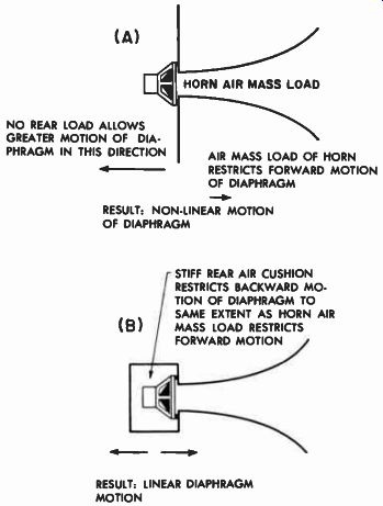
Fig. 10-10. One effect of the compression chamber is to produce linearity
of diaphragm motion by balancing horn air mass load with compression chamber
stiff ness. -------- (A) HORN AIR MASS LOAD NO REAR LOAD ALLOWS GREATER
MOTION OF DIA PHRAGM IN THIS DIRECTION AIR MASS LOAD OF HORN RESTRICTS
FORWARD MOTION OF DIAPHRAGM RESULT: NON-LINEAR MOTION OF DIAPHRAGM STIFF
REAR AIR CUSHION RESTRICTS BACKWARD MO TION OF DIAPHRAGM TO SAME EXTENT
AS HORN AIR (B) I MASS LOAD RESTRICTS FORWARD MOTION RESULT: LINEAR DIAPHRAGM
MOTION
Compression Also Improves Power Conversion
The second effect of this rear compression chamber is that it presents to the diaphragm a much better resistive load. Figure 10-11 shows the acoustic resistance and the acoustic reactance (inertance) characteristic of a horn operating in its pass band. Note that as the resistance factor begins to fall off the reactance factor rises. Although sound pressure may be developed across a reactance as well as across a resistance, no useful acoustic power will be developed in the reactance any more than useful electrical power can be developed in a choke coil. However, just as a choke coil, even though it doesn't absorb power, does produce a drop in voltage in a circuit, so the reactance element of the loudspeaker, though not developing power, does reduce the acoustic pressure available for useful power production across the resistive component of the horn characteristic.
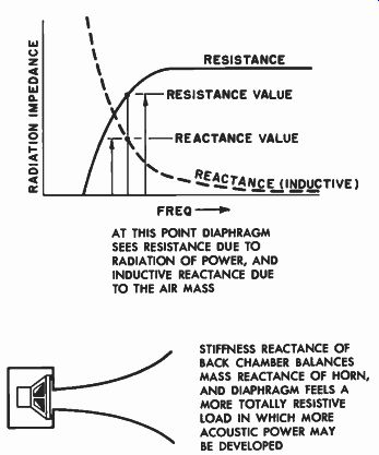
Fig. 10-11. Another effect of the compression chamber is to make the
load seen by the diaphragm more resistive by balancing the air mass
inertance with the chamber stiffness reactance. --------- FREQ. AT
THIS POINT DIAPHRAGM SEES RESISTANCE DUE TO RADIATION OF POWER, AND INDUCTIVE
REACTANCE DUE TO THE AIR MASS STIFFNESS REACTANCE OF BACK CHAMBER BALANCES
MASS REACTANCE OF HORN, AND DIAPHRAGM FEELS A MORE TOTALLY RESISTIVE LOAD
IN WHICH MORE ACOUSTIC POWER MAY BE DEVELOPED
If we can balance out this reactive element, more usable power will be obtained from the system. Fortunately, the acoustic stiffness in the air chamber also has reactance, but it is opposite in effect to the "mass" reactance of the air load. This is analogous to capacitive reactance, the effects of which are opposite to those produced by inductive reactance in electrical circuits. The stiffness and the mass balance each other out so that the overall transmission characteristic of the horn is more nearly resistive, with the result that more useful acoustic power may be developed by the driver-horn combination. For the information of the home constructor, the size of this rear air chamber should be equal to approximately three times the throat area of the horn times the length of a section of the horn in which the area doubles; thus volume = 3 X (throat area) X (horn length for area to double). With the parameters of horn throat, flare, and mouth size established, the woofer horn may be built. The project of building a compression driver horn-loaded system is an ambitious one and should be undertaken with the intention that it will be both acoustically correct and of the best workmanship possible. The success of a horn depends even more upon the quality of the workmanship than does that of a more simple enclosure-type system such as the bass-reflex cabinet. The importance of the manner in which these systems are constructed will be dealt with in detail in Section 14.
Advantages of Horn-Loaded Systems
The advantages of horn-loaded systems lie in the fact that it is possible in such systems to obtain relatively distortion-free output at the low frequencies because of the small motions of the diaphragm even when large amounts of acoustic power are realized. Secondly, the high efficiency of the horn-loaded system means, of course, that for a given power output the system does not have to be driven as hard electrically as the direct radiator baffle. This naturally results in more conservative use of amplifier power with consequently reduced amplifier distortion and better linearity of response during peak bursts of power.
Restrictions Imposed by Woofer Horn Enclosures
The disadvantages of home construction of the horn enclosure are the difficulty of construction and the fact that it cannot be adjusted after it is built to match it to its driver. Furthermore, in true horn systems of the compression type, separate speakers are necessary to cover the entire audible spectrum. The compression driver horn system itself is suitable only for woofer use because of its necessarily folded configuration, which prevents higher frequencies from negotiating the tortuous low frequency path. The fact that separate units are necessary for a horn installation is not necessarily a disadvantage, of course, for we know that such multi-speaker systems may be very fine systems.
The disadvantageous aspect is in the necessity of using such systems where one's budget will only permit starting with a single wide range speaker, or where one has decided to use a coaxial or triaxial assembly.
Because of the wide range features of these speakers, it is necessary for them to be mounted in enclosures from which direct radiation is possible.
Horns are Not Limited to Woofer Applications
Horn type baffles are, of course, not limited to woofer application.
In fact, they are perhaps more popular as high frequency baffles, and when so used may differ somewhat from the low frequency type. In basic design they are, however, identical; that is, they expand at some very definite rate determined by the theoretical cutoff required for the horn. Also, the mouth of the horn must bear some definite relationship to the lowest frequency to be transmitted. However, in one important aspect the high frequency horns do differ radically from the low frequency horns. This is in the variety of means used to control the diffusion of the high frequencies as they emerge from the horn so that they will be spread out over the room.
Every loudspeaker has a directional radiation characteristic, and the horn type is no exception. A round horn projector allows the low frequencies to spread out and beams the high frequencies, as does a cone speaker. However, with the horn several factors may be manipulated to obtain control over directivity. The manner in which these manipulations are made is discussed in Section 3, which deals specifically with tweeters and the horns that match them. It is seldom that the home constructor builds his own tweeter horn; the specialized driver unit invariably comes with its own horn attached. The horn is of the design recommended by that manufacturer to match the driver unit and the auxiliary equipment with which it is to work. However, one should not lose sight of the fact that the high frequency horn is just as true a baffle as the bass-reflex or any other kind of enclosure, but with the added features of control of the dispersion of the sound coming from the horn.