One of the most helpful developments in meter type measuring devices for testing electronic equipment is the incorporation of the vacuum-tube in the measuring instrument itself. The basic meter movement (ordinarily the moving-coil permanent-magnet meter) is connected into a vacuum-tube circuit in such a way as to indicate voltage, current, and resistance. The vacuum-tube voltmeter, abbreviated as VTVM, achieves its main advantage over the ordinary meter because it isolates the meter from the circuit under test; and, by utilizing the vacuum tube's capabilities as an amplifier or rectifier, greatly increases the sensitivity of the measuring system beyond that established by the meter itself.
Moreover, it extends the frequency range of the meter indicator far up into the hundreds of megacycles region. Finally, it minimizes the loading effect of the measuring device on the circuit under test.
Another advantage of the VTVM is that the input impedance is high and constant for all d-c voltage ranges; in contrast to the impedance of the ordinary multi-range voltmeter which varies according to the full-scale voltage range being used.
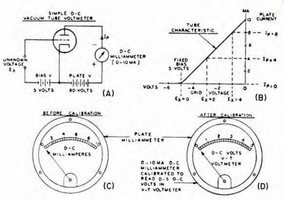
Fig. 9-1. The schematic and operation of a simple d-c, v-t voltmeter. The
appearance of the milliammeter scale before and after calibration illustrates
the manner in which the plate-current reading is interpreted in terms of unknown
voltage applied to the grid.
Most VTVM's have an input resistance of about 11 megohms; laboratory types go much higher. But even in the 11-megohm units this is equivalent to the input resistance of a 20,000 ohms-per-volt meter with a full-scale range of 550 v. However, it is on the low-voltage ranges that the advantage of the VTVM is most apparent. For example, a typical 20,000 ohms-per-volt meter has an input resistance of only 0.2 megohms on the 10-v scale; the constant 11-megohm resistance of the VTVM on this scale is 55 times as high. Therefore, we can say that for low voltage measurements where sensitivity is important, the VTVM is by far the most useful type of meter. At high voltages, 500 volts de and higher, the 20,000 ohms-per-volt instrument is just as useful as the vacuum-tube voltmeter. This must be said for the 100,000 ohms-per-volt meter too, which presents a meter resistance higher than the usual VTVM at voltages as low as 150 volts dc.
9-1. The Basic D-C VTVM
The direct-current VTVM is, in the main, an amplifying triode tube used in such a manner that the d-c voltage to be measured causes a change in its plate current. This current is indicated on a moving-coil meter. The voltage to be measured is applied to the control grid circuit of the vacuum tube; it offsets the operating bias and so changes the plate current to above or below the no-input-voltage value. When the plate current meter is suitably calibrated, its indications are interpretable directly in values of applied input d-c voltage.
The schematic in Fig. 9-1A symbolizes the basic arrangement. The conditions of operation are described by the grid voltage-plate current characteristic shown in Fig. 9-1B. Assume that a fixed negative bias just causes plate current cut-off with zero input voltage, the plate current meter indicates zero current. A positive voltage applied to the "input" terminals will offset some (or all) of the bias and cause plate current to flow. According to the characteristic shown, a positive input voltage of 2 volts applied to the grid will increase the plate current from 0 to 4 ma; a positive input voltage of 4 volts increases the plate current to 8 ma. A maximum input voltage of 5+ volts completely overcomes the operating bias and increases the plate current to 10 ma, the full scale reading of the plate current meter.
The relationship between input voltage and the plate current change enables calibration of the plate current meter in terms of the voltage applied to the input. Thus, instead of calibrating the plate meter in current from 0 to 10 ma, it can be calibrated in voltage from 0 to 5-volts full scale and becomes direct reading. Because the grid voltage-plate current characteristic is substantially linear ( within limits normally used) the meter scale is linear.
The limit of d-c voltage which may be applied to the vacuum-tube input circuit is determined by the operating negative grid bias, Because freedom from grid current is essential. However, it is readily evident that a meter of this type can neither be restricted in its measuring capabilities to a single range, nor to as low a value as 5 volts. The answers to both limitations are found in the use of a voltage divider across the grid circuit, as shown in Fig. 9-2.
By making the divider resistance very high, say 10 megohms or higher, the input impedance of the instrument is made high. When the taps along the divider are arranged in a suitable manner a wide range of d-c voltages can be measured, and the maximum voltage applied to the grid circuit remains 5 volts for full scale deflection on the meter for every range.
Each tap on the divider affords a certain voltage ratio between the voltage applied across the divider and the voltage applied to the tube.
Each tap along the divider represents a voltage range, to be used with its own scale on the meter or as a multiplying factor, as determined by the design of the instrument. In Fig. 9-2 the taps on the divider are arranged in decade steps of 1, 10, 100 and 1,000; these figures serve as multiplying factors. If the lowest full-scale range is 5 volts, the maximum voltage measurable with the device is 5,000 volts when the divider is set to the 1,000 position.
Referring to Fig. 9-2, it is interesting to note that, if the total divider resistance is 10 megohms, input impedance remains constant for the full range of the instrument, for all scales. Changing the voltage divider ratio by moving the range switch does not change the total resistance of the divider.
It might be well to comment that subsequent details explain the relationship between the resistance of the divider and the accessory (probe) equipments which are used with VTVMs.
9-2. Center Zero D-C VTVM
The arrangements in Figs. 9-1 and 9-2 require changing the input leads in order to accommodate negative voltages. One method of over
coming the need for changing polarity at the input circuit is the use of the center-zero voltmeter in a fundamental circuit, such as shown in Fig. 9-3. The tube is biased to operate half-way up the grid voltage-plate current curve. The d-c milliammeter (here located in the cathode circuit) accordingly reads in the center of the scale with no external voltage applied to the grid. The point on the meter scale is designated as zero voltage. The meter can now read positive or negative unknown voltages, as indicated on the scale shown in Fig. 9-3B, because the current can increase or decrease as determined by the input voltage.
Control R9 adjusts the plate voltage so that the meter reads zero with no external voltage. The grid is self-biased by cathode resistors R6 and R7. R6 helps stabilize the circuit by providing a suitable amount of degeneration, and control R7 is used to compensate for minor circuit variations. Selector switch SI and a voltage-divider network enable the voltmeter to operate over four different voltage ranges, and an a-c filter eliminates any a-c component in Ez.
The center-zero arrangement has the advantages of simple design and low cost, plus elimination of the need for a polarity switch to measure both positive and negative voltages.
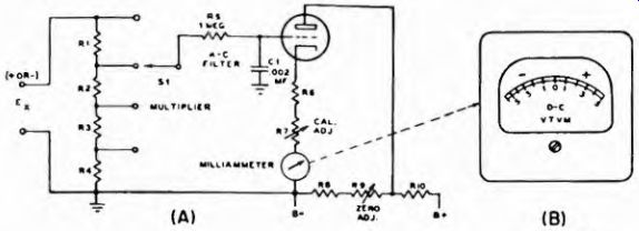
Fig. 9-3. (A) A center-zero instrument. (B) Typical scale calibration.
The circuitry used in commercial d-c VTVMs differs from these basic arrangements, even if the fundamental operating techniques do not. For instance, the modern day commercial instruments make use of two or more tubes in the metering circuit. In modern instruments these are bridge circuits, which are explained briefly in this section.
The reason for the more elaborate circuits is to develop the required stability in operation, especially the zero plate current settings, thus assuming maximum accuracy and achieving utmost sensitivity.
The vast majority of these instruments are a-c operated. Line voltage variations, differences in tube constants, changes in circuit elements, etc., will affect the zero setting, and the performance of the device, adversely unless steps are taken to use such circuits as minimize these effects.
9-3. The Two Tube Bridge Circuit
A circuit commonly used in the d-c VTVM is shown in Fig. 9-4A. The vacuum-tube system uses two tubes in a bridge circuit. Two arms of the bridge are the cathode resistors of the two tubes. The other two arms of the bridge contain the vacuum tubes themselves; one of these is the active tube, and the other tube, of identical characteristics, is used as a balancing tube in the other arm. The meter is placed between the cathodes, that is, between the tube ends of the series-connected cathode resistors.
The resistor R3 makes it possible to compensate for variations in the tubes. With no voltage input the plate current indication is zero, because there is the same difference of potential across each of the two cathode resistors. The plate resistances of the two tubes are alike, hence the entire circuit is in balance. When a voltage is applied to the input of the active tube, its plate resistance is changed and the bridge balance is upset. Current then flows through the meter because a difference of potential exists across the tube ends of cathode resistors. The resultant current flow through the meter can be interpreted in voltage input applied to the active tube. This is done by suitably calibrating the indicating meter in input volts.
Although the circuit in Fig. 9-4A does not show it, a voltage divider is found in the input circuit of the active tube. The resistor R4 is the series-multiplier resistor which makes the current meter suitable for use as a voltage meter; and, if made variable, affords a multiplicity of voltage ranges for the meter.
A variation of the two bridge circuit is shown in Fig. 9-4B. In this case the indicating meter is connected across the tube ends of the two plate load resistors R1 and R2. The potentiometer R3 serves the same purpose as before, to compensate for variations in the two tubes.
The resistors R4 and R5 are the two cathode bias resistors; R6 is the relatively high value common cathode resistor. These three cathode resistors contribute to the degeneration in the system.
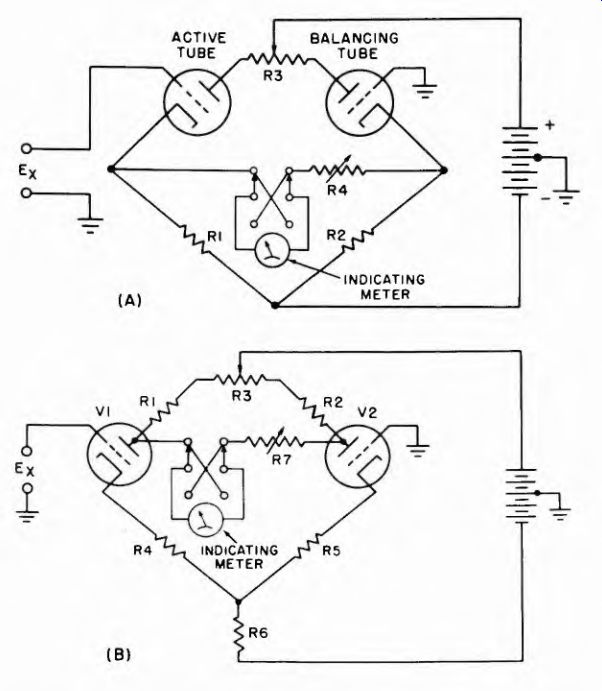
Fig. 9-4. (A) A two-tube v-t voltmeter in which the resistance arms are connected
in series with the cathodes providing degeneration as well as a bridge balance.
The meter is connected between the cathodes. (B) Two-tube push-pull bridge
d-c amplifier, with meter connected between the plates.
With no voltage input, the meter current is zero because no difference of potential exists between the ends of R1 and R2 where the meter is connected. The voltage to be measured is applied to V1 (the active tube), causing its cathode current and effective plate voltage (hence plate resistance) to change. The changed cathode current of V1 flows through the common cathode resistor R6, and causes the plate voltage of V2 to change in the opposite direction to the plate voltage change in V1. Hence the difference of potential across the terminals of the indicating current meter is twice (once for V1, and once for V2) what it would be if only one tube alone were used. This is the result of push-pull action.
The circuit is not sensitive to minor changes in tube electrode voltages stemming from the operating voltage sources, hence the zero indication is stable to a satisfactory degree.
Although described as d-c VTVMs, virtually all of these devices can measure d-c resistance and a-c voltage. As is shown elsewhere in this section, the a-c measuring VTVM uses the d-c amplifier system as part of the overall operating circuit - to measure the a-c voltage after it has been rectified.

Fig. 9-5 (A) A direct reading v-t ohmmeter circuit. The unknown resistance
is determined by measuring the voltage developed across it. A typical scale
is shown in Fig. 8-9. Fig 9-5 (B) Typical scale of a vacuum-tube ohmmeter using
the basic circuit shown in Fig. 8-8. This scale is used in the instrument shown
in Fig. 8-7 to cover the range from 0.1 ohm to 1,000 megohms.
9-4. Direct-Reading V-T Ohmmeter
By addition of the circuit shown in the left-hand portion of Fig. 9-5A almost any type of d-c VTVM is converted into an ohmmeter. The VTVM shown in the right-hand portion of the figure is a symbolized balanced circuit. It can just as readily be the bridge circuit ol Fig. 9-4.
Before R*, the unknown resistance, is placed in the circuit the lull-scale adjustment is made. In this condition the lull bias voltage of E1 is applied to the grid of the upper triode through one of the standard resistors, Rs. If Rz is now inserted in the circuit, Rs and Rz form a voltage divider across E1, and only the voltage drop across Rx is applied to the upper triode. The meter will then indicate something less than full scale, the amount being directly proportional to the decreased bias on the grid of the upper triode, and of course directly proportional to the resistance of Rz. The scale can then be calibrated in terms of the resistance of Rz. A typical scale calibrated in this manner is shown in Fig. 9-5B. Remember that before a reading is taken this ohmmeter is adjusted for full-scale without Rz in the circuit, thus signifying an infinite resistance.
9-5. The A-C VTVM
The VTVM used for measurement of a-c voltages involves a number of considerations in addition to those encountered in the d-c measuring device. Finished instruments allow the measurement of both a-c and d-c quantities, but the former entails rectification, whereas the latter does not. Thus, while a single VTVM may provide these two measuring capabilities, the a-c voltage measuring facility stems from a somewhat more complicated circuit arrangement.
The voltage of a rectified wave is proportional to the rms voltage of the a-c wave from which it is derived, hence magnitude is determinable after rectification. Whether amplification, which increases sensitivity, precedes or follows the rectifying action, is a function of design.
9-6. Series Diode Circuits
The simplest a-c VTVM circuit is that using a diode. The diode, of course, provides no amplification, its primary application being that of rectification. After conversion to a pulsating d-c voltage this a-c voltage causes the d-c meter to function and, by suitable calibration, to indicate the input a-c voltage.
The series type diode VTVM has the same circuit as the copper-oxide rectifier a-c meter discussed in Section 6. Like the copper-oxide rectifier, the diode characteristic tends to be non-linear, at low values of applied voltage and with a low value of load impedance. Figure 9-6 shows the diode characteristic with no load resistance (curve a), with medium load (curve b), and with high load (curve c). Curves b and c show that non-linearity may be almost eliminated by addition of a series resistance R of sufficiently high value. Unfortunately this lowers the overall sensitivity of the circuit, but is still a practical instrument.
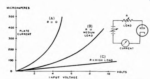
Fig. 9-6. Plate current-plate voltage characteristic of a diode under different
loads.
Figure 9-7 shows a series type diode circuit and the mode of operation on the diode plate voltage-plate current characteristic. The load resistor R has been made high enough to insure linear response, as for curve c in Fig. 9-6. The meter movement responds to the average rectified current, as explained in Section 6.
The sensitivity of this type of circuit is limited by the series resistor, R. Its frequency response is reasonably good up to the lower radio frequencies, where capacitive effects begin to interfere. At the higher frequencies the meter tends to follow peak voltages, due to stray capacitance. By adding a suitable capacitor across the diode load resistor (Fig. 9-8), the series-type circuit is made to respond to the peak value instead of to the average value. Note that the circuit then is practically the same as the detector of an a-m receiver. C must have sufficient capacitance to make its reactance low compared to the resistance of R at the frequency of the unknown voltage. The effect of this circuit on the rectified waveform is shown in Fig. 9-9.
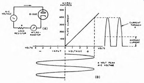
Fig. 9-7. The operation of a simple series type diode rectifier circuit.
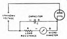
Fig. 9-8. A series type peak VTVM.
9-7. Shunt-Type Diode Circuits
When a-c voltages are to be measured in circuits which also contain direct current, the de must be kept out of the instrument. In the series type circuit just described there is a d-c return path between the measuring terminals, although d-c can be kept out of the voltmeter by means of a suitable series capacitor in the "hot" lead. Direct current can be kept out by use of the shunt-type circuit of Fig. 9-10. The a-c voltage to be measured is coupled through a suitable d-c blocking capacitor C to the plate of the diode, causing the tube to pass current on positive half-cycles. The tube conducts through the only available d-c path, that is, through the load resistor R and the meter M. The capacitor C keeps direct current from the voltage source from affecting the readings. This arrangement inherently responds to peak a-c voltage, because the charge time of the capacitor is longer than the time for a cycle of the a-c voltage.
VOLTS ACROSS
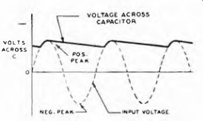
Fig. 9-9.
Effect of shunt capacitor C on rectified waveform.
9-8. The Triode-Type VTVM
In the diode-type circuits considered so far the lack of amplification limits the sensitivity of the instrument. Furthermore, because they must draw current from the circuit under test, the diode-type circuits have a definite loading effect.
Both of these limitations are overcome by the triode-type VTVM circuit. The amplifying ability of the triode circuit is used to provide greater overall sensitivity. Also, by operating the grid so that it draws no current, a high-impedance input circuit is provided. The voltage to be measured is applied between the grid and cathode, and (except for cathode followers ) the meter responds to the resulting plate current flow.
Three different modes of operation are possible, depending on the way the triode is biased, as illustrated in Fig. 9-11. When the operating point is at A the operation is called half-wave, because the negative half cycles are cut-off just as in the diode-type circuit. In fact, except for the...
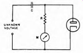
Fig. 9-10. Shunt type peak VTVM.
...amplification provided, the operation is equivalent to that of a diode with a relatively small load resistance. With bias at B full-wave operation is achieved, because there is plate-current flow on both the positive and negative half-cycles of the voltage to be measured. For so-called "peak operation" at C, plate current flows only on the tips of the positive peaks of the a-c voltage applied.
9-9. Half-Wave Square-Law VTVM
The basic circuit and operation of the half-wave square-law VTVM are shown in Fig. 9-12. As the designation half-wave implies, the operating grid bias is chosen close to cutoff so that the plate current is essentially zero when no signal is applied to the grid. When a signal is applied the plate current increases during the positive half of the cycle, as is shown at (b). On the negative half, however, no appreciable decrease in the plate current can take place. As a result of this rectification, the average value of the plate current increases when a signal is applied, and this increase can be taken as a measure of the voltage applied to the grid.
The outstanding characteristic of this type of VTVM is that the plate current is approximately proportional to the square of the voltage applied to the grid. This makes the calibration independent of the waveform, although there may still be some waveform error due to the phase of the harmonics present in the unknown voltage. Compensation
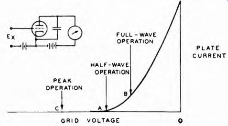
Fig. 9-11. The three modes of operation of the triode type VTVM.
for variations in waveform cannot be complete in the half-wave type of VTVM because the waveform of the negative hall cycles cannot directly affect the reading of the voltmeter.
9-10. Rectifier-Amplifier Type
Fundamentally all a c VTVM measurements depend upon rectification of the a-c voltage. As mentioned earlier, the advantage of rectifying the a-c voltage is that it permits the use of less expensive d e instruments. At the same time, the conversion of the unknown ac voltage into a d e voltage has the important advantage of enabling measurements to be made over a very wide range of frequency.
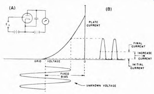
Fig. 9-12. The half-wave square-law VTVM.
In the VTVM's described previously, a basic rectifier stage is used with the d c meter inserted so as to measure the rectified plate current.
By adding a d e amplifier stage, as shown in Fig. 9 13, however, the performance can be greatly improved. The addition of the d c amplifier has the advantage of providing higher sensitivity, greater stability, a wider range, and, in certain instances, higher input impedance. These ad vantages can be realized because the separation of the functions of rectification and amplification make it possible to obtain the greatest efficiency in each.
The rectifier-amplifier type of VTVM is particularly well adapted for a probe type of input system. The probe is the movable extension of the measuring device, and contains the rectifying device. By joining the probe to the meter system through a flexible cable, ready access to the circuits to be measured is made available. Moreover, by bringing the rectifying device to the circuit under test, short leads between the circuit and the measuring device are possible, and very wide range of frequencies can be covered.
D-C METER
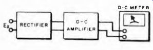
Fig. 9-13. Block diagram of the rectifier-amplifier type of v-t voltmeter.
Such rectifying means in probes are either vacuum tube diodes or germanium crystals. Since the leads from the rectifier to the metering circuit carry only d-c (and 60 hz a-c for heaters of vacuum tube diodes), this connecting cable is not critical in length. The illustrations in Fig.9-14 show a vacuum tube (A) and a crystal (B) as used in a-c measuring
VTVM probes.
9-11. Probes for D-C and R-F
A probe is a device which can be added to the input of an electronic voltmeter to facilitate the measurement of radio, intermediate, VHF and higher frequencies, and d-c high voltages. There are various types of probes, each designed for a specific purpose. In general, probes are designed either to increase the input resistance or to decrease the input capacitance of the voltmeter, hence to minimize circuit loading. In particular, d-c isolating probes minimize the effect of d-c measuring equipment leads in circuits carrying a-c or r-f signals.
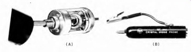
Fig. 9-14A. Vacuum tube diode probe.
Fig. 9-14B. Crystal type diode probe.
Fig. 9-15. Schematic diagram of a simple d-c probe.
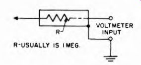
Figure 9-15 shows the circuit of a simple probe consisting of a resistor in
series with the cable input lead of the voltmeter. The resistance most commonly
used for this purpose is 1 megohm. If the d-c input resistance of the voltmeter
is 10 megohms, 10/11's of the voltage applied to the probe tip will appear
across the voltmeter terminals, and the voltmeter calibrated to read correctly
under these conditions. A direct connection to a voltmeter so calibrated yields
a reading 10 percent high.
The use of this resistor permits the probing of circuits without loading or detuning them. This is particularly important for the measurement of d-c bias in the grid circuit of an oscillator where loading is undesirable. A resistance of 1 to 5 megohms is enough to prevent resistively loading most circuits; the shunt capacitance of the resistor, usually of the order of 1 uuf, does not greatly detune or otherwise affect most circuits. The resistor also increases safety in making measurements, since it will effectively limit the current in case of bodily contact with lead or voltmeter terminals.
The range of a voltmeter may be extended to very high voltages by increasing the value of the probe resistance. A probe resistance of 991 megohms, for example, will multiply the range of a voltmeter having an input resistance of 10 megohms by a factor of 100, so that a 100-volt full-range scale will read up to 10,000 volts. (A 991-megohm resistor is mentioned because most meters are calibrated for use with a probe resistor of 1 megohm; this value must be added to the multiplier used.) The length of the probe must be increased so that it will accommodate a long 991-megohm resistor.
The longer the resistor and probe, the less chance is there that the probe will break down or arc over with 10,000 volts across it. A barrier is usually provided on these probes to prevent the user from handling the tip and making contact with the high voltage being measured (see Fig. 9-16) . These probes drop the voltage to a sale point at the VTVM terminals and limit the current to a sale value. For instance, a 1,000- megohm probe resistor limits the current from a 30,000-volt source to 30 microamperes. An additional precaution used in some probes is the inclusion of a grounded shield in the handle extending up inside the barrier. In case of an arc-over the spark will jump to the grounded shield rather than to the user's hand.
Precision Apparatus Co.
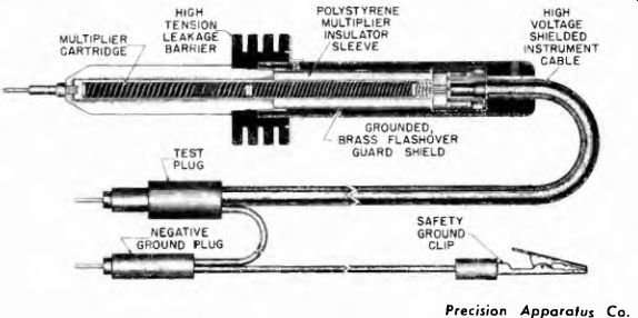
Fig. 9-16. Cross section of a multiplier type d-c probe, showing the long
ribbon-wound resistor, the guard shield, and the barrier. Note that the resistor
extends almost the full length of the probe.
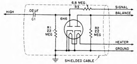
Fig. 9-17. Circuit diagram of diode-rectifier probe used for a-c and r-f measurements.
9-12. A-C Probes and R-F Probes
Figure 9-17 is the circuit diagram of a typical diode-rectifier probe used for a-c and r-f measurements. The input impedance is derived from the combination of shunt and series resistors and capacitors shown in the signal-diode circuit. The second diode is used to balance the contact voltage of the first.
Suitable input terminals, one of which is usually grounded, are provided on the probe; jacks, clip leads, or short wires soldered to the circuit under test, are used for connecting purposes.
Since a probe permits the use of very short connecting leads, its widest application is with high-frequency voltmeters. Since early VTVM's were single tube affairs in which rectification and d-c amplification or meter coupling were accomplished in a single tube, .and since early tubes were large and awkward, the first probes were cumbersome.
Gradual development has evolved smaller and smaller probes mounted on more and more flexible cables.
Figure 9-18 shows a well designed probe capable of measuring r-f voltages to about 1,000 mhz. The tube used in this probe was specially designed to reduce stray capacitance, stray inductance, and other error introducing factors. At frequencies above a few hundred kilocycles, long ...
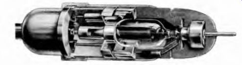
Fig. 9-18. Cross-sectional view of a Hewlett-Packard r-f and high-frequency
probe used for measurements up to 1,000 mhz.
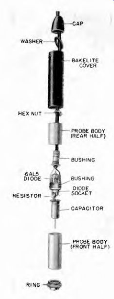
Fig. 9-19. Disassembled RCA duo diode probe used for measurements from audio
frequencies up to about 250 mhz.
... connecting leads introduce such errors and increase the circuit loading.
Therefore the probe shown in Fig. 9 18 is not only interesting from a design standpoint, but also is necessary for maximum accuracy at high frequencies.
The probe shown in the cutaway view in Fig. 9-19 is the RCA model WG-275. Audio-frequency voltages up to 100 volts rms can be measured with this unit. Its upper frequency limit is above 250 mhz.
9-13. Crystal Probes
A convenient type of rectifier found in probes used with VTVMs is the germanium crystal "crystal probe." A typical circuit is shown in Fig. 9-20. It is intended for peak voltage measurements on sine-waveform voltages. A peak-to-peak measuring probe is shown schematically in Fig 9-21 Although crystal devices are used at frequencies in the microwave region, the general run of crystal probes are intended for frequencies up to about 250 mhz. Unlike the tube diode, the crystal probe requires no heater excitation, hence the probe carries only the rectified (pulsating d-c) signal, and the lead length is not too critical.
CONSTANTS DIFFER IN DIFFERENT PROBES TO SUIT RECOMMENDED FREQUENCY RANGE -O OUTPUT NEGATIVE POLARITY FOR POSITIVE ALTERNATION OF INPUT
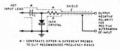
Fig. 9-20. Peak -reading r-f probe for VTVM.
Crystal probes recommended for VTVM use are basically peak rectifiers. The lowest frequency of operation is determined by the time constant of the probe circuit itself. The frequency expressed as time interval (i - 1/f) should be at least 1/10 of the time constant of the probe to afford peak rectification.
When only the modulation component of a modulated r f carrier is to be measured, it is necessary that the crystal probe meet the following requirements: The time constant of the probe has to be at least equal to 10 times the modulation frequency; also the probe time constant should be 1/10 or less of the carrier frequency. Only when these two requirements are met will the probe give the desired results.
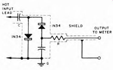
Fig. 9-21. Simple peak-to-peak r-f probe for VTVM.
The modulation and carrier frequencies have to have a ratio of 1:100 or better to permit peak detection. Whenever the time constant of a crystal probe is calculated, the shunt capacity of the leads and the input impedance of the meter (input resistance and capacity) have to be taken under consideration. A crystal probe should be considered as a variable load on the circuit where it is used for measurement. The actual impedance of the probe varies with frequency. That is mainly due to the reactance of the blocking capacitor C.
The maximum voltage which can be applied to crystal probes is again determined by the reactance of the blocking capacitor at the frequency of operation and the inverse peak voltage rating of the crystal.
It is obvious that the blocking capacitor and the crystal act as a voltage divider which has a variable ratio depending upon the frequency of operation. In no case should the peak voltage appearing across the crystal be greater than the maximum peak inverse voltage of the crystal used in the probe.
Usually a crystal probe for a VTVM contains a series resistor in the probe-to-VTVM lead. The function of this resistor is twofold. First, this resistor provides isolation between the probe and the meter and, secondly, permits adjustment so that the meter reading is correlated to the voltage applied across the probe.
Just what this voltage is for different crystal probes is stated by the manufacturer. As a generalization, safe maximums should not exceed 50 volts, although some crystal probes have been rated as high as 100 volts.
9-14. Frequency Correction Curves
While the useful frequency range of VTVM diode probe heads is broad, the accuracy of indications over the frequency range of these instruments is not uniform. Accordingly, some test equipment manufacturers provide frequency correction curves that correlate frequency and voltage reading. In this way, the actual voltage present at the probe tip can be determined. Examples of these correction curves appear in Fig. 9-22 and Fig. 9-23. Complete data of this kind accompany instruments which require them.
9-15. Input-Resistance Correction Curves
The input resistance of probe heads does not remain constant over a wide band of frequencies; hence it is important to know what Courtesy of Sylvania Fig, 9-22. Graph of voltmeter reading error versus frequency of measured voltage for various voltage values measured on a v-t voltmeter using a diode-rectifier probe with a 5647 tube-correction factors must be applied. This information is furnished with instruments which are designed to operate over a frequency band in which the change in input resistance is substantial. An example of an input-resistance correction curve appears in Fig. 9-24. Note that the input resistance remains constant over a range from about 60 hz to 500 khz, then begins to fall. At 100 me the input resistance of the probe head falls to 700 ohms. This change in input resistance must be taken into account if correct measurements are to be obtained.
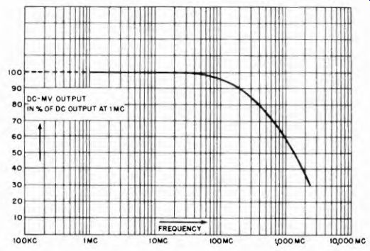
Fig. 9-23. Frequency correction curve for the Millivac Instruments model MV-18B
using crystal probes.
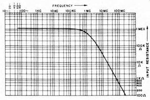
Fig. 9-24. Input resistance vs frequency curve for RCA type WV75A.