(cont. from part 1)
10-20. Voltage Measurements in Electronic Equipment
Two kinds of voltage measurements may be called for as a part of the servicing routine for electronic equipment. One of these is the operating voltage, ac or de as the case may be, and the other is the signal voltage which may be present in the system. The application of meters to each is discussed here.
Operating Voltages. The operating voltages are of two kinds, ac and dc. D-c operating voltages exist at the cathode, control grids, screen grids, and plates of the ordinary run of vacuum tubes. If the equipment is operated from d-c primary sources, the heater or filaments of the tubes also will be subject to d-c operating voltages; if the equipment is operated from a-c primary power, the heaters or filaments are subject to a-c operating voltages.
In the event of a-c primary power operation and rectifier power supplies, a-c operating voltages will be present across the input to the power supply, across the secondary winding or windings of the power transformer, and therefore across the rectifiers, whether vacuum tube or of metallic type.
In the case of battery operated mobile equipment which uses vibrator type power supplies or dynamotors, d-c operating voltages may be present across the primary and secondary contacts of the vibrator, or only across the primary, depending on whether it is a synchronous or a nonsynchronous type. In the case of the latter, a-c usually will be present across the secondary of the transformer and across the rectifier tube. In the case of a dynamotor, d-c will be present across the motor and across the generator windings.
Operating voltages are measured between the terminals to which they are applied, whatever may be the reference point, common to all or some, of the voltages. Generally ground is this reference point. Usually it is at the same potential as the chassis or case, and is the B- point in the system. On occasion, the chassis is at a higher potential than ground, but is the B- terminal nevertheless. In almost all cases it is customary to reference operating voltages relative to ground, by which is meant B-.
Reference voltage information appears in service literature in one or more of three general forms. One is the chart form stating the operating voltages extent at the different tube electrode pins on the tube sockets, as shown in Fig. 10-32A; in another it appears alongside the tube electrode symbols on the schematic, shown in partial form in Fig. 10-32B; and, in the third form, it appears adjacent to the socket terminals for the different tube electrodes in underside chassis views, as shown in Fig. 10-32C. In all instances they bear a tolerance of plus or minus 10-15 percent.
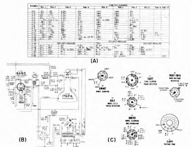
Fig. 10-32 (A) Voltage chart. (A) Emerson.
Fig. 10-32 (B) Partial schematic showing operating voltages next to tube electrode " symbols. (B) RCA.
Fig. 10-32 (C) Voltage labels adjacent to socket terminals or underside of chassis. (C) Stewart Warner.
Sometimes the voltage values are given in pairs in these chassis bottom views; one set of figures applies to measurements made with 20,000 ohms-per-volt voltmeters while the other set applies to measurements made with VTVMs. Naturally these are suitably labeled.
A-c operating voltages appear in the chart form and in the bottom views in the same manner as the d-c voltages. On schematic diagrams they usually are marked next to the appropriate winding of the power transformer. Sometimes a d-c operating voltage is labeled on a voltage bus which feeds a number of circuit points. If no important voltage drops intervene, the voltages at these circuit points are all equal to that at the bus. In resistance-coupled amplifiers, the voltage drops in load and coupling resistors must be taken into account. The meter must then be appropriate to the series resistance. Signal voltages in electronic equipment are essentially alternating in character. Depending on the kind of equipment, they are modulated and unmodulated sine waveforms and other complex waveform voltages.
Influence of Waveform on Voltage. Some tube electrodes are simultaneously subject to d-c and a-c voltages; sometimes the complex
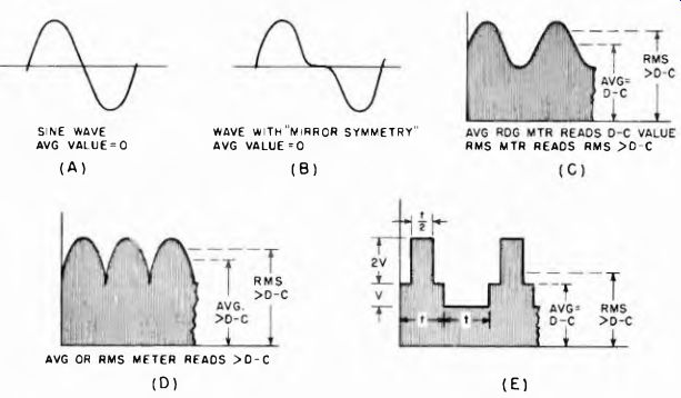
Fig. 10-33. How combinations of a-c and d-c voltages affect meter readings.
A d-c voltage reading with a permanent-magnet moving-coil meter is affected by the presence of an added a-c component only if the latter has an average value different from zero, as in (D). Note, in (E), that an a-c component wave does not have to be symmetrical to have an average value of zero.
a-c voltage is symmetrical and in some cases unsymmetrical. An isolating capacitor keeps de out of the meter for a-c measurement. A-c voltage can be kept from the meter during d-c measurements in some cases by use of a low-resistance series choke in the meter lead. Whether the a-c voltage affects the d-c voltage measurement is determined by the waveform of the a-c voltage and the kind of measuring equipment.
A wave is said to be symmetrical if the shape of the waveform of one polarity is a duplicate of the waveform of the other polarity. For example, a sine wave (Fig. 10-33 (A)) is symmetrical. A special kind of symmetry is that in which the values of one polarity are repeated in reverse order by the other polarity, as shown in Fig. 10-33 (B). This is known as ''mirror symmetry."
We are concerned here with measurement of voltages containing both an a-c and a d-c component. For these, the important thing about a symmetrical waveform a-c component is the fact that its average value is zero. Thus an average-reading d-c meter, such as the moving-coil permanent-magnet type, reads the same d-c voltage whether or not the symmetrical a-c component is added to it. If the meter movement is of the dynamometer or thermocouple type, operating on the square-law principle, it reads the rms value of the total voltage (a-c plus d-c) as shown in Fig. 10-33 (C). In this case, a true indication of the d-c voltage alone could only be obtained if the a-c component could be somehow removed or separated from the d-c component.
If the a-c component wave is unsymmetrical, the average value of the composite voltage (a-c plus d-c) is different than the d-c value.
Then both average-reading and square-law instrument indications are affected by the presence of the a-c component with the d-c voltage.
It should be noted that an a-c component wave does not have to be symmetrical to have an average value of zero, as exemplified by the unsymmetrical zero-average a-c component of Fig. 10-33 (E). Of course, such waves are rarely encountered.
As has been stated in Section 9, some a-c meters are intended for the measurement of sine waveform voltages, whereas others are capable of indicating the level, as peak or peak-to-peak, of complex unsymmetrical waveforms. Moreover, the measurement of a-c signal voltages also is influenced by the impedance of the source and the impedance of the voltmeter at the frequencies represented by the a-c signal, and also by the frequency of the signal and the range ol frequencies over which the meter functions. This may introduce the need for supplementary equipment such as probes.
A guide of this type cannot contain a discussion of the operational theory of all of the circuitry to which meter type measuring devices can be applied. It must presuppose that the user of the equipment has guidance of some sort in the behavior of the equipment under test, and is concerned with the methods involved in applying the different kinds of meter type measuring devices. These are discussed herein.
10-21. Suitability of the Voltmeter
The suitability of the voltmeter for making measurements of voltage is determined by a number of factors. These are:
a. The kind of voltage to be measured; whether it is ac or dc. This establishes whether the device must be a-c indicating or d-c indicating.
b. The amplitude of the voltage to be measured. This determines the required voltage range of the voltmeter.
c. The resistance of the circuit across which the voltage is to be measured. This determines the required input resistance of the voltmeter so as to minimize loading of the measured circuit and influencing the performance of the system whose voltage output is being determined.
This is important in both d-c and a-c measurements. The 20,000 ohms- per-volt voltmeter has become standard as a d-c voltage measuring unit among many manufacturers of electronic equipment, although an equal number favor VTVM. The recently announced 100,000 ohms-per-volt voltmeter will, no doubt, gain popularity.
d. The waveform of the a-c voltage. This is important mainly in the self-generating systems in electronic equipment which produce complex nonsymmetrical waveform voltages which must be measured.
These, and even the symmetrical a-c signal voltages, must be measured in peak-to-peak values; this requires particular design of the measuring device. Moreover, the duration of the pulse in a waveform of the non-symmetrical variety has a bearing on the type of voltmeter that is suitable for such tests.
Unless otherwise stated, all a-c measuring voltmeters are intended for sine-waveform voltages. Although the scale calibration may read in rms and peak, or even peak-to-peak values, they are not suitable for complex a-c waveforms unless specifically identified as such.
e. The frequency range of the voltages to be measured. This determines the frequency range of the voltmeter. As stated earlier, the conventional a-c voltmeter which does not use a rectifier is intended for power frequencies. Those with metallic rectifiers are intended for operation up to about 70 khz. Those with crystal or tube diode rectifiers will cover the previously mentioned range and go far above it. However, it is important to note that two factors influence the usable frequency range of even VTVMs. These are (1) the impedance of the source of voltage relative to the impedance of the meter (the higher the impedance of the voltage source relative to the impedance of the meter, the lower the frequency range of the meter), and (2) the voltage range of the meter. The constants of the device are not the same on all ranges.
Reference voltage information frequently states the kind of instrument needed. In the case of television receiver signal voltage waveforms, as well as the voltage waveforms in other kinds of equipment, it has become customary to assume that oscilloscopes will be used to indicate amplitude as well as waveform. The voltmeter cannot be expected to give the same information as the scope, but it must be realized that the peak, or peak-to-peak reading VTVM, can be used for the measurement of voltage amplitudes of these special waveshapes. The reference voltage figures can be gathered from the waveform patterns that appear in tv or other service literature, since the peak-to-peak amplitude values always accompany the waveform illustration.
When the reference voltage information gives the amplitude of an a-c voltage in rms values, any form of a-c voltage calibration is satisfactory, because conversion from one to other is simple. Since a sine waveform voltage input is assumed, the conversion from peak or peak-to-peak to rms values is easy. Peak-to-peak/2.83 = rms.
Peak x .707 = rms. RMS x 1.41 = peak. RMS x 2.83 = peak-to-peak.
But when the waveshape is complex and the peak value must be determined, then the meter must be of the type which is capable of measuring voltage waveforms of this kind; if it is not, then the conversion of rms to peak or peak-to-peak values as stated above will not be correct.
10-22. Kinds of Voltmeters Used in Vacuum Tube Circuits
The following might be considered to be generalizations concerning the kinds of voltmeters which are suitable for d-c and a-c operating voltage measurements in different vacuum tube circuits.
a. In control grid circuits of amplifiers, limiters, mixers, and detectors the 20,000 ohms-per volt meter alone or as a part of a VOM is usable without any difficulty, although the VTVM will result in less circuit loading. When the voltage is low and the circuit resistance is high, the VTVM is preferred, and might be the only useful device. This is definitely so in some first a-f stages in receivers with 10 megohm grid resistors.
b. In oscillator circuits, the VTVM is preferred for measurement in the grid circuits, and it, or the 20,000 ohms-per-volt instrument, will suffice in the screen and plate circuits.
c. In the plate and screen circuits of amplifiers, either the 20,000 ohms per volt device or the VTVM can be used.
d. All operating voltages in a-c heater circuits, low resistance cathode circuits, power line circuits, and plate circuits of power supply rectifiers, are measurable with the usual run of a-c voltmeters in VOMs and VTVMs.
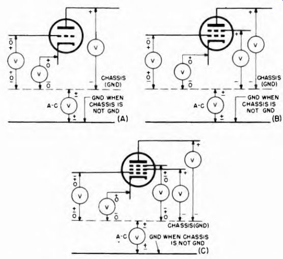
Fig. 10-34. Polarities of various vacuum tube circuit points with respect
to chassis ground.
e. The load circuits of diode rectifiers used as avc and age sources will accommodate either 20,000 ohms-per-volt voltmeters or VTVMs. If the output d-c voltage is low and the load resistance is high, the VTVM will be found to perform better than the conventional voltmeter.
f. The load circuits of ratio detectors and discriminators will accommodate either 20,000 ohms-per-volt voltmeters or VTVMs.
10-23. Polarities of Operating Voltages
As far as operating voltages are concerned, Figs. 10-31A, B, and C illustrate the general order ol polarities relative to the B- point, which is assumed to be the chassis of the receiver. Triode, tetrode, and pentode types of multi-electrode tubes are considered, but the manner in which the tube is used is unimportant. Every possible condition may not be covered in these illustrations, but it is felt that the vast majority of cases are included.
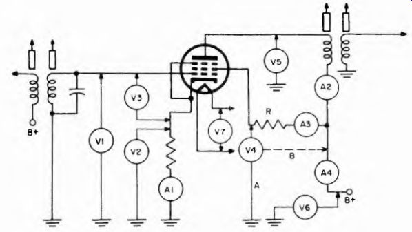
Fig. 10-35. A pentode transformer-coupled amplifier stage, showing locations
for current and voltage readings. In a triode stage, readings are the same
except that those connected with the screen grid and suppressor grid circuits
are eliminated.
The kinds of circuit components which may be used in the grid, plate and cathode circuits of these tube structures are important relative to the operating-voltage only to the extent that they determine the resistance of the circuit across which the voltage is to be measured. It can just as readily be a resistive as an inductive load (transformer or coil) without modifying the polarity references, shown adjacent to the tube electrode symbols in Fig. 10-38, or the polarities shown at the chassis.
10-24. D-C and A-C Operating Voltage Measurement in Amplifiers
The possible points of measurement of d-c and a-c operating voltages in a transformer coupled amplifier are shown in Fig. 10-35. For the sake
-------------
V1 Indicates d-c control grid-ground (grid-bias) voltage
V2 Indicates d-c cathode-ground (cathode-bias) voltage
V3 Indicates d-c control grid-cathode voltage
V4a Indicates d-c screen-grid voltage
V4b Indicates d-c voltage drop across screen resistor
V5 Indicates d-c plate voltage
V6 Indicates d-c B+ supply voltage
V7 Indicates a-c heater voltage
A1* Indicates d-c cathode (total plate) current
A2* Indicates d-c plate current
A3* Indicates d-c screen current
A4* indicates d-c plate and screen current
* Current measurements are not too common; usually limited to very high current circuits.
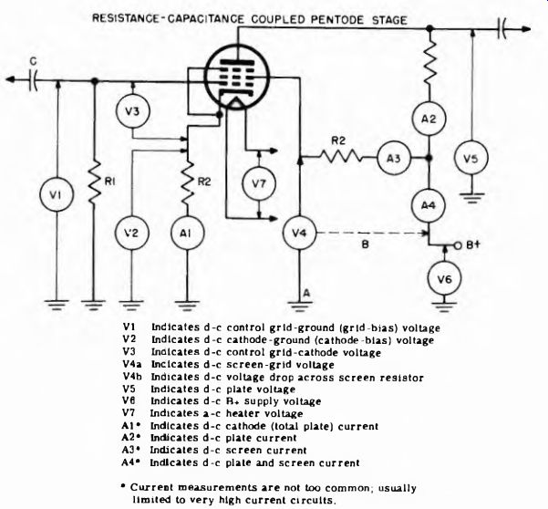
Fig. 10-36. A pentode resistance-capacitance-coupled amplifier stage and typical
meter reading locations. For a triode in the same circuit, simply eliminate
the screen grid and suppressor circuits.
---------------------
... of simplification, decoupling resistors and bypass capacitors have been omitted. The presence of these circuit components does not affect the points of operating voltage measurement, although their manner of performance could affect the presence of the voltage, and even its magnitude.
The nature of each indication in this group is stated beneath the respective schematics in Figs. 10-35 through 10-38. The circuits are shown with pentodes in each case. Triode circuits are handled similarly, except that there are no screen grid or suppressor circuits.
Although it is recognized that tube current measurements are not too common in maintenance operations, being more frequently carried out in school or design laboratory activities, they are shown to illustrate the points where current meters can be connected. Interestingly enough, the use of current meters is becoming more popular in high-quality audio amplifier systems of the push-pull type, as symbolized in Fig. 10-37.
---------------------
V1a-V1b Indicates d-c control grid-ground voltage across each hall ior each tube
V2 Indicates d-c cathode-ground (cathode bias) voltage V3a-V3b
Indicates d-c control grid-cathode bias for each tube V4a-V4b Indicates d-c respective screen voltages V5a-V5b Indicates d-c respective plate voltages. Dotted line connections indicate d-c voltage drop across each half of primary winding.
V6 Indicates d-c B+ supply voltage Al Indicates d-c total cathode current A2a-A2b Indicates d-c individual cathode currents A3a-A3b Indicates d-c individual screen currents A4a-A4b Indicates d-c individual plate currents A5 Indicates d-c total screen and plate currents
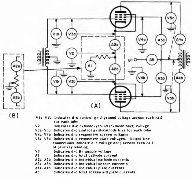
Fig. 10-37. Push-pull transformer coupled stage, showing possible d-c operating
voltage and current readings. For triodes, eliminate screen grid and suppressor
grid circuits.
---------------------------
Individual current meters are located in the cathode circuits, or at least jacks are provided for them so that the cathode currents in the individual tubes which form the push-pull stages can be adjusted for proper balance. The arrangement used for cathode bias, to omit this conveniently, is shown in the respective dotted line enclosures. By varying the slider on the potentiometer type of cathode bias resistor, variations in the tube currents can be compensated for.
The phase inverter system shown in Fig. 10-38 is but one example of a great many. The manner of obtaining the phase inverted signal from the single-ended input tube differs in many systems; but even so this circuit illustrates the numerous points where d-c and a-c operating voltages are applied so as to form a system which will result in a balanced input to the output stage and a similar output. It is interesting to note the organization of the phase-inverter tube operating voltages, especially the use of the grid resistor R4 system of one output tube as the grid resistor for the phase-inverter tube.
Grid Voltage Measurements. Amplifier circuits which use blocking capacitors in the control grid circuits raise an interesting point relative to de bias voltage measurements in these circuits. Examples of this are the voltmeter readings V and V3 in Fig. 10-36, and V3 and V6 in Fig. 10-38. Excessive leakage in the blocking capacitors in control grid circuits is not uncommon. When this occurs the preceding tube plate voltage causes current to flow though the grid resistor of the tube in the succeeding stage. Thus, in Fig. 10-36, such action would result in a current flow through R1 and develop a voltage drop across it. This would be indicated on V1. Under normal no-signal conditions this meter would indicate zero voltage.
In the event of leakage in the blocking capacitor C, the normal bias developed by the cathode resistor R2 is partially (or completely) over come by the current through Rl, and the V3 indication is less than the V2 indication. Normally these are alike, except possibly for what slight difference might be occasioned by the presence of R1 (if it is very high) in the voltage measuring circuit.
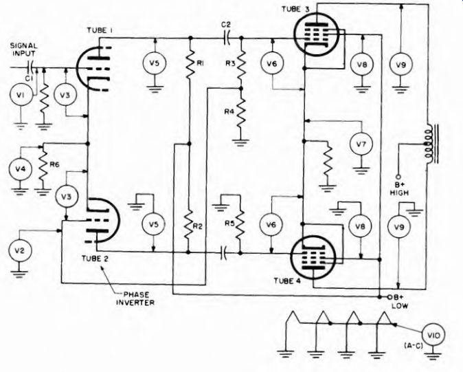
Fig. 10-38. Possible d-c operating voltage measurements in a typical phase
inverter push-pull amplifier system.
----------------
V1 Indicates the maximum d-c control voltage generated In the AVC diode for a given signal and supplied to an i-f tube
V2 Indicates a reduced d-c control voltage supplied to the r-f stage and to the first i-f stage, and available at a point on the AVC diode load resistor
V3-V4 Indicates the AVC voltage supplied to the r-f tube
V5 Indicates the AVC voltage supplied to the first i-f tube
V6 Indicates the fixed minimum bias generated in the cathode circuit of that i-f stage
V7 indicates the total bias applied to between grid and cathode of the t-f tube - the sum of the AVC bias and the fixed minimum bias
V8, V9, V10
The same as V5, V6 and respectively except it is the higher AVC bias tor the second l-f tube
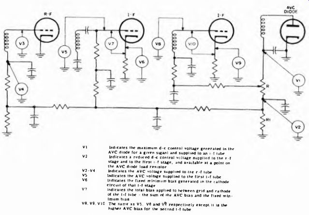
Fig. 10-39. Examples of d-c control voltage measurements in radio receiver.
-------------------
A leak between plate and grid winding in a transformer-coupled system, such as in Fig. 10 35, can also be harmful. It can modify the control grid-cathode voltage shown on V3 or it can overcome it completely. In the last event the control grid would be positive and the indication on VI would be a positive voltage representing the voltage drop developed across the secondary winding of the transformer.
The significance of these few circuit examples does not lie in the specific procedure, but rather in the philosophy that the operating requirements of the tube dictate the application of operating voltages.
Although we have remarked that operating voltages are relative to a B- reference point, we have given several examples to show a departure from this. These are the control grid-cathode voltages, which are important because they show that the control grid circuit voltage can be zero rather than negative, depending on the reference point.
10-25. D-C Voltage Measurements in AVC Circuits
The measurement of d-c voltages in control circuits warrants special comment. Inasmuch as the normal d-c and a-c operating voltages are measured without signal input, it is important to note that control voltages are absent unless a signal is applied to the system.
The usual function of a control circuit is to furnish an automatically generated and varying control grid bias which varies the behavior of the amplifier tubes. Sometimes this control voltage is the only bias ap
plied to a tube, as for example in the r-f stage shown in Fig. 10-39. At other times it is an added bias applied to a fixed minimum generated in the cathode circuit, as shown in the i-f stages in the same illustration.
The types of control circuits used in radio receivers vary in specific organization, but do bear great resemblance to one another.
The amount of bias voltage generated in the avc diode (or triode as the case may be) is a function of the applied signal. This makes possible using the avc voltage as an indicator of the condition of resonance when aligning a receiver, fn some circuits, called "delayed avc" circuits, avc bias is zero unless the received signal voltage exceeds a predetermined minimum value.
10-26. D-C Voltage Measurements in Oscillators
Measurements of d-c operating voltages in oscillators used in radio, tv, and other equipment depend on the function of the oscillator. If it is a heterodyning oscillator, the d-c voltage measurements generally are two in number: the rectified grid voltage, generated while the tube is oscillating, and the plate voltage. These are shown in Figs. 10-40 (A) and 10-40 (B) for two common kinds of oscillators. These need not be triodes, they can be other tube types.
As a rule, the plate voltage measurement (V2) in both illustrations is less important than VI. If the latter shows the control grid to be negative relative to ground, the system is oscillating; and if the magnitude of the voltage measured or VI conforms with the reference information, the V2 measurement is unnecessary. The magnitude of the rectified grid voltage is proportional to the amplitude of oscillations. Grid voltage must always be measured with a high-impedance meter, preferably a VTVM, to minimize loading on the high-impedance grid circuit.
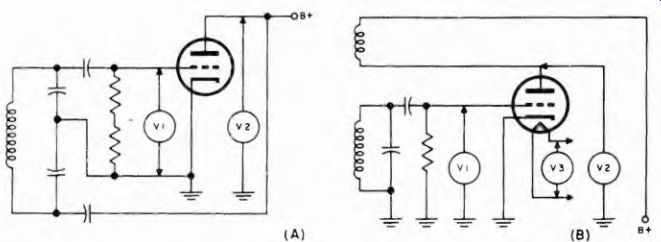
Fig. 10-40 (A) Examples of d-c operating voltages in Colpitis oscillator.
Fig. 10-40 (B) Examples of de and a-c operating voltages in tickler feedback oscillator.
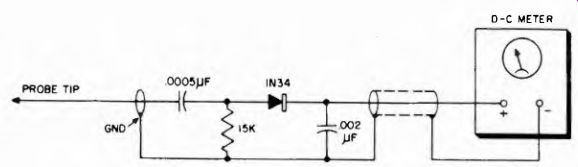
Fig. 10-41. Typical circuit for r-f probe, which is sensitive to the field
of an oscillator without contacting the oscillator circuit.
Although only two examples of heterodyning oscillators are shown here, all other types are treated in a similar manner. The control grid will be negative relative to ground when the system is oscillating. The amount of voltage present across the grid leak will vary with the conditions in the circuit, and with the frequency setting if it is a variable frequency oscillator. Practical values can be as low as a few volts to as high as 20 or 30 volts.
-----------
V1 Indicates mixer grid bias from A VC system
V2 Indicates mixer plate voltage
V3 Indicates oscillator grid voltage
V4 Indicates oscillator plate (and screen grid) voltage
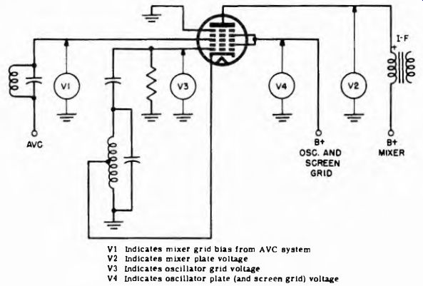
Fig. 10-42. Typical converter circuit with voltage-checking points.
---------------------
Measurement of the plate voltage or grid voltage may cause a change in output frequency. This is not harmful because it exists only while the meter is connected across the circuit. However, if the loading effect of the meter is enough to stop oscillation the check is worthless.
The field surrounding an oscillating system affords a simple means for determining if an oscillator is functioning. Detection of this field by probe pickup without contact permits the use of a low input resistance meter without undue loading. The circuit is shown in Fig. 10-41.
An ordinary crystal probe is connected to a meter which is set to a low d-c voltage range. The probe tip is held near the elements ol the oscillating circuit, near the tube grid terminal at the bottom of the socket, or at its cathode, or near the tank coil, but not in contact with these points.
If the circuit is oscillating, the crystal in the probe will rectify the field energy and a voltage will be indicated on the meter.
10-27. D-C Voltage Measurement in Converters
Measurement of d-c and a-c operating voltages in receiver converters presents no peculiar problems. They are made in the same way as shown in Sections 10-23 through 10-28. Converters are single-envelope combinations of mixers and oscillators, hence the possible points of operating voltage measurement in the multi-electrode tubes used for this function represent the composite of the section used as the mixer and the section used as the oscillator. Since only the cathode is common to both sections, a single cathode-ground voltage measurement will suffice.
---------------------
V1 Indicates cathode bias active for the oscillator and mixer sections
V2 Indicates oscillator grid (pin 4) voltage
V3 Indicates oscillator plate (pin 3) voltage
V4 Indicates mixer screen grid voltage
V5 Indicates mixer plate voltage
V6 Indicates mixer control grid-ground voltage
V7 Indicates mixer control grid-cathode bias voltage
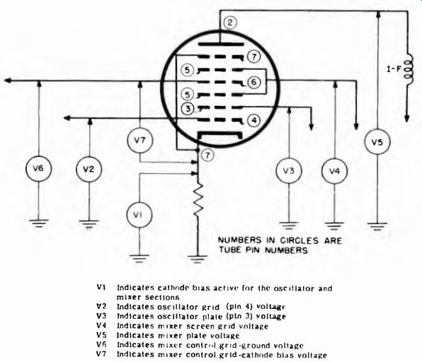
Fig. 10-43. Another type of converter circuit.
--------------------
A typical converter circuit is shown in Fig. 10-42. It is a 6SA7 pentagrid tube. One section is grids 1 and 2 acting in conjunction with the cathode form the oscillator electrodes. Grids 3, 4 and 5 and the plate, acting with the cathode, form the mixer section. Grid 4 is the screen grid and grid 5 is the suppressor grid. The connections between grids 2 and 4 are made internally.
As far as d-c operating voltages are concerned, four electrodes receive d-c voltages. The oscillator grid 1, the oscillator plate 2 (and the screen grid 4), the mixer grid 3, and the plate. These are labeled in Fig. 10-42.
Another version of a converter, the 7A8, uses six grids, a cathode, suppressor grid, and plate. Its name is octode converter, and it is shown in Fig. 10-43.
---------------
V1 Indicates a-c line voltage Input V2 Indicates voltage applied to each rectifier plate V3 Indicates rectifier heater voltage V4(a) Indicates d-c voltage at input of filter V4(b) Indicates d-c voltage at midpoint of filter V4(c) Indicates d-c voltage at output of filter V4(d) Indicates d-c voltage at point on output voltage divider A Indicates total d-c current drain on power supply V5 Indicates a-c ripple voltage
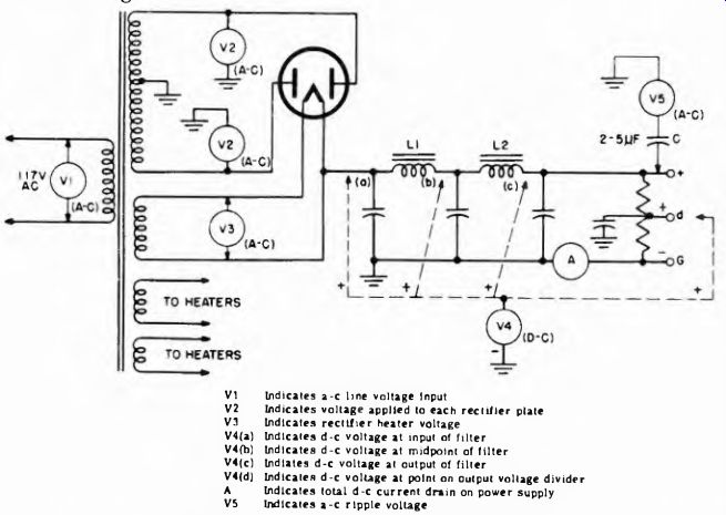
Fig. 10-44. Conventional full-wave B supply.
------------------
The precautions stated in connection with d-c operating voltage measurements on oscillation applies to the oscillator section of these dual functioning tube systems. It also should be realized that an in operative oscillator section will not prevent the presence of d-c operating voltages on the mixer section.
10-28. Measuring Voltages in Power Supplies
A variety of power supplies are used in electronic equipments. They are classified as low' voltage and high voltage. The low voltage supplies furnish outputs of from a few volts to several hundred, while high voltage power supplies furnish thousands of volts output.
Two power supplies are shown in Figs. 10-44 and 10-45. Both are full-wave rectifiers that typify low voltage systems. Dealing with Fig. 10-44 first, the primary voltage input to the power supply is measured...
----------------------
V1(a) Indicates input a-c voltage
V1(b) Indicates a-c voltage applied across rectifiers
V2(a) Indicates d-c voltage Input to filter
V2(b) Indicates d-c voltage output from filter
V3 Indicates a-c ripple in power supply output
A Indicates total d-c drain on power supply
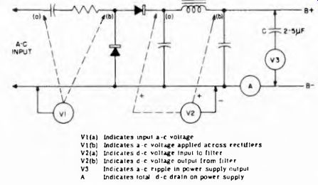
Fig. 10-45. Selenium rectifier power supply (full wave voltage doubler).
--------------------
... across the primary of the input power transformer. This is an a-c voltage and requires an a-c voltmeter (VI). The voltage fed to the rectifier tubes for conversion to pulsating de and subsequent filtering also is of an alternating character. It can be measured across each half of the high-voltage winding. The center tap can be a common point for these measurements (though not for the primary-voltage measurement). These meter connections are shown as V2. The heater voltage fed to the rectifier also is ac and secured from another winding on the transformer. An a-c voltmeter of suitable voltage rating is connected as is V3.
All of the a-c measurements on a power supply are made across relatively low resistance circuits, hence any conventional a-c meter of suitable accuracy and frequency rating can be used. The rectifier type is preferred. Since the output of the rectifier is a pulsating d-c voltage, it will be indicated on a d-c meter.
Since the power supply has a common ground for the entire filter system, ground can be the common reference point. All other points will be positive relative to ground. Therefore the negative terminal of the voltmeter V4 is joined to ground, and the voltages at different points in the filter system, and at the output, are determined by the roving positive lead. If the power supply contains a half-wave rectifier, voltage measurement proceeds as outlined above, except that fewer a-c measurements are made.
A simple full-wave selenium rectifier, "transformerless" voltage doubler power supply is shown in Fig. 10-45. The a-c voltage measuring points are shown by V1, and the d-c voltage measuring points are shown by V2. The ripple across the output is measured by connecting a low- voltage meter of the rectifier type in series with a 2 to 5 ^f capacitor across the output of the power supply, as shown by V3. The working voltage rating of the capacitor C should be twice the power supply output voltage.
----------------
V1 Indicates d-c voltage input to vibrator
V2 Indicates a-c voltage across each half of secondary winding
V3 (a) Indicates d-c voltage input to filter "
V3(b) Indicates d-c voltage at midpoint of filter
V3(c) Indicates d-c output voltage from filter
A1 Indicates the d-c current drain in the primary circuit
A2 Indicates the d-c current drain on the power supply
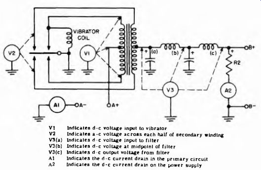
Fig. 10-46. Full wave synchronous vibrator power supply.
-----------
Numerous devices, especially mobile electronic equipment operated from a d-c source, use vibrator type power supplies. One example is given in Fig. 10-46; this is a full wave synchronous unit. The vibrator does the rectifying by being active in both the primary and secondary circuits of the transformer. Adjustment of the rectifier is usually done while using a scope, nevertheless voltage tests are useful as a rapid means of determining performance.
A nonsynchronous vibrator type of power supply differs from the synchronous type in that the vibrator is used only to interrupt the primary current. Rectification is done by a full-wave rectifier tube.
Dynamotor Power Supplies. Mobile electronic equipments occasionally use dynamotor power supplies. These are small motor generator units operated from 6-32 volt storage batteries, and furnishing d-c output at various voltage up to about 500 volts. They differ from the usual motor-generator unit in that a common field winding is employed for both. Schematically the dynamotor power supply appears in Fig. 10-47.
The application of voltage and current measuring devices is simple as indicated: Since all the circuits involved have low resistance, sensitivity of the voltage measuring devices is not a factor. The measurements should be made under rated current loads or otherwise the indications do not reflect the true performance of the device.
10-29. Measuring Operating Voltages in TV Receivers
The measurement of operating voltages (both de and ac) in television receivers is not unlike that in radio receivers or other electronic equipments which were described in Sections 10-22 through 10-27.
Fig. 10-47. Dynamotor power supply.
However, one particular portion of a television receiver requires special techniques and equipments for the measurement of the d-c voltages in the presence of a high a-c voltage which exists in it. This portion is the horizontal-output tube plate circuit, the horizontal-output system, and the high-voltage supply. These are symbolized in Fig. 10-48.
All horizontal-output systems may not be exactly like the one shown here, but the points indicated will be found in virtually all systems, hence the comments apply.
The plate (7) of the horizontal-output tube is subjected to a d-c operating voltage of from 250 to 500 volts. As a rule this voltage exceeds that available from the low voltage B-|- supply (4) by an amount corresponding to the "boost" voltage (5) developed in the damper systems across the "boost" capacitor.
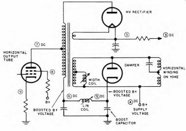
Fig. 10-48. Typical horizontal output system and high voltage supply.
-------------------
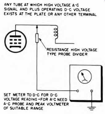
Fig. 10-49. Measuring d-c operating voltages where both a-c and d-c voltages
are present.
ANY TUBE AT WHICH HIGH VOLTAGE A'C SIGNAL AND PLUS OPERATING d-c VOLTAGE EXISTS AT THE PLATE OR ANY OTHER TERMINAL RESISTANCE HIGH VOLTAGE TYPE PROBE DIVIDER OF SUITABLE RANGE SET METER TO D-C FOR D-C VOLTAGE READING -FOR A-C NEED
A-C PROBE AND PEAK VOLTMETER
----------------
At the same time, the horizontal-output tube plate is also subjected to a very high a-c pulse of nonsymmetrical waveform. Hence two voltages exist simultaneously at this joint.
The measurement of the d-c operating voltage at the horizontal tube plate or at any point in the horizontal-output system where both d-c and a-c voltages exist can be accomplished as shown in Fig. 10-49.
The meter can be either a VOM or a VTVM. A high resistance d-c voltage divider probe with known voltage ratio is required between the horizontal tube plate and the meter. Only a fraction of the voltage at the probe tip appears across the meter. As a rule these probes afford about 100:1 ratio in voltage division. The meter should be adjusted to the 10 volt d-c scale. Using a probe of this kind will make the high a-c pulse voltage at the horizontal-output tube plate ineffective as far as the d-c meter is concerned. The operating d-c voltage is equal to the amount shown on the meter times the voltage divider ratio of the probe. The test point for this measurement is (7) in Fig. 10-49.
Other test points for d-c voltage measurements in horizontal-output systems are the screen grid (8) and the cathode (9) of the output tube; the low end of the horizontal-output transformer primary (6) in Fig. 10-48, the cathode of the damper tube (5) and the B-)~ supply feed point (4) . The divider probe is not required at these points, although no harm comes from using it; the VOM or the VTVM can be used directly. The voltages are approximately from 250 to 500 dc.
Sometimes the horizontal-output circuit is such that the plate of the damper tube is the low side. In this event the point (5) in Fig. 10-48 would be at the plate of the damper rather than at the cathode.
Measurements at joints corresponding to (6) or (5) and (4) indicate the un-boosted and boosted B voltage for the horizontal-output tube.
Points (6) and (7) would be subject to the same d-c voltage.
The high-voltage d-c probe is made of special insulating material, and is of special construction to afford protection against electric shock.
One example of such a high-voltage probe is shown in Fig. 10-50. It contains a network of high-value resistors, and only a small fraction of the total voltage applied across the divider appears across the voltmeter.
Another application for the high resistance voltage-divider probe is the measurement of the d-c output of the high-voltage power supply, which is the same as the second anode voltage. This too is shown in Fig. 10-48. The test points are labeled (3). Unlike the horizontal-output tube plate, where d-c voltages of from 250 to perhaps 500 volts are found, the d-c voltage at the output of the high-voltage power supply approximates from 8,000 to perhaps 18,000 volts, depending on the specific receiver. Hence the voltmeter range for a 100:1 divider probe should be the 250 or 300 volt scale in order to protect the instrument.
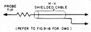
Fig. 10-50. Example of a high voltage probe.
High voltage measurements must be made very carefully, using a high voltage divider probe. It is a good idea when measuring voltages at high voltage points in a tv system to turn off the receiver first, connect the probe to the test point, and then turn the receiver on again.
Operating Voltages in Blocking Oscillators and Multivibrators. The measurement of d-c operating voltages at tube electrodes in blocking oscillators and multivibrators in television receivers is conventional, despite the fact that a-c signal voltages also are present. The a-c voltages at these points are not too high, and the fact that they approach a symmetrical waveform makes it possible to measure the d-c voltage without concern for the a-c which is present.
Operating d-c voltages which are of interest in blocking oscillators are the plate voltage, the control grid voltage, the cathode voltage, the a-c heater voltage, and such other voltage as may be listed in the reference information. The same is true of horizontal oscillators and multivibrators. It is essential to bear in mind that the grid, plate, and cathode electrode operating voltages encountered in these systems are subject to variations according to the setting of the associated controls.
Spurious Signal Pickup in TV Receivers. Spurious signal pickup with a rectifier probe will be plentiful in a television receiver. The strong field from the horizontal-output system will result in signal indications almost regardless of where the probe tip may be located. Hence, when attempting to make measurement with a rectifying probe or a peak- to-peak probe in a television receiver, it is advisable to first remove the horizontal oscillator tube, provided that this is not the system which is being tested.
When checking pulse amplitudes in the vertical integrator system it is advisable to remove the vertical oscillator, because signals from this tube find their way into the vertical integrator.
Adjusting 4.5 MC Trap. The crystal or diode probe used with a VTVM, or possibly with a VOM having a sufficiently low d-c scale (0-3 volts), can be used for the adjustment of traps if the probe tip is connected to points where a suitable signal exists. For instance, in intercarrier television receivers, the 4.5 mhz sound signal is not routed in the video system. Therefore the rectifier type probe voltmeter combination can be used in the video system when adjusting the 4.5-mc trap. The point of connection can be at the video signal input to the picture tube, provided that the peak voltage to ground at this point does not exceed the working voltage rating of the isolating capacitor in the probe. The meter indication should be minimum when the sound trap is properly adjusted. The 4.5-mc test signal is secured from a marker generator and fed into the video system ahead of the 4.5 mhz trap.
Care must be exercised when using r-f probes at plate circuits of i f amplifying tubes. The blocking capacitor in the probe has a peak voltage rating which should not be exceeded by the operating plate voltage applied to the tube, if damage to the capacitor is to be avoided.
Rectifying probes designed for + voltage output will give reversed readings if the isolating capacitor has excessive leakage and the probe is joined to a source of dc.
10-30, Alignment and Other Tuning Adjustment
The VOM and the VTVM are frequently used as indicators for peak type adjustments on tuned circuits, r-f, mixer, oscillator, and i-f coils and transformers, in radio, television, and other types of receivers.
They are located at points where, as the result of rectification in the electronic system, a d-c voltage is available, the magnitude of which voltage reflects the correctness of the tuned circuit adjustments.
The usual location of such indicating meters is across the second- detector load circuit in radio receivers, and across the video-detector load circuits in television receivers. In the latter instance it can be at the point of origin of the age voltage. Another location is across the limiter grid resistor.
When the indicating meter is a 20,000 ohms-per-volt instrument and is connected across a grid resistor in a tuned circuit, it is a good idea to use a 100,000-ohm isolating resistor in series with the ungrounded ...
----------------
V indicates grid voltage developed by limiter grid current. Adjust for maximum meter indication. Point X is location of isolating resistor for VOM.
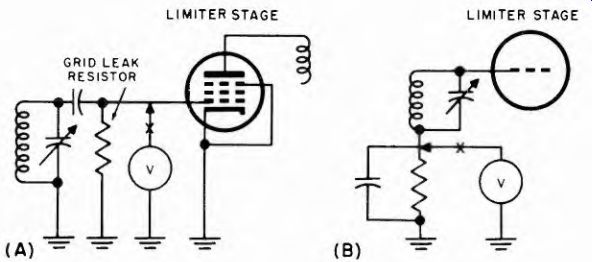
Fig. 10-51. Peak alignment of limiter stage.
------------------
... lead. Examples of this are shown in Fig. 10-51. Such a resistor is not needed when a VTVM is used because the usual d-c probe used with VTVMs contains a 1-meg isolating resistor.
When using a VOM or a VTVM as an indicating device during tuned circuit adjustments, it is a good idea to disable the avc and use a fixed bias of several volts instead. The receiver manufacturer's recommendations in this connection take precedence over anything said here.
10-31. Static and Dynamic Measurements on A-F Amplifiers
A-f amplifiers are found in all kinds of electronic devices, radio receivers, television receivers, public address systems, high fidelity reproducing systems, and others.
Meters are applied to these systems for two main purposes: (1) static measurements to check operating voltages and currents, and (2) to measure signal voltages. The oscilloscope is the preferred device for signal tracing because it shows waveform, but meters are also extensively used for signal measurement. As to meter devices used for this work, VTVMs are preferred for all high resistance control grid circuits; 20,000 ohm-per-volt instruments are usable but will not be as correct in their indications as VTVMs. In plate, screen, and cathode circuits either one will do.
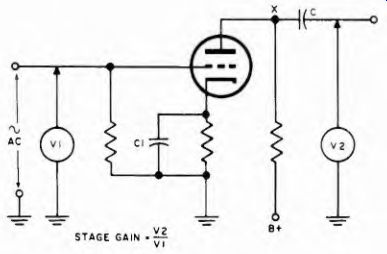
Fig. 10-52. Arrangement for measuring stage gain of an a-f amplifier using
a-c meters of suitable type.
Most a-f amplifier stages are resistance-coupled, except for the output stages. The schematic in Fig. 10-36 shows a typical resistance-coupled stage while Fig. 10-44 shows a class A push-pull stage. The principal points at which voltage and current readings can be made are shown.
Inasmuch as a push-pull system is supposed to be balanced to d-c and a-c voltages, the paired voltages V3 and V4 (Fig. 10-37) should be alike. Different readings indicate a difference in d-c resistance in the transformer windings, or unlike tube constants. The latter is particularly true in the case of the cathode voltage readings, which depend in great measure on the voltage drops across the two halves of the output transformer primary.
The push-pull stage shown in Fig. 10-37 can be a Class B system, or a Class AB system, in which event grid current flows during a portion of the input-signal voltage cycle. With signal input, the voltmeter V1 indication will not be zero voltage, nor will the readings on V3 be the same with or without signal voltage applied. Finally, V3 will not necessarily read the same as V2. The V1 indications will depend on the voltage drop developed across each half of the input transformer secondary by the grid current. In like manner, the difference between the V2 and V3 indications will depend on the amount of grid current.
10-32. Stage Gain
The gain in an a-f amplifier stage can be determined by measuring the signal voltage at a standard frequency, such as 400 hz, at the stage input and output, inclusive of the coupling system. The circuitry for an r-c coupled stage is shown in Fig. 10-52. The signal is measured with an a-c voltmeter (VI) of suitable input resistance. In view of the high value of grid leak usually used in these circuits, it is best if the measurement is made with a VTVM. The output signal is measured by V2. If the measuring instrument contains a blocking capacitor, the high side of the voltmeter can be connected at X, the top of the load resistor. If it does not incorporate the blocking capacitor, then the measurement should be made after the blocking capacitor C. The calculation of the stage gain is shown by the equation under the schematic in Fig. 10-24.
This is simply the ratio between the output and input signal voltages, and is the same for other type tubes.
A method of measuring gain in a transformer-coupled stage is shown in Fig. 10-53 (A). The points of measurement are the same as for the resistance-coupled stage, and the equation for stage gain is the same.
When this test is applied to a transformer-coupled push-pull system, the gain is measured as the ratio of plate-to-plate signal voltage to grid-to- grid signal voltage. (See Fig. 10-53B.)
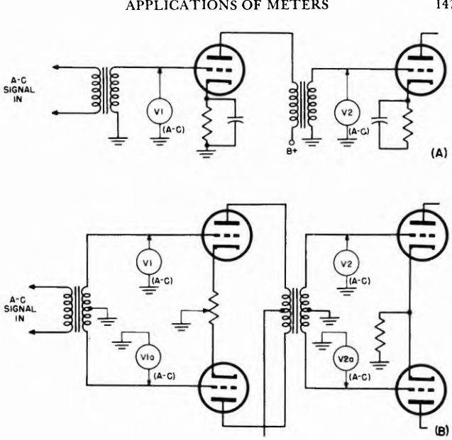
Fig. 10-53. Measuring gain in transformer-coupled amplifier.
10-33. Measuring Power Output
The arrangement shown in Fig. 10-54 is suitable for measuring the power output of any type of a-f amplifier. Output signal voltages can be measured across the loudspeaker voice coil, but uncontrollable variations in the acoustic loading of the speaker make it difficult to ascertain what the actual, resulting electrical voice coil load resistance is. Therefore, a non-inductive load resistor R is usually used to replace the loudspeaker or other output device. R has a value equal to the nominal impedance of the load.
Any rectifier-type meter or VTVM which measures a-c voltage at the desired frequency is satisfactory for this test. Since R is usually a replacement for the voice-coil impedance and is normally from 3.2 to 15 ohms, high meter sensitivity is not required.
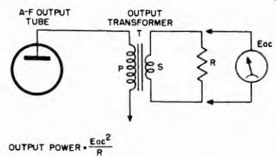
Fig. 10-54
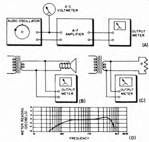
Fig. 10-55. Arrangements for making frequency-response measurements of an
a-f amplifier.
10-34. Frequency Response
The frequency response of an amplifier is usually expressed on a graph on which output is plotted against frequency, with the input signal voltage to the amplifier constant. The input signal level is kept at some value which provides rated power output, or some specified fraction thereof, at a standard frequency of 400 or 1,000 hz.
Figure 10-55 shows the arrangement. Various values of frequency covering the expected range are successively used, and the output for each noted. An example of a frequency response curve developed in this manner is shown in Fig. 10-55D.