AMAZON multi-meters discounts AMAZON oscilloscope discounts
A MODIFIED form of the familiar audio-frequency amplifier to be found in all radio receivers is the basis of public address systems. Essentially, a public address system is nothing more than a high-power audio frequency amplifier, to which has been added a microphone, loudspeaker, and perhaps a phonograph pickup. However, public address systems present their own particular difficulties, because they possess certain peculiarities which are not encountered in the audio-amplifier end of fl receiver. Nevertheless, signal tracing is equally applicable to public address systems and the application of signal tracing enables the rapid localization of defects.
The application of signal tracing to voltage and power amplifiers has already been described and thus there is no need to enter into a further discussion of such equipment at this point. In view of the fact, however, that the magnitudes of the signal voltages which appear in the audio-frequency section of a radio receiver differ considerably from those found in a public-address amplifier, it will be helpful to examine the magnitude of the a-f signal at various points.
In general, the block diagram in Fig. 8-1 may be considered a representation of a typical public address system. The relatively small output of the microphone is applied to a pre-amplifier stage which is used exclusively for the preliminary amplification of the signal produced by the microphone. The term "pre-amplifier" is occasionally used to signify an amplifier which is separated from the main amplifier. We are here using it in its broader meaning, namely, to signify any amplifier which is employed to raise the initially low voltage level of the microphone. The output of the pre-amplifier goes to a mixer to which there is also fed the output of a phonograph pickup, and, in some cases, the detector output of a radio receiver. Whether or not all of these units are employed is immaterial to our discussion and accordingly we show a mixer which is adapted for use with a single microphone and a single phonograph pickup.
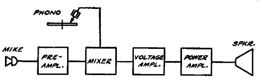
Fig. 8-1. Block diagram of a simple public address system.
After passing through the mixer, either the microphone signal voltage or the phonograph signal voltage, or both, depending upon the relative gain of these as determined by their respective volume-control settings, are fed into a voltage amplifier. After suitable amplification, the signal is delivered to a power amplifier which converts the voltage applied to its input circuit into electrical power which is then supplied to a loudspeaker. The loud speaker transforms this electrical power into acoustical power, so that an amplified version of the original sound wave which actuated the microphone is produced.
In the foregoing we have dealt only in generalities and have limited ourselves to a qualitative picture of the signal amplitudes.
We shall now concern ourselves with a quantitative view of a public address system; that is, we shall examine the magnitude of the signal voltage at various points in the system. The circuit, as shown in Fig. 8-2, is a simplified diagram of a commercial portable sound system. The modifications consist mainly in the elimination of certain portions of the circuit such as the power supply and tone control circuits, with which we are not concerned at the moment. This amplifier circuit is quite representative of modern p-a systems and has an average overall gain, for use with microphone input, of 128 db, and a gain, for use with a phono graph pickup, of 86 db.
Throughout this discussion we are describing the signal voltages appearing throughout the amplifier under working conditions. In testing an amplifier an a-f oscillator would replace the microphone in order to supply a voltage of constant amplitude to the amplifier.
Modem high-fidelity microphones, as ordinarily employed, supply the control grid of the input tube with approximately a one-millivolt signal. This signal level is supplied when the microphone is connected directly to the input circuit as would be the case with a crystal microphone, or through a transformer for a velocity or dynamic microphone. A voltage of this magnitude is generally too small to be capable of measurement with the instruments that are ordinarily available to the serviceman. Accordingly, even though the p-a system is in perfect working order, no measurable signal will appear at point 1.
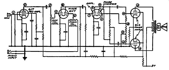
Fig. 8-2. Simplified diagram of a commercial portable sound system.
The distribution of signal levels throughout the amplifier is discussed in the text.
The voltage gain of the 6J7 stage of amplification is about 100, so at point 2 we may expect to find a signal voltage of one-tenth of a volt. Since negligible loss occurs through the coupling con denser, we therefore obtain a signal voltage of one-tenth volt at point S. The signal voltage at point 4 will depend upon the set ting of the volume control potentiometer and will range from zero to one-tenth volt. We shall assume a setting which will give a one-tenth volt reading at point 4.
At 5, likewise, the setting of the phonograph volume control potentiometer will determine the signal level at this point. This will range from zero to the maximum output voltage furnished by the pickup. In general a one-volt signal will be obtained from the pickup, whether connected directly to the amplifier as in the case of a crystal pickup, or indirectly when a magnetic pickup is employed in conjunction with a transformer. We shall assume that the phonograph pickup volume control potentiometer is set to provide one-tenth of a volt at point 5.
This first 6N7 tube is called a mixer stage since, by varying the voltage applied to the "microphone" grid at point 4 and the "phonograph" grid at point 5, the relative amplitudes of the microphone signal and phonograph signal may be varied, so that either one alone or both simultaneously will appear at the loud speaker.
Under the conditions of mixer operation the 6N7 has a voltage gain of about fifteen and a signal voltage of approximately 1.5 volts will result at point 6. Again there is no loss in the coupling condenser and consequently a 1.5-volt signal is obtained at point 7. The amplifier section of this second 6N7 tube, namely, the left hand section, has a voltage gain of twenty. Accordingly a signal voltage of 30 volts will appear at point 8, and this in turn is transferred to point 10.
We shall now digress momentarily in order to describe the phase-inversion action which occurs in the right-hand portion of the second 6N7. As was explained in the description of push-pull amplifiers earlier in this book, the signal voltage applied to the grid of one of the push-pull tubes must be 180 degrees out of phase with that applied to the grid of the other push-pull tube.
This condition will be met if the signal voltage at points 7 and 11 are 180 degrees out of phase.
In the section on amplifiers we have explained that the signal voltage at the plate of a vacuum tube is 180 degrees out of phase with the signal voltage applied to the grid of this same tube.
Accordingly, if to point 11, namely, the grid of the phase inverter section of the 6N7, we apply a signal that is 180 degrees out of phase with the signal voltage at point 7 we shall fulfill this requirement. This could be accomplished by taking the signal voltage from point 8, since the signal voltage at point 8 is 180 degrees out of phase with that at point 7.
Another requirement must be met, namely, the amplitude of the signal voltages applied to each of the push-pull grids must be equal. Therefore, instead of taking the signal voltage directly from point 8, we employ a voltage divider network 10-12 and 12-13. The magnitudes of the resistors between 10-12 and 12-13 are adjusted so as to give· a voltage at point 11 which is equal to that at point 7, namely, 1.5 volts. Consequently the signal voltages at 8 and 9 are equal in magnitude (30 volts) but 180 degrees out of phase. Similarly, the signal voltages applied to the grids of the push-pull tubes at points 10 and 14 are equal in amplitude and 180 degrees out of phase, namely 30 volts.
Assuming a voltage gain of six for the 6L6 tubes, the plate of each tube, as points 15 and 16, will show a signal voltage reading of 180 volts above ground potential. Of course the signal voltage across the voice coil will depend upon the voice coil impedance, as we explained in connection with power amplifiers.
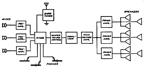
Fig. 8-3. Block diagram of a public-address system. Pro vision is made for
three separate microphone and phono graph channels.
Let us now consider the block diagram shown in Fig. 8-3. This represents a public-address system that is more complicated than those which we have previously considered. Besides providing for the reception of radio programs, three separate phonograph channels as well as three separate microphone channels are provided. The three microphones permit picking up announcements from different sources. Two of the phonographs are used in order to provide for continuous phonograph reproduction and to pre vent the interruption that would occur at the end of each record if but one phonograph pickup and turntable were employed. The third phonograph is utilized for the injection of sound effects.
The radio tuner and the phonograph and microphone circuits are all connected to a mixer which regulates the relative amplitudes of the signals from the various components. The output of the mixer then goes to a master gain control which controls the overall gain of the entire system. From here the signal enters an equalizer which is nothing more than a tone control circuit designed to give an accurate control of the frequency response of the system. The signal now enters the main voltage amplifier where the signal voltage is stepped up sufficiently to be delivered to the power amplifiers.
The question might be asked why one power amplifier, rather than three, is not used to supply all the loudspeakers. There are two principal reasons for this. A single power amplifier which was capable of supplying the same power output would be considerably more than three times as expensive as the three separate amplifiers. Furthermore, the use of three amplifiers, rather than one, introduces an element of safety. Where a single power amplifier is used its breakdown would terminate operation of the entire system. However, when three separate power amplifiers are used the breakdown of one of them does not cause the entire system to become inoperative but only those loudspeakers connected to the defective power amplifier.
Although this system appears much more complicated than the circuits previously discussed, actually this is not the case, at least, insofar as signal tracing is concerned. It is true that the number of test points is increased, but the signal tracing method of trouble localization is exactly the same.
We are not here concerned with the minute details of public address systems and the many modifications in design and layout which occur. Our major interest is in the application of signal tracing in such systems. Only the broad outlines of this technique have been described in this section and the reader is referred to Section 2 for a more detailed treatment of amplifiers.