AMAZON multi-meters discounts AMAZON oscilloscope discounts
4-1. Functions and Action of Isolation Resistor In VTVM D-C Probe
The simplest and perhaps most widely used d-c circuit-isolation arrangement is that provided by the 1-megohm resistor which is included in the d-c probe of practically all service-type vtvm's, as illustrated in Fig. 4-1, for use on the d-c voltage ranges. This isolating resistor has two important functions: (1) it greatly reduces the effective over-all input capacitance presented to the circuit under test by the d-c probe; (2) it comprises part of a resistance-capacitance input filter circuit which filters out any strong high-frequency a-c components that may be present in the d-c voltage that is to be measured, thus preventing them from reaching the metering circuit, so that d-c voltages can be measured in the presence of high-frequency a-c.
(1) Action as a Circuit-Isolation Resistor. The input voltage-divider resistance network, shielded input cable, and test prod of a vtvm have a combined over-all capacitance which may total approximately 60 to 120 µµf or more. If so isolation resistor were used, this capacitance would be applied directly across the circuit whose d-c voltage was being checked, as shown in Fig. 4-2A. Such a large value of shunting capacitance will cause severe capacitive loading and disturbance of the normal circuit operation of many of the r-f circuits whose d-c voltages need to be checked with the vtvm, resulting in erroneous and misleading d-c voltage readings. An example is provided by an attempt to measure the signal-developed d-c bias voltage at the control-grid of a high-frequency oscillator. It is not practical to dispense with the shielded cable in an effort to reduce the capacitance, since excessive spurious voltages would often be induced in an unshielded cable by the strong stray fields existing around the equipment under test. The problem is solved by inserting a suitable isolating resistor R (sec Fig-. 4-2B), having a value of approximately 1 megohm, in series with the input circuit, between the shielded cable and the test point in the receiver. The most satisfactory arrangement is to mount it within the d-c probe head, as shown in Fig. 4-1.
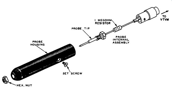
Fig. 4-1. Exploded view of typical vtvm d-c probe containing a 1-megonm series
connected isolating resistor. The particular probe illustrated here is designed
to be slipped on to a standard direct-probe and cable whenever d-c voltages
are to be measured. Courtesy: RCA.
As indicated in Fig. 4-2B, the effect of introducing the large-value isolation resistance at this particular point in the circuit is to place it in series with the reactance of the over-all input capacitance C. When a resistor is connected in series with a capacitor, the series combination has an impedance larger than the reactance of the capacitor alone, for any given frequency. Therefore, the addition of this isolation resistor greatly increases the impedance of the input circuit as seen from the probe tip. This is equivalent to saying that the input capacitance has been reduced in effect, to a value C1, whose reactance is equivalent to this impedance at the particular frequency being considered. Reduction of the effective input capacitance at the probe tip to a value of only 1 or 2 µµf is common, as shown in Fig. 4-2C. Of course, the probe assembly has a certain amount of stray capacitance from its input to its output circuit, and from its input to ground, which is included in this effective input capacitance. Obviously, these two stray capacitances should be kept as small as possible by proper physical de sign of the probe.
Another viewpoint regarding the effect of the isolating resistor is that its resistance value is sufficiently high (usually about I megohm) to provide protection against the shunting effect of the low impedance presented by the cable at high frequencies. The isolating resistor stands between the high-frequency voltages in the circuit under test, and the low impedance presented by the input end of the cable, which may drop to as low as 75 ohms at high tv frequencies.
Its practical effect is to provide negligible capacitive circuit-loading and resonance effects for most vtvm d-c voltage measurements made in radio-frequency circuits, so that little or no detuning, or other disturbance, of such circuits under test is caused by connection of the d-c probe of the vtvm to a load-sensitive point in the circuit. Addition of this 1-meg resistor in series with the usual 10- or 25-meg input network resistance of most vtvm's, see Fig. 4-2B, results in a total d-c input resistance of 11 or 26 megohms, respectively, which is great enough to prevent serious resistive loading of most tested d-c circuits, including d-c grid bias circuits.
(2) Action as a High-Frequency Filter. It is quickly seen that the combination of the series isolating resistor with the over-all shunt input capacitance, C, (Fig. 4-2B), also forms a low-pass resistance-capacitance filter, which causes the components to act as a voltage divider for a-c potentials. When the frequency is fairly low, the capacitive reactance is fairly high, so that the isolating resistor does not drop very much applied a-c voltage. When the frequency is higher, the capacitive reactance becomes fairly low, so that the isolating resistor drops practically all of any applied a-c voltage, causing it to become impossible to maintain an appreciable proportion of this voltage across the cable input. This provides sufficient high-frequency attenuation to keep any strong high-frequency components (such as rf) that may be present in the d-c voltage under test from entering the metering circuit. Here they might drive the metering-tube bias beyond cutoff and cause rectification, which would result in a change in the meter reading.
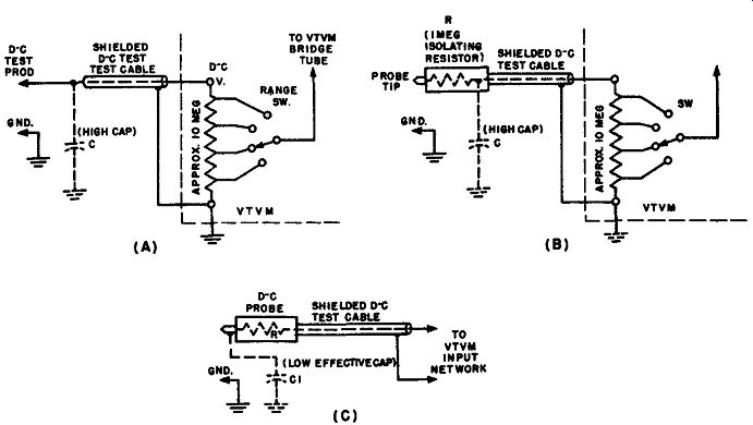
Fig. 4-2. The isolation resistor used with the d-c voltage function of a vtvm
usually consists of a carbon resistor having a value of approximately 1 megohm
connected in series with the "hot" lead of the input cable at the
probe. Its effect is to greatly decrease the effective input capacitance and
capacitive loading imposed upon the circuit under test. This resistor also
forms part of a R-C filter which keeps possible strong a-c components present
in the d-c voltage under test from entering the meter.
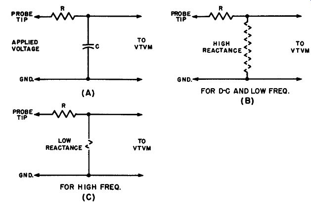
Fig. 4-3. Resistive-isolation probe circuit action which illustrates why the
high frequencies are discriminated against when an attempt is made to employ
a resistive isolation probe to minimize the loading effect of the cable capacitance
upon the circuit under test during high-frequency a-c voltage measurements
made with a vtvm.
4-2. Effect of Isolation Resistor on D-C Voltage Calibration of the VTVM
It will be observed in Fig. 4-2B that the isolating resistor is in series with the resistors that form the voltage-dividing network across the vtvm input. The resistance of the latter is 10 megohms in many commercial vtvm's. Consequently, a portion (about 10 percent in this case) of the applied d-c voltage that is to be measured will appear as a voltage drop across the isolating resistor, and the remainder (about 90 percent) will be applied to the vtvm. This reduces the meter deflection produced for a given input test voltage.
This matter is of no concern to the user of a vtvm if the isolating probe was supplied by the manufacturer as standard equipment with the meter, for in that case the d-c calibration of the meter already takes into consideration the total resistance of the input voltage divider of the meter plus the isolating resistor.
However, if the user wishes to add an isolating resistor to the d-c test prod of a vtvm which does not already employ one, or if he decides to increase the value of the isolation resistor already in a probe in order to obtain improved isolation through the use of a higher resistance, he must remember that the addition of the resistor will cause the d-c voltage scale indication to read low. The amount of correction that must be applied can be calculated on a percentage basis by proper consideration of the voltage division in the series-resistor circuit (see Fig. 4-2B).
4-3. Why Use of a Circuit-Isolation Resistor is not practicable for High-Frequency A-C Voltage Measurements
It is quite essential that the user of a vtvm or a scope remember that the isolation resistor. is used only when d-c (or low-frequency a-c) voltage measurements are to be made. The beginner sometimes is inclined to overlook this important limitation, and attempts to use an isolating resistor with a vtvm (or a scope) in the measurement of high-frequency a-c voltages, in order to reduce capacitive-loading effects. Such attempts can only result in erroneous readings.
First of all, the fact that the a-c scales of the vtvm have been calibrated on the basis that no series isolating resistor is in the circuit when a-c measurements are being made, should be a sufficient reason not to introduce an isolating resistor into this circuit. Also, let us redraw the combination of isolating resistor, R, and over-all input-circuit capacitance, C, as in Fig. 4-3A, so that its low-pass filter characteristics may be emphasized.
For input voltage of zero frequency (dc), and low frequencies, the reactance of capacitor C is so high that the proper proportion of the applied voltage appears across this capacitance and is applied to the vtvm. Consequently, since d-c voltage, and low-frequency a-c voltage, is passed with little alteration by this filter (except for the drop across R. which is taken care of in the meter calibration), fairly accurate measurements of voltages of these frequencies may be made.
As the frequency of voltage to be measured is increased, the reactance of C diminishes, and it can reach quite low values at radio frequencies. Under these conditions, the combination operates as a voltage divider, and the voltage step down ratio increases with the frequency. Consequently, the a-c voltage actually made available to the vtvm input terminals becomes increasingly less than that applied to the probe for measurement, and the ratio of the two varies with the frequency. As a result of this action, at high frequencies the a-c voltage level in the cable (and applied to the vtvm) may diminish to an insignificant value. It is obvious that accurate measurement of high-frequency a-c voltage is impossible under these conditions.
The fact that a resistive isolating probe discriminates against the higher frequencies is demonstrated experimentally by Fig. 4-4, which shows that the higher frequency components of a square wave are attenuated in passing through such a probe. When it is desired to minimize the capacitive-loading effect of the cable capacitance upon the circuit under test during a-c voltage measurements made with a vtvm, it is accordingly necessary to utilize other means than an isolating resistor.
In some cases, a resistive isolation probe is capacitance compensated to avoid this frequency distortion when measuring a-c voltages at frequencies within the range of vtvm a-c voltage response.
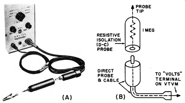
Fig. 4-5. (A) Separable-probe arrangement used for vtvm resistive isolation
(d-c) probe. Provides d-c and a-c voltage test facilities with one test
cable. ( B) Circuit arrangement of separable probe and test cable. (A) Courtesy:
RCA
4-4. Substitution, and D-C/A-C Switching, Arrangements for VTVM D-C Probes
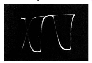
Fig. 4-4. The frequency discrimination resulting from the use of a resistive
isolation probe in high-frequency a-c voltage measurements is shown here. A
low-frequency square wave a-c voltage was applied to a resistive isolating
probe and shielded test cable connected to the scope input. The severe rounding
of the corners of the reproduced wave indicates discrimination against the
high-frequency components of the square wave by the probe and cable.
The modern trend in high-speed signal tracing and voltage-checking with the vtvm is toward the use of a single test cable for as many meter functions as possible in order to eliminate much of the complication and loss of time experienced with a meter having numerous leads which invariably become tangled.
This poses a problem in connection with use of the resistive-isolation probe for all d-c voltage measurements made with the vtvm. The resistor must not be in the voltage-measuring circuit when a-c voltage measurements arc being made.
However, most service-type vtvm's provide only a single "Volts" terminal for both d-c and a-c voltage measurements. The d-c or the a-c voltage measuring function must be selected by the selector switch on the instrument.
This problem is solved in two ways, in practice. One arrangement is illustrated in Fig. 4-5A. When a-c voltage measurements are to be made, a direct cable and probe, shown at the lower right, is used. When d-c voltage measurements arc to be made, a separable probe head containing the 1-megohm isolating resistor (shown to the left of the direct cable and probe) is slipped on to the direct probe, thereby connecting it in series with the "hot" lead of the cable, as shown in Fig. 4-5B. Another electrically equivalent arrangement is illustrated in Fig. 4-6. The 560,000-ohm resistor for this vtvm is contained within the probe, and it may be switched into the circuit when d-c voltages are to be measured and out of the circuit when low-frequency a-c voltages arc to be measured (sec Fig. 4-6B). The simple slide switch is conveniently located on the probe housing for rapid manipulation. A modification of this method is also in use where the switch is arranged to short-circuit the isolating resistor. This switch may take the form of a small sleeve on the probe which may be screwed in tight to short-circuit the resistor or unscrewed to remove the short.
4-5. Use of Resistive-Isolation (D-C) Probe with a VOM
A resistive isolating probe cannot usually be used successfully with a vom because the relatively large current drain of the instrument causes excessive voltage drop across the isolating resistor. Furthermore, an isolating resistor which is chosen to provide direct readings on one range, will read incorrectly on the next higher range, because the input resistance of a vom is not constant as is that of a vtvm. The input resistance on any one range is equal to the full-scale value of the range times the ohms-per-volt rating of the instrument. For example, a 100,000 ohms-per-volt vom has an input resistance of I megohm on the 10-volt range, and an input resistance of 10 megohms on the 100-volt range.
Consider the input resistance of a 20,000 ohms-per-volt vom on the 3-volt range with respect to the resistance of the isolating probe. While the instrument has an input resistance of only 60,000 ohms for this range, the probe has a resistance of approximately 1 megohm. Hence, much more of the voltage to be measured is lost in the probe than is made available to the vom.
It might be supposed that the use of a 100,000 ohms-per-volt vom would make the use of a resistive isolating probe more practical, but even in this case, the input resistance of the meter on the 3-volt range is 300,000 ohms, as compared with the 1-megohm resistance of the usual isolating probe. The value of the isolating resistor can be reduced to about 300,000 ohms, thus obtaining an appreciable degree of isolation, at the expense of half the sensitivity of the meter (see Sec. 4-2).
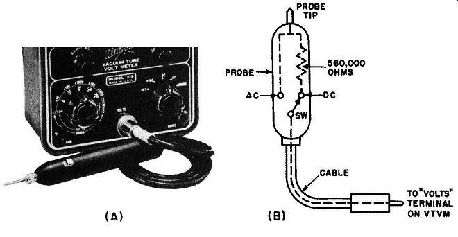
Fig. 4-6. Slide-switch arrangement used on vtvm resistive isolation ( d-c)
probe to provide d-c and a-c voltage test facilities using one test cable.
( B) Switching circuit. (A) Courtesy: Hickok Elect. Instr. Co.
4-6. Erroneous Use of Resistive-Isolation (D-C) Probe in Low-Voltage D-C Circuits Containing High-Voltage Pulses
Another error in probe selection concerns the common mistake of attempting to measure the d-c voltage at the plate of the horizontal-output tube of a tv receiver with a vtvm and its conventional d-c (isolating) probe containing a 1-meg resistor. This practice may lead to burn-out of the isolating probe, and often to damage of the vtvm input circuit also (punctured bypass capacitors, and overheated multiplier resistors). The reason for this damage is that in this particular type of circuit, although the d-c voltage may be of the order of 300 or 400 volts, there is an accompanying pulse voltage of the order of 4,000 to 6,000 peak-to-peak volts. The proper probe to use is a high-voltage d-c probe (which has a much higher resistance of the order of several hundred megohms) as is explained in Sec. 1-7. This higher resistance provides the necessary low-pass filter action required to attenuate the high-voltage a-c pulses so that they do not read1 the meter.
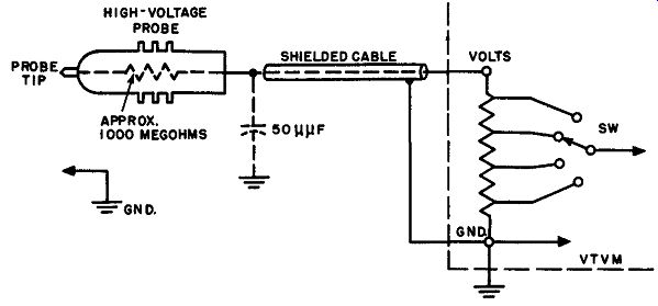
Fig. 4-7. Equivalent circuit of a high-voltage d-c probe, with shielded input
cable, working into the input resistance network of a vtvm. The shielded cable
and vtvm may have an overall input capacitance of say 50 µµf, which has a reactance
of 0.2 megohm at 15,750 hz. A 100-to-1 high-voltage probe makes it possible
to measure d-c plate-voltage values in the 15,750 hz horizontal-output circuits,
without damage to the vtvm from the accompanying high-voltage pulses. The attenuation
of the pulses in this case is in the order of 1,000 to 0.2 or 5,000 to 1.
4-7. Erroneous use of Resistive-Isolation (D-C) Probe In High-Impedance Circuits
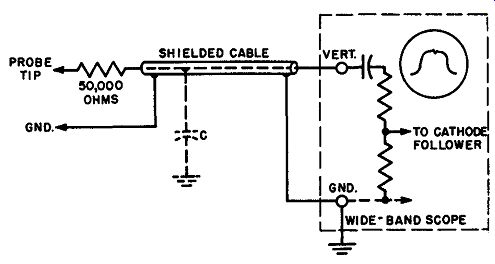
Fig. 4-8. Use of an isolating resistor with scope to produce sharp markers
in visual alignment work.
Another type of error in probe application occurs in the attempt of the technician to measure the d-c bias voltage at the grid of a vertical blocking oscillator with a vtvm and its conventional d-c (isolating) probe containing a 1-meg resistor. If the impedance of the grid circuit is very high, as is often the case, the voltage reading is falsely subnormal due to circuit loading caused by the insufficient impedance of the probe input circuit. Here again, the proper procedure is to use a 100-to-1 high-voltage d-c probe with the vtvm, as illustrated in Fig. 4-7. This will permit the bias to be read on the 3-volt scale (as a 300-volt scale) with an input resistance of more than 1,000 megohms.
4-8. Use of Isolation Resistor with Scope to Sharpen Marker Pips during Visual Alignment
An isolation resistor is very helpful in visual circuit-alignment work with a scope because it operates in combination with the overall capacitance, C, of the shielded cable and scope input circuit to filter out the high-frequency beat components, thereby sharpening broad marker pips which would otherwise mask important portions of the response traces. The marker is sharpened without producing reactive distortion of the resonance curve, or displacement of the marker.
A value of 50,000 ohms connected in the "hot" input lead of the scope, as shown in Fig. 4-8, is recommended for use with the average length of shielded cable.
The effect of using such a probe to sharpen the marker display is illustrated in Fig. 4-9.
Fig. 4-9. Example of isolating-resistor use with scope in visual alignment work.
Unless a suitable probe is used at the output of the picture detector when displaying a visual-response curve and marker indication, the marker may be unsatisfactory, or the curve may be distorted, or both. For example, if a 10-10-1 low-capacitance probe is used (see Sect. 5), its wide frequency response results in display of the higher beat frequencies, and a broad fuzzy marker indication is developed, as shown in (A). When a direct probe is used, fewer of the higher beat frequencies are re produced, but a satisfactory sharp marker is still not developed, as shown at ( B). When a resistive isolating probe is used, the marker indication is quite sharp and satisfactory, as shown in (C).
This isolation-resistor arrangement is not suitable for use in waveform checking in sync and sweep circuits of tv receivers, because the waveforms in these circuits will usually appear badly distorted when it is used. The reason for this is that troubleshooting in sync and sweep circuits requires wide frequency response instead of the comparatively narrow frequency response that is sufficient for visual alignment. The filtering action of the isolation resistor in combination with overall capacitance, C, (Fig. 4-8) results in high-frequency discrimination (see Sec. 4-3) with resulting narrowing of the frequency response. Consequently, a compensated high-impedance probe is required in this type of work, instead of a simple isolation resistor.
4-9. Use of Isolation Resistor with Scope in Front-End Signal Tracing
To determine whether the antenna signal is proceeding through the r-f stage to the mixer grid, it is usually possible to sweep the antenna terminals and check the "looker" point on the mixer grid lead with a scope. In some cases this looker point provides ample isolation from the capacitance of the scope cable, but in other cases an isolating resistor of about 50,000 ohms should be used at the end of the scope cable. This will avoid loading of the mixer grid circuit and detuning of the grid coil. In case of doubt, always include an isolating resistor in the test setup.
If the r-f stage is operating properly, a response curve will be obtained when a sweep-frequency signal is applied to the antenna terminals of the front encl.
A response curve of larger amplitude usually results when the local oscillator is disabled, because the local oscillator biases the mixer to a relatively insensitive operating point.