8. The Half-Wave Rectifier
A single diode is known as a half-wave rectifier since it permits current to pass only during the positive half-cycle of an applied AC voltage. A half-wave rectifier circuit with its input and output waveforms is shown in Fig. 5. An AC input voltage, usually derived from a power transformer, is applied in series with the diode rectifier and a load resistance. Plate current (Ib) flows through the tube and load every other half-cycle during positive alternations of the input voltage, and is blocked during the negative half cycles. Although unidirectional, the load current is not DC because of its pulsations in amplitude. It can be shown mathematically that these pulsations contain both a DC component and an AC component, known as ripple. The current can be converted into a steady DC by filtering out the AC ripple with suitable smoothing filters. (See Chap. 4.) It is evident from Fig. 5 that during the time that plate current flows, its instantaneous magnitude follows exactly the changes in the applied voltage. The shape of the plate-current waveform, therefore, is an exact replica of the AC input voltage waveform during positive half-cycles. The plate current develops a DC output voltage across the load resistance as it flows through it. The waveform (not shown) is exactly the same as that of the AC input voltage, except that only the positive half-cycles are reproduced. Since one-half of the input voltage is lost, the efficiency of the half-wave rectifier is low.
When the plate-current waveform of the half-wave rectifier (Fig. 5) is averaged out over one complete cycle, it is found that the average current flowing through the tube is only 0.318 times the peak amplitude of the current. This means that a line drawn at 0.318 times the height of the peak current amplitude represents the average or steady direct current flowing through the tube.
Exactly the same is true for the DC output voltage. The average value of the pulsating DC output voltage is again only 0.318 times the value of the peak voltage appearing across the transformer secondary winding. (This theoretical value neglects the voltage drop in the transformer secondary and the voltage drop lost across the tube.) If the load draws a considerable current, the output voltage drops to an even lower value because of the increased drops across the tube and the transformer secondary.
Example: As a practical example, let us consider the half-wave rectifier circuit shown in Fig. 6, which employs a type 6W4-GT vacuum diode and a step-up power transformer with a 350-volt secondary plate winding.
Another secondary, called the filament winding, supplies 6.3 volts AC to the heater of the rectifier tube.
The root-mean-square (rms) value of the applied plate voltage across the transformer secondary must be multiplied by 1.414 to obtain the peak value of the applied AC voltage. We thus obtain 1.414 x 350, or 495 volts peak AC voltage. The average or DC output voltage, however, is only 0.318 times the peak value, or 0.318 x 495=156 volts. If we multiply the two factors together right away, we would see that the DC output voltage is only 0.45 times the rms value of the applied AC voltage (i.e., 1.414 x 0.318=0.45)
Equivalently, the rms value of the applied AC voltage must be 1/0.45, or 2.22 times the value of the desired DC output voltage.
The DC output voltage of 156 volts in Fig. 6 represents a theoretical or maximum value. In practice, the voltage will be considerably lower because of the tube voltage drop and the voltage lost in the transformer secondary winding which we have neglected. More over, when considerable load current is drawn, these voltage drops will increase and subtract still more from the available DC output voltage. However, the no-load DC output voltage of the circuit in Fig. 6 may actually rise above the rms value of the applied AC voltage when a suitable filter is connected across the output of the rectifier. This is because most filters employ capacitors that charge up to the peak value of the output-voltage pulsations and substantially maintain this value when the plate current drops to zero during negative half-cycles. The poor regulation of the circuit will not maintain a high output voltage when large load currents are drawn through the lube.
Limitations and Uses. We have already seen that a half-wave rectifier makes poor use of the AC supply, since it delivers power only half the time, during positive alternations of the supply voltage. As a result the ratio of the peak currents and voltages to the average current is high, the efficiency low, and the regulation poor. Half-wave rectifiers are not used, therefore, when more than a few-milliamperes load current is required. They are suitable ...
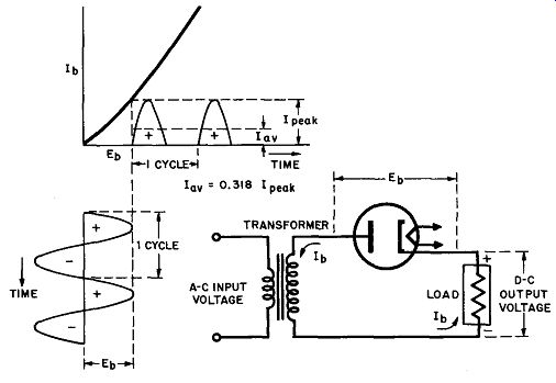
Fig. 5. Basic circuit and load current waveform of half-wave rectifier.
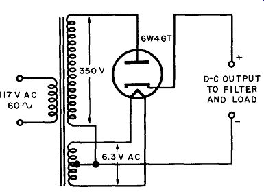
Fig. 6. Practical half-wave rectifier circuit.
... for applications requiring a small current drain, such as accelerating anode (ultor voltage) supply of oscilloscopes and TV picture tubes.
Perhaps the largest application of half-wave rectifiers is for the power supplies of ac-dc radios. Probably better than 90% of the radios made today use half-wave rectifiers because the current drain is relatively low and the 60-cycle response is very poor.
Therefore, the 60-cycle hum voltage is not very troublesome.
Another disadvantage of half-wave rectifiers is that the output current pulsates at the same frequency as the AC power line.
Elaborate filter circuits are required to eliminate this low-frequency ripple and produce smooth direct current. Finally, note in Figs. 5 and 6 that the rectified output current flows through the secondary winding of the power transformer. This results in a DC magnetization which saturates the core of the power transformer.
The efficiency of the transformer is considerably reduced and its expense goes up. The full-wave and other rectifier circuits, to be discussed next, avoid saturating the core of the power transformer by balancing out the DC magnetization with opposing currents.
9. The Full-Wave Rectifier
Plate current can be made to flow during the full cycle of the AC supply voltage by the use of two diode half-wave rectifiers in a full-wave rectifier circuit (Fig. 7). The tubes alternately supply rectified current to the load during both halves of the AC input voltage in such a way that the load current always flows in the same direction.
Note in Fig. 7 that the cathodes of the two rectifier tubes are tied together and the common junction is connected to one side of the load resistor. The other end of the load is connected to the centertap (C) of the secondary winding of the power transformer.
(Two separate windings can be used instead of a single center tapped winding.) Only one-half of the transformer secondary voltage appears between plate and cathode of each rectifier tube since each tube is connected between one end of the winding and a point midway in voltage (the centertap). This means that the transformer secondary winding must supply a plate-to-plate voltage that is twice the value of the plate voltage required for each tube. To provide sufficient plate and output voltage, the transformer usually has a considerable step-up ratio between primary and secondary winding.
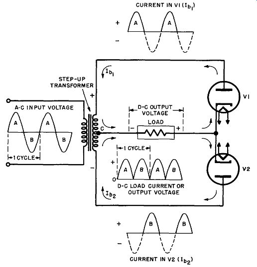
Fig. 7. Basic circuit and waveforms of full-wave rectifier.
When an AC voltage is applied to the primary winding of the transformer, a voltage of the same shape (shown in Fig. 7), but enlarged in amplitude appears across the secondary winding. This secondary voltage is split in half, one-half appearing across V1 in series with the load, the other half appearing across V2 in series with the load. Assume that the polarities cause the top of the transformer secondary to be initially positive during the first half-cycle, (A), of the AC supply voltage. The plate of V1 is therefore positive with respect to the cathode junction. A plate current (Ib1) flows from the cathode to the plate of V1, through the top half of the transformer secondary, and through the load, in the direction indicated by the top arrows. This current develops a voltage across the load, indicated by the half-cycle (A) in the output voltage waveform (Fig. 7). The direction of the current makes the cathode-end of the load positive. (Electron current flows from minus to plus.) Note that during this first half-cycle (A) of the input voltage, the bottom of the transformer secondary is negative with respect to the centertap, hence the plate of V2 is negative. No plate current flows through V2 during this half-cycle.
During the second half-cycle (B) of the AC input voltage the top of the transformer secondary will be negative with respect to the centertap. The plate of V1 is negative with respect to its cathode and no plate current flows. This is indicated by the dotted line for the negative half-cycle of Ib1• During this same half-cycle, the bottom of the secondary winding is positive as is the plate of V2 with respect to the cathode junction. Consequently a plate current (I_b2) flows from the cathode to the plate of V2, then through the bottom half of the transformer secondary and through the load, in the direction indicated by the bottom arrows. It is evident that the current flows in the same direction through the load as it did during the previous half-cycle. Thus two positive half-cycles (A and B) appear across the load during one AC cycle of the input voltage.
During succeeding half-cycles (A and B) of the input voltage, V1 and V2 continue to conduct alternately, each permitting current to flow during the half-cycle where its plate is positive with respect to the cathode junction. Since there are two output pulses for each complete cycle of the input voltage, the current through the load is a series of unidirectional pulses which have a frequency twice that of the AC supply frequency. With the ripple frequency twice that of the AC input voltage and the current much less discontinuous than that of the half-wave rectifier, the pulsations are easily smoothed out by a suitable filter circuit. Furthermore, the efficiency of the full-wave rectifier is far greater than that of the half-wave type.
Since there are two output pulses for each AC cycle, compared to only one in the half-wave rectifier, the average current value of the full-wave rectifier is twice that of the half-wave rectifier, or 0.636 times the peak current value. Similarly, the average of the output voltage is twice that of the half-wave rectifier for the same input, or 0.636 times the peak voltage value. Since the peak voltage is 1.414 times the rms voltage across the transformer secondary, the average output voltage is 1.414 x 0.636, or 0.9 times the rms value of the secondary voltage (across one-half of the winding). Equivalently, the rms voltage across one-half of the transformer secondary must be 1 /0.9 or 1.1 times the desired average value of the output voltage, or only one-half that required for a half-wave rectifier. (Across the entire secondary the value is the same as for a half-wave rectifier.) Note in Fig. 7 that when V1 is conducting, its cathode is at a positive potential almost equal to the peak value of the transformer secondary voltage (except for the tube drop). The cathode of (nonconducting) V2, therefore, is at the same high positive potential, while at the same time its plate is at a high negative potential equal to the peak value of the transformer secondary ...
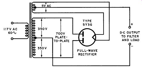
Fig. 8. Practical full-wave rectifier circuit.
... voltage. The same is true when V2 is conducting and V1 is nonconducting. The rectifier tube used in a full-wave circuit must therefore be able to withstand an inverse voltage of almost twice the peak of the secondary voltage applied to each tube separately.
Example: Let us compare the practical full-wave rectifier circuit shown in Fig. 8 with the half-wave rectifier illustrated in Fig. 6. A type 5Y3-G duplex diode (combining two diodes in one envelope) is used in connection with a center-tapped step-up transformer. The transformer secondary supplies 350 volts to each plate, or a total of 700 volts, plate-to-plate. A separate 5-volt secondary winding supplies the filament of the tube. The center-tapped heater winding is the ideal circuit, but many manufacturers dispense with the centertap (for cost reasons) and B+ is taken directly from one side of the heater.
The (theoretical) average value of the DC output voltage is 0.9 times the rms value of the plate voltage, or 0.9 x 350=315 volts.
This is about twice the average DC voltage obtained in the half wave rectifier for the same rms plate voltage. (For two tubes the plate-to-plate voltage is 700 volts, or double the value required for the half-wave rectifier circuit.) The theoretical value of 315 volts is not realized in practice because of the voltage drops across the tube and transformer secondary. Tube manuals list an actual value of 270 volts average DC output voltage (into a choke-input filter) for a load current at 75 ma. When the load current is increased to its maximum value of 150 ma, the regulation of the circuit (additional tube and transformer drops) reduces the available output voltage by another 25 volts, or to about 245 volts. This is still higher than the output voltage obtained for the half-wave rectifier circuit. Also, the current drain permissible for the full-wave circuit is far higher than that of the equivalent half-wave circuit.
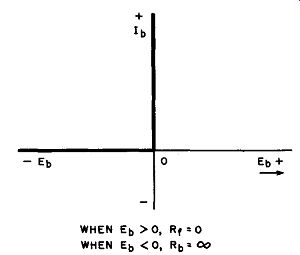
Fig. 9. Rectifier tube with indirectly heated cathode.
Advantages and Uses. Although we have neglected to mention it thus far, you may have noted in Fig. 7 that the individual tube currents of the full-wave rectifier flow in opposite directions through the secondary winding of the power transformer. This avoids the DC magnetization and resultant saturation of the transformer core, one of the serious defects of the half-wave circuit. This advantage, combined with the high-efficiency high-permissible current drain, less ripple (at twice the AC frequency), and relatively high DC output voltage, makes the full-wave rectifier circuit suitable for a wide variety of applications in electronics.
It is the standard circuit for low-power applications.
A slight variation (Fig. 9) in conventional rectifier circuits is found in the use of rectifier tubes having an indirectly heated cathode. When using such a tube as the 6X5-GT, it is unnecessary to have a separate filament or heater winding. The heater of this tube is supplied directly from the same heater winding that feeds the other tubes in the associated circuitry.
10. The Full-Wave Bridge Rectifier
The need for a center-tapped power transformer is eliminated by the bridge rectifier, in which four diodes are used (Fig. 10). As illustrated, the input to the bridge circuit is applied to diagonally opposite corners of the network, while the output to the load is taken from the remaining two corners. The circuit is a full-wave type, since both halves of the AC input cycle are utilized. Two tubes in series carry the load current on alternate half-cycles. The bridge circuit now makes maximum use of the power supply.

Fig. 10. Basic circuit and waveforms of full-wave bridge rectifier.
Operation. Assume that the polarities are such that the top of the transformer secondary winding is initially positive during the first half-cycle (A) of the AC supply voltage. During this half-cycle the transformer secondary voltage may be considered to be applied across a series circuit, consisting of rectifier tube V1, the load resistor, and tube V2. Since the cathode of V1 is at maximum negative potential and the plate of V2 at maximum positive potential, an electron current flows through V1, the load resistor V2, and the transformer secondary, in the direction indicated by the solid arrows. During this first half-cycle the plates of tubes V3 and V4 are more negative than their cathodes and, hence, these do not conduct. Thus, the half-cycle (A) is reproduced by the conducting tubes V1 and V2 and across the load resistor, as illustrated by the waveforms (A) in Fig. 10.
One half-cycle (B) later, the top of the transformer secondary is negative and the bottom is positive, so that tubes V1 and V2 cannot conduct. However, the plates of V3 and V4 are now positive with respect to their cathodes and an electron current flows through V3, the load resistor, and the transformer secondary, in the direction indicated by the dotted arrows. Thus, the second half-cycle (B) of the supply voltage is reproduced by conducting tubes V3 and V4 and across the load resistor, as shown by the waveforms (N) in Fig. 10. Note that the current pulses (A and B) flow through the load resistor in the same direction during both half cycles, each pulse flowing from the V1-V3 plate junction toward the V2-V4 cathode junction of the load resistor. This makes the plate-end of the load resistor negative and the cathode -end positive, since electron current flows from minus to plus. The current pulses thus are unidirectional and their ripple frequency is twice that of the AC supply frequency, just .as for the conventional full-wave rectifier circuit.
Advantages and limitations. One advantage of the bridge rectifier over the conventional full-wave rectifier is that the bridge circuit produces a voltage output nearly twice that of the full wave circuit for a given power transformer. In the full-wave rectifier the transformer secondary voltage is split and only one-half of the total is applied to the conducting tube. In the bridge circuit, however, the full voltage of the secondary winding is applied across the two conducting tubes during each half-cycle. Therefore, the voltage developed across the load resistor is twice that of a conventional full-wave circuit less the voltage drop wasted across the two conducting tubes. The average DC output voltage of the bridge rectifier is 0.9 times the rms value of the full transformer secondary voltage, compared to 0.9 times the rms value of half the secondary voltage (one side of centertap) for the ordinary full-wave rectifier. It is clear that the bridge rectifier makes better use of the transformer than the full-wave rectifier circuit.
A second advantage of the bridge circuit is that the inverse voltage impressed across each (nonconducting) tube is only half that applied across each tube of a full-wave rectifier. This is evident from the circuit diagram (Fig. 10) inasmuch as two tubes in series divide the transformer secondary voltage between them.
The inverse voltage rating of tubes used in bridge rectifiers need be only half of that required for conventional full-wave rectifier tubes. Hence the bridge rectifier is popular for high-voltage work.
One disadvantage of the bridge circuit is that four tubes are required, which makes the operation somewhat uneconomical.
(As we shall see in a moment, two tubes cannot be combined in one envelope because the cathodes are not at the same potential and therefore cannot be connected in parallel.) More detrimental to the utility of bridge rectifiers is the fact that the cathodes (or filaments) of the tubes are not at the same potential. An analysis of Fig. 10 shows that the cathodes of V2 and V4 are at the same voltage, since they are connected together, but the cathodes of V1 and V3 are at different potentials, both with respect to each other and also to the cathode of V2 or V4.
The bridge circuit requires three separate filament transformers (or secondary windings) which must be well insulated from each other and from the ground connection. This makes use of the circuit a rarely exercised luxury. This is true in tubes with directly heated cathodes, but the obstacle is overcome in tubes with indirectly heated cathodes such as used with the 6X4.
The last disadvantage cited does not apply to diodes not requiring cathode heating power, such as metallic-oxide rectifiers and crystal diodes. The bridge circuit is therefore widely used with selenium, copper-oxide, and crystal rectifiers.
11. Voltage-Multiplying Circuits
Diode rectifiers can be made to deliver DC voltages that are twice or several times the peak amplitude of the alternating voltage supplied to the tubes. This is generally done by charging capacitors (through rectifiers on alternate AC half-cycles) with polarities that cause the DC voltages developed to add in series.
Voltage multipliers are especially useful in high-voltage circuits where it is inconvenient to employ a transformer with a sufficiently high secondary voltage, and in transformerless receiver circuits operated directly from the 117-volt AC source. The following paragraphs describe several circuits frequently used for such purposes.
12. Full-Wave Voltage Doubler
The full-wave voltage doubler shown in Fig. 11 is capable of delivering a DC output voltage that is twice the peak voltage of the applied alternating voltage. Basically, the circuit is so arranged that the output voltages of the two half-wave rectifiers (V1 and V2) are in series. It is a full-wave doubler because the rectifier tubes pass current to the load on each half of the input AC cycle.
The action of the full-wave doubler is as follows. When the top of the transformer secondary winding is instantaneously positive [during positive half-cycle (A)], diode V1 passes a current in the direction of the solid arrows, which charges up capacitor C1 so that its upper plate becomes positive. (You can see that the upper plate becomes positively charged since electrons flow out from it to the cathode of V1 leaving an excessive positive charge, while electrons from the plate of V1 and the transformer secondary flow into the lower plate of C1 giving it an excess negative charge.) Capacitor C1 becomes positively charged to the peak value ( +E) of the transformer secondary voltage. This is shown in Fig. 11 by the brief charging pulse (A) flowing through rectifier V1 during the first half-cycle.
During the next AC half-cycle (B) the top of the transformer secondary is negative and tube V1 does not conduct. Since the tube is an open circuit, the charge and voltage on capacitor C1 remains essentially constant, except for a small amount that leaks through the load resistance. This is shown in Fig. 11 by the slow dropping off of the DC output voltage. During half-cycle (B) the cathode of V2 becomes negative with respect to its plate. Diode V2 passes a current in the direction of the dotted arrows, which charges up capacitor C2 negatively to the peak value ( - E) of the transformer secondary voltage. The brief charging pulse flowing through V2 is shown by current waveform (B) in Fig. 11.

Fig. 11. Circuit and waveforms of full-wave voltage doubler.
With a peak voltage (EA) on capacitor C1 and a peak voltage (E8) on capacitor C2, the total DC output voltage taken across the two capacitors is 2E. Thus the full-wave doubler supplies a no-load DC output voltage twice the peak of the transformer secondary voltage. This theoretical value is attained only when no load current is drawn from the output of the circuit.
When a DC load current is drawn, the output voltage drops below 2E by an amount that depends on the magnitude of the load current and the value of the capacitors. It is evident that the energy delivered to the load must come from discharging capacitors C1 and C2 during the time that the diodes are not replenishing the charge (i.e., during alternate half-cycles). If a large load current is drawn, the diodes cannot replenish the charge as fast as it is used and the voltage across C1 and C2 falls greatly. If the capacitors are made sufficiently large (more than 10 microfarads) a fairly large load current can be supplied for short intervals with reasonably good regulation. Large capacitors draw very high peak currents that may damage the diodes, unless protective resistors are placed in series with the tubes.
In general, the poor voltage regulation of the voltage doubler limits it to applications where the average load-current drain is small. This does not mean that relatively large currents cannot be drawn for a few microseconds, as in pulse-circuit applications.
13. Half-Wave (Cascade) Voltage Doubler
Figure 12 illustrates the half-wave voltage doubler, which operates in a slightly different fashion. Because of its configuration, this circuit is also known as the cascade voltage doubler. One immediately apparent advantage of the circuit is that one side of the supply is common with the negative output terminal, permitting both to be grounded. This is especially of advantage in transformerless circuits operated directly from the AC supply line.
Assume initially that diode V2 is disconnected from the circuit.
When the top of the transformer secondary is instantaneously negative (during negative half-cycles), an electron current flows through diode V1 in the direction indicated by the dotted arrows, and charges up capacitor C1 to the peak value (E) of the trans former secondary voltage. It is evident that the top plate of C1 becomes positively charged.
Consider the voltage at point X in Fig. 12, which is the junction of the upper plate of C and the cathode of V1. The voltage across the transformer secondary fluctuates between peak values of +E, as shown by the upper waveform in Fig. 12, right.
After a few cycles capacitor C1 charges up to the positive peak value of the supply voltage ( +E) and holds this charge. Since the capacitor is in series with the transformer secondary the voltage across the capacitor-transformer combination (between point X and ground) fluctuates around its steady value of +E by the amount of the secondary voltage variations. On positive half-cycles the voltage at X becomes +2E [the capacitor voltage ( +E) plus the peak AC voltage ( +E)), while on negative half cycles the secondary peak voltage ( - E) subtracts from the capacitor voltage ( +E), and the resultant voltage at point X becomes zero. This is shown by the lower waveform in Fig. 12.

Fig. 12. Circuit and waveforms of half-wave (cascade) voltage doubler.
If diode V2 is now connected in the circuit, the voltage between point X and ground will tend to charge capacitor C2 to the peak voltage existing at point X, or 2E. This takes place during alternate half-cycles, when the top of the transformer secondary is positive and a current flows through diode V2 in the direction indicated by the solid arrows. During these cycles capacitor C2 charges up to twice the AC supply voltage across the transformer secondary or 2E. The circuit is a half-wave doubler because rectified current flows to the load only on alternate halves of the AC input cycle. The regulation of the half-wave doubler is even poorer than that of the full-wave type.
14. Transformerless Voltage Doublers
Two transformerless circuits, utilizing the half-wave and full wave voltage doublers, are illustrated in Fig. 13. Note that these are essentially the same circuits as those shown in Figs. 11 and 12 respectively, except that the transformer has been omitted.
The two diodes have been combined in one envelope as duplex diodes. Representative types are the 2526 and the 11726-GT, which are designed to operate directly from the 117-volt AC line. In transformerless receivers, the heaters of all tubes are connected in series with a voltage-dropping resistor (R) connected across the line. Note that the DC load circuit of the full-wave doubler (Fig. 13 left) cannot be connected to ground or to one side of the AC supply. This may cause hum because of the high AC voltage be tween the heaters and cathodes of the series-connected tubes. In addition, the full-wave doubler places the heater string at a positive potential of one-half the DC output voltage. Courtesy RCA Receiving Tube Manual
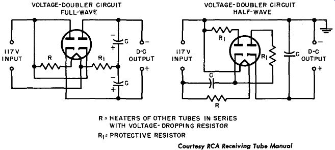
Fig. 13. Transformerless voltage doubler.
This polarity of dc voltage between heater and cathode is in the worst direction for tube reliability and is not recommended by manufacturers. The half-wave doubler (Fig. 13, right) overcomes this difficulty by making the negative terminal common with one side of the AC line.
15. Voltage-Tripler Circuit
The cascade voltage doubler can be combined in series with a half-wave rectifier to provide a DC output voltage that is three times the peak of the AC input voltage. A cascade voltage tripler is shown in Fig. 14. The input voltage may be supplied from a transformer or directly from the AC supply line.
Diodes V1 and V2 evidently comprise a half-wave voltage doubler which delivers an output voltage across C2 equal to 2E or twice the peak value (E) of the applied AC input voltage. In addition, half-wave rectifier V3 produces across C3 a voltage equal to the peak value (E) of the applied AC input voltage. The voltages across capacitors C2 and C3 are added in series, and the no-load DC output voltage is three times the peak input voltage. The voltage drops off rapidly when load current is drawn.
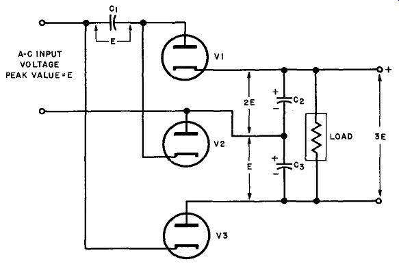
Fig. 14. Schematic of a cascade voltage-tripler circuit.
16. Voltage-Quadrupler Circuit
By combining two cascade voltage doublers in series, a voltage quadrupler circuit is obtained, as is illustrated in Fig. 15. Here two half-wave (cascade) doublers are fed from a common source (either a transformer or the AC line) so that their output voltages add in series. Note that the voltage across C1 equals the peak of the input voltage (E) while the voltage across C2 is equal to twice the peak voltage, or 2E. The voltage across C3 and C4 in series (or across the load) thus approaches four times the peak value of the AC supply voltage, when no load current is drawn.
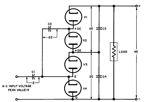
Fig. 15. Two voltage doublers shown as a cascode voltage quadrupler.
In theory, cascade voltage doublers may be added in series indefinitely to produce progressively higher output voltages. Since a voltage quadrupler will deliver a no-load DC output voltage of 4 x 1.414 or about 5.65 times the rms value of the AC source voltage, two quadrupler in series should produce an output voltage approximately 11 times the rms value of the AC input voltage. For a 117-volt AC line, this would result in a DC output voltage of about 1,300 volts, which would be nice work if you could get it.
In practice, however, it is found that the quadrupler presents a technical and economical limit of attainable voltage multiplication. As it attempts to increase the multiplication, the regulation of the system becomes progressively poorer, so that the attained output voltage drops off rapidly with even small load-current increases. The voltage stress across the series capacitors becomes increasingly great, requiring expensive units with high voltage ratings. Also, since the peak current through the rectifier must be limited to the rated values, the possible load current that can be supplied by the tubes becomes less with increasing multiplication. Finally, the cathodes of the tubes must be well isolated from each other, since they are at different potentials with respect to each other. This becomes increasingly difficult as the number of tubes is made larger. Despite these objections, voltage-multiplying circuits using metallic-oxide rectifiers and crystal diodes are quite popular for low-current applications, such as TV power supplies.
17. Review Questions
(1) Draw the circuit of a half-wave rectifier and explain its operation.
Assign a typical value to the AC input voltage and compute the DC output voltage.
(2) Explain the advantages of a full-wave rectifier over that of the half wave type. What is the ratio of the average to the peak current or voltage? The rms voltage to the DC output voltage?
(3) Define the following terms: regulation; ripple frequency; DC magnetization of core; step-up ratio; rms , peak , and average values of voltage and current; no-load current.
(4) Using a tube manual, select a full-wave rectifier tube, assign a value to the transformer secondary voltage and compute the no-load DC output voltage.
(5) Explain the operation of a bridge-type rectifier and state its advantages and disadvantages.
(6) What is the ratio of the average DC output voltage to the rms value of the transformer secondary voltage in a bridge rectifier circuit?
(7) Why are bridge circuits using metallic-oxide rectifiers and crystal diodes popular?
(8) What is the basic principle of voltage-multiplying circuits?
(9) Draw the circuit of a full-wave voltage doubler and explain its operation.
(10) Compare the operation of a half-wave doubler with that of a full-wave type; compare their regulation and other features.
(11) Explain the operation and features of triplers and quadruplers.
(12) Draw a voltage multiplier that will have an output voltage equal to seven times the peak value of the AC input voltage.