Link | Class D Citizens band communication takes place in the 27 MHz band. At this comparatively low frequency, radio waves can be radiated in two ways. One is the sky wave. Radio waves are radiated out at an upward angle and are reflected back by the ionosphere. Sky-wave signals can reach out several thou sands of miles ( Fig. 12-1) . Communication by the sky wave is illegal to CB equipment users.
The other form is the ground wave, which is radiation al most parallel to the plane of the earth's surface. This is like the radiation of tv signals at the higher frequencies described in earlier sections of this guide. The communication path for the ground wave is almost line-of-sight ( Fig. 12-2). Since communication is limited to ground-wave radiation, it becomes necessary to try to accomplish two conditions. That is, use the highest possible gain antenna, and mount it as high as possible. If communication over short distances meets requirements, it is not necessary to use great heights. But the higher the antenna, the farther out is the horizon, and the greater the distance of communication.
Since Citizens band communication is available to every citizen of the United States, without examination, the FCC felt some limits must be placed on communication range to reduce as much as possible interference between stations. This was in anticipation of thousands of stations coming on the air, a fore cast that was realized. The limits are to the power of the transmitter ( five watts input to the final stage), and the height of the antenna.
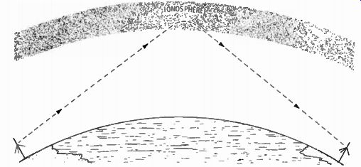
Fig. 12-1. Sky-wave communication.
HEIGHT
Section 95.37 of FCC Regulations on Class D CB says that the antenna and its support must not be more than 20 feet above ground or an existing structure on which it may be mounted; nor can it be above the top of an existing mast now supporting some other communications antenna. The height of an omnidirectional antenna and its support must not exceed 60 feet above ground.
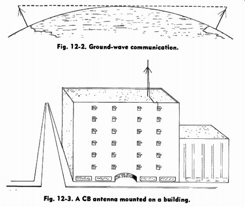
Fig. 12-2. Ground-wave communication.
Fig. 12-3. A CB antenna mounted on a building.
For a business with offices in a multi-story building even the 20-foot limit offers excellent opportunities for a high antenna, with excellent coverage possibilities. ( Fig. 12-3). The man who puts a CB system in his home and car is limited to the 20 feet above his home. For communication between home and car within a range of 5 to 20 miles, this may be sufficient (Fig. 12-4). While the use of a tall building for an antenna offers the advantage of height, there are some offsetting disadvantages that must be considered. All feed lines have some losses, some more than others. If the transmitter is far from the antenna, on the first floor of a 10-story building for example, the losses could be considerable. The most popular type of feedline cable for base stations is type RG-8/U, a heavy-duty coaxial cable, 0.4 inch in diameter. This cable has a loss factor of 1 dB per hundred feet at 30 MHz. Assuming about 200 feet of cable are used to reach from the first floor to the roof of the above example, plus some to reach the antenna set in from the edge of the building and to reach to the transmitter, total loss is 2 dB. This converts to a 37% power loss. However, the advantage of height overcomes this loss in net coverage. Using the lighter cable, RG-58/U, the loss due to the use of a long cable becomes significant. RG-58/U cable has a rated loss of 1.95 dB per hundred feet. At 200 feet this converts to about a 60% loss.
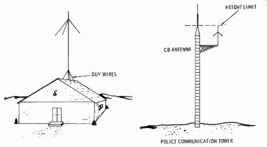
Fig. 12-4. Roof mounted CB antenna.
Fig. 12-5. A CB antenna mounted on a police communication tower.
In other words, only about 40% of the power fed to the cable by the transmitter ever reaches the antenna. Obviously, in this example, investment in the heavier cable, or locating the station in an upper floor of the building, is worthwhile.
As a general rule, the heavier coaxial cable is nearly always used for base station installations. The lighter cable is used for mobile installations.
The "top of an existing mast" mentioned before deserves some clarification, using an example. CB emergency groups are frequently working with local police departments. A CB base station antenna may be installed on the same tower supporting the police transmitting antenna, thus providing even greater height than the 20-foot limit ( Fig. 12-5) . Under this condition, the top of the CB antenna must not be above the top of the mast structure. That means the base of the antenna must be mounted about nine feet below the top of the mast on an extension arm.
HOME ROOF MOUNTING
CB base station antennas mount to the same type of mast as tv antennas. The U-bolt mounting clamps are the same. Any of the methods of mounting described in Section 7 for tv antenna mounting also apply to CB antennas. The antennas are made of aluminum tubing and are very light. They even have less wind resistance than a tv antenna.
Mast heights may be anywhere from five feet to the 20-foot legal limit. Five- or ten-foot masts are mounted in the same manner as for tv antennas, but 20-foot masts should include guy wires about half-way up ( Fig. 12-4). Guying rings are available which slip onto the mast and fasten near the center.
The rings contain holes for threading the guy wires through them. Use three guy wires. Forming a triangle, bring the wires down to heavy-duty screw hooks or rings. These should be screwed into the roof at points where they will reach down to the roof rafters, for a secure hold.
The step-by-step installation information that follows is based on installing an Archer ground plane CB base-station antenna. This is an inexpensive antenna but effective in performing as a standard ground plane antenna. It is all-aluminum in construction and includes a built-in jack for accepting the standard PL-259 type plug.
The antenna is supplied in knockdown form, as are all such antennas. It consists of eight aluminum rods, about four feet long and four a little longer. The shorter rods are smaller in diameter and fit into the longer rods. Together they make up the quarter-wavelength for each element. The rods and mounting bracket are predrilled, and all hardware is furnished, ...
--------------
AS II UNPACK THE ANTENNA AND BECOME FAMILIAR WITH THE PARTS IN THE ILLUSTRATIONS AND IN THE PARTS LIST. I I ASSEMBLE THE 7/16 RADIATOR TUBE IWITH BASE INSULATOR/ AND 3/8 TUBE AS SHOWN IN FIGURE 1.
II ASSEMBLE THE THREE OTHER 8 7116 AND 3/8 RADIAL TUBES IN ASIMILAR MANNER.
ATTACH THE THREE RADIAL TUBING ASSEMBLIES TO THE BRACKET AS IN FIGURE 3.
II ASSEMBLE RADIATOR TUBE ASSEMBLY IWITH BASE INSULATOR) INTO BASE BRACKET AS IN FIGURE 2.
INSTALLAT ION, I 1 INSERT THE U BOLT IN ITS HOLES. PUT ON THE LOCKWASHFRS AND START THE NUTS. II ATTACH THE COAX TO THE ANTENNA USING A PL - 259 CONNECTOR AND SEAL THE CONNECTION WITH PLY 0- BOND OR SOME SIMILAR PRODUCT.
PLACE THE ANTENNA ON THE MAST SO THE TOP OF THE MAST IS EVEN WITH THE TOP OF THE BRACKET. ( FIGURE 41 II TAPE THE COAX TO THE MAST EVERY FEW FEET
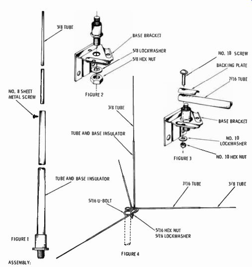
Fig. 12-6. Antenna assembly instructions.
------------------------------
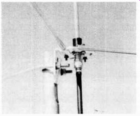
Fig. 12-7. Closeup of lead- in- and antenna mounting.
... as well as instructions for assembly. Self-tapping screws are supplied for the two lengths of rods. They have a hex head and are slotted. Either a screwdriver or a %-inch hex driver may be used-the latter is easier to use. Only a minimum of simple tools are needed altogether.
The far end of the larger rods are predrilled to take No. 10 machine screws; used to assemble the rods to the base plate.
Lock washers are supplied for them and for the threaded U bolt, which goes around the mast. Backing plates are used over the rods at the base plate under the screw heads. This gives added strength to rod assemblies.
The instructions are very easy to follow ( Fig. 12-6). They are given in words and sketches. Once they are read over, and the parts are inspected carefully as the instructions are read, assembly becomes automatic.
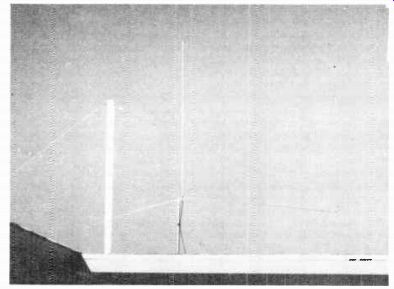
Fig. 12-8. Completed ground- plane antenna.
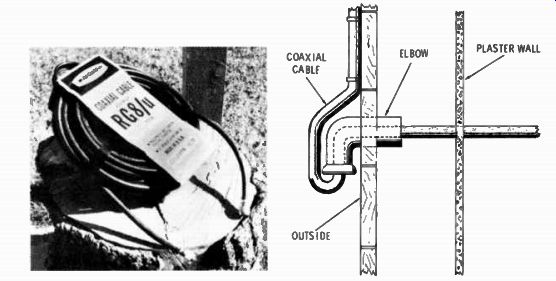
Fig. 12-9. A 50- ft. length of coaxial cable. Fig. 12-10. Running coaxial
cable through a wall.
Assembly may be done on the ground, or on the roof. It is easier on the ground. While the completed antenna is very light, it is a bit cumbersome to take up onto the roof with its nine-foot spider legs going out in all directions. If assembled on the roof, care must be taken to be sure small parts don't roll off.
The U-bolt clamps around the mast. Fig. 12-7 shows this in closeup. Fig. 12-8 shows the completed antenna, ready to be put into operation.
CONNECTING THE FEEDLINE
The feedpoint of a ground-plane antenna is around 50 ohms in impedance. The coaxial cable mentioned in Section 11 is the choice for feeding the antenna from the transceiver, and they have an impedance of 52 ohms which is right for the CB antenna. These are RG-8/U heavy-duty cables with an outer diameter of 0.4 inch, and RG-58/U cables with an outer diameter of 0.2 inch. The heavier is preferred for base station use.
Coaxial cable may be purchased in any length from bulk stock and in precut lengths in packages. The best way to buy it is in precut lengths with connectors already installed, for home use such as the antenna installation example just described. These are packaged in 50-foot lengths ( Fig. 12-9). This cable includes two PL-259 type plugs already installed on the ends. Its length is just about right for the average home installation.
Connect the cable plug to the antenna as shown in the closeup view of Fig. 12-7. Bring it straight down and tape it to the mast at one or two points, depending on the length of the mast.
Run it into the house about the same as you would tv cable, except that the standoff insulators made for tv cables are too small to take RG-8/U. It does not matter if the cable is near metal, because it has a shield under the outer cover. Any method of securing it to the house or building will do as long as the cable is not punctured in the process.
One of the best methods of bringing this cable into the house is through a hole in the wall opposite the operating position. A plumbing elbow whose inside diameter is at least twice the outside diameter of the cable should be installed with the outside opening facing downward (Fig. 12-10). This makes a waterproof entrance. Once brought through, the inside wall of the hole may be plastered around the cable to keep out the cold winter winds.
If the 50-foot cable is a bit longer than needed, just coil up the remainder under the operating table. There is not enough loss in the use of a small extra amount to warrant cutting it to exact length and installing a plug. There is only a 12% loss in the entire length of 50 feet of RG-8/U cable, so a few extra feet over will represent only a small percentage of the 12 %. The other end of the cable with its plug installed is merely screwed onto the output terminal of the transceiver or whatever CB equipment is used.
The end of this section shows how to connect PL-259 plugs to cables cut to length.
GROUNDING FOR PROTECTION
Unlike a tv antenna, a CB antenna has a vertical element that reaches up fairly high into the sky. This vertical element is insulated from the mounting plate and the mast. It connects to the center conductor of the cable feeding the antenna. This means that grounding the mast, as in tv installations, is not enough for a CB antenna. Instead, the center-insulated element must be protected from lightning.
Fig. 12-11 shows a lightning arrester made for coaxial cable.
There is a small spark gap between the outer shell and the inner conductor. Since CB power is low, the gap can be narrow without the transmitter power jumping it, but any static charge on the antenna will.
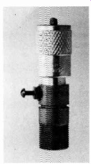
Fig. 12-11. Coaxial lightning arrester.
This coaxial lightning-arrester has a PL-259 plug at one end and a SO-239 socket at the other. It connects between the cable and the antenna, at the antenna. A heavy ground wire, usually aluminum, is connected to the screw on the side of the shell and run to a ground rod in the earth, the same as for tv antenna protection.
When the CB antenna is completely installed, it is well to give all connectors a coating of Ply-O-Bond and smear all hard ware with some silastic rubber or silicone seal. These will seal those parts against the effects of the atmosphere, and lengthen the life of the antenna.
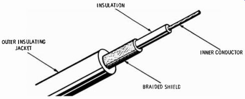
Fig. 12-12. Coaxial cable prepared for soldering to connector.
OUTER INSULATING JACKET BRAIDED SHIELL INNER CONDUCTOR
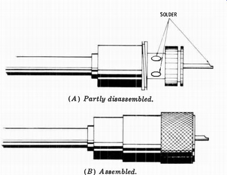
Fig. 12-13. Coaxial cable connector. (A) Partly disassembled. (B) Assembled.
INSTALLING COAXIAL CABLE CONNECTORS
When bulk coaxial cable is used, the ends must be dressed, and PL-259 plugs installed onto the ends. This takes some dexterity and some experience in soldering, although there are some solderless types of plugs.
The sketch of Fig. 12-12 shows how the ends of the cable are dressed. The inner conductor is soldered to the center pin of the plug. Since the pin protrudes out slightly in front of the shell, the inner conductor of the cable is made slightly longer than the rest of the cable parts. The braided outer conductor is soldered to the shell of the plug. The length of each cut on the cable is easily determined by laying it against the plug.
Remove the outer screw from the plug, and slide the plug onto the cable, well below the end. Insert the cable into the plug, and solder the center conductor to the pin of the plug.
Solder the braided shield to the neck of the outer shell through two of the holes in the neck. This is more easily done by pre tinning the shielded braid before inserting the cable. It will take a hot soldering iron to solder through the holes of the plug.
This is shown in Fig. 12-13A. Sketch B of this figure shows the completed assembly, after the outer screw-on shell is slid up and screwed back into place.
Next: INSTALLING THE MOBILE ANTENNA
Prev: Link | --CB ANTENNAS
AMAZON multi-meters discounts
AMAZON oscilloscope discounts
Also see:
Industrial Electronics (in the early 1960s)
199 Electronic Test & Alignment Techniques (1972)