All antennas must meet certain basic requirements, regard less of their use. Such basics as the need for resonance, impedance matching, proper feedline, and good construction are common to all. Even expensive broadcast antennas must meet these requirements.
That does not mean all antennas are alike; far from it. The CB antenna is quite different in many details from tv receiving antennas. A CB antenna is resonant to a very narrow band of frequencies. It is designed to receive and transmit. As a transmitting antenna, the legal transmitter power-input limit (five watts) is so small that not a bit can be wasted.
It is standard for the radio waves in the CB band to be vertically polarized. This means that both transmitting and receiving antennas are mounted vertically ( unlike tv antennas, whose elements are parallel with the plane of the earth's surface). One advantage of vertically polarized antennas is a better radiation pattern. A horizontal half-wave antenna has a figure 8 pattern (as described in Section 4 on tv antennas). A vertical antenna has a doughnut-shaped pattern and is therefore omnidirectional and has a low angle of radiation. This is ideal for communicating to all directions.
ANTENNA RESONANCE
An antenna is resonant to a radio frequency when its length is one-half the wavelength of that radio wave. Dividing 300 by the frequency in megahertz and dividing again by two will give the length in meters for a resonant antenna. The CB band extends from 26.965 MHz to 27.255 MHz, for 23 channels of operation. The center of the band is about 27.1 MHz. In the above formula a half-wave antenna is about 17% feet, after converting meters to feet. If you hold a 171 A-foot rod vertically in the air, you will have a half-wave antenna resonant in the CB band.
But a straight rod 17% feet long is hard to mount. Such an antenna would require a long, horizontal support at the middle of the antenna to hold it out so there would be no capacity effect to the mast. It might look something like Fig. 11-1. however there is a more practical approach. By bending the lower element half out and adding two more elements angled the same, we have what is called a ground-plane antenna, and one that can be mounted with the mast attached to the center ( Fig. 11-2). The vertical portion is a quarter-wave long, and the lower radials are each a quarter-wave long. Altogether they make a half-wave antenna.
The above may be compared to broadcast station antennas.
Because of the low frequencies of the broadcast band, only a quarter-wave mast is raised, and quarter-wave radial wires are buried in the ground, radiating out from the base of the antenna.
Another example of this is the mobile CB antenna. Its visible section is a quarter-wavelength in height. The car body is a random length quarter-wave for the other half of the antenna.
The car body becomes part of the antenna system.
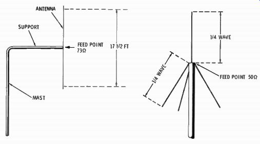
Fig. 11-1. An impractical 17.5 ft half-wave antenna.
Fig. 11-2. Diagram of a ground-plane antenna (quarter-wavelength).
FEEDING AND IMPEDANCE MATCHING
The center of a normal half-wave antenna is theoretically about 73 ohms. When the lower half is bent out, and the other elements added, the center impedance becomes more nearly 50 ohms. The center of the antenna is where it is fed energy from the transmitter, or from which the energy is taken for the receiver. It is electrically and mechanically a more convenient place to make the feedline connection.
Coaxial cable is always used for the feedline, because it has the advantage of the shielded cover which makes it easier to handle. Two types of cable are available with the proper characteristic impedance which eliminates the need for using transformers to change from one impedance to another. RG 8/ is a heavy-duty, low-loss coaxial cable with an impedance of 52 ohms. It is about 0.4 inch in diameter and is usually used for the base station antenna. RG 58/U is a thinner cable with the same impedance. It is about 0.2 inch in diameter, but has twice the loss of the heavier cable. It is used in a mobile installation because of its size. Since only a short run of it is needed in a mobile system, the added losses are of no consequence.
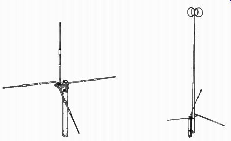
Fig. 11-3. Ground- plane antenna (quarter- wavelength). Fig. 11-4. Ground-
plane antenna (half- wavelength).
QUARTER-WAVE GROUND-PLANE ANTENNA
The evolution of the quarter-wave ground-plane antenna was described above. It is the most commonly used antenna for base station use. It is effective, light in weight, easy to put up, and economical.
Fig. 11-3 shows a ground-plane antenna, which sells for less than $10.00. It includes a built-in SO-239 connector which takes the PL-259 cable plug; now considered standard for connecting coaxial cable. Cable may be purchased with this plug already installed, simplifying installation. This antenna is used in the detailed installation instructions given in the next section for a base station.
HALF-WAVE GROUND-PLANE ANTENNA
The name of this antenna may sound like a misnomer, as any antenna must be a half-wave in length to resonate. But as we have learned, antennas have become named for the vertical element only, which is a quarter-wave long. The other quarter wave is found in the bent radials or the car body. The half wave ground-plane antenna is named for the vertical element also. However, with its ground-plane radials and a phasing transformer stub added into the total length, it is electrically a full-wavelength long. An antenna will not only resonate at a half wavelength, but at multiples of the half-wave in length, also. Thus, an antenna will resonate at or near 27 MHz if it is 17 1 / 4 feet, 35 feet, 52 1 / 4 feet, etc.
A half-wave ground-plane antenna is a quarter-wave ground plane with another half-wave length of vertical section added.
It is not the full physical length that is added, but a modification to prevent the antenna from becoming too long and unwieldy. The vertical portion is one-half wavelength long, the radials are one-quarter wavelength long, and the other quarter-wavelength is in a stub at the base, acting like a trans former. The Archer "Super Maxim" ( Fig. 11-4) is an antenna of this kind.
The Archer "Super Maxim" half-wave CB base-station antenna has been measured to have a gain of 3.75 dB over conventional quarter-wave antennas. This represents an increase of nearly 2 1/4 times in effective radiated power in transmitting and an equivalent increase in sensitivity in receiving. ( The dB is mathematically 10 times the log of the number representing the ratio of those two powers.)
CO-LINEAR ANTENNA
The colinear antenna is an improved method of adding an other half-wave in length to an antenna. The two half-wave lengths are "in phase," and result in improved directivity characteristics.
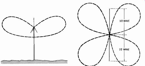
Fig. 11-5. Radiation pattern ( side view) of a half- wave antenna mounted
vertically.
Fig. 11-6. Overhead view of a full wave horizontal antenna radiation pattern.
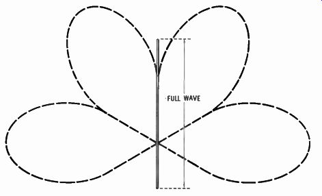
Fig. 11-7. Radiation pattern of a vertical full- wave antenna.
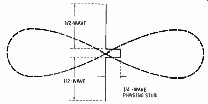
Fig. 11.8. Overhead view of two half- wave horizontal antennas radiation
pattern.
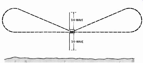
Fig. 11-9. Radiation pattern of o half-wave vertically mounted antenna.
Fig. 11-5 is the radiation pattern (side view) of a half-wave antenna mounted vertically. This is the pattern developed by the quarter-wave ground-plane antenna, which is really a half-wave antenna when the quarter-wave radials are included.
The doughnut-shaped pattern is distorted because of the effect of ground reflection. It develops from the figure 8 pattern of half-wave horizontal antennas.
Two half-wave antennas in line, or a full-wave horizontal antenna, have a double figure 8 pattern or a clover-leaf pattern (Fig. 11-6). A similar vertical antenna would have a pattern like Fig. 11-7, taking into account the reflection of the ground.
When two half-wave antennas are connected in line and a stub is added between, the two half-wave lengths become in phase, resulting in an elongated figure 8 pattern ( Fig. 11-8). Make this into a vertical antenna and note the pattern ( Fig. 11-9). Now we have improved low-angle radiation and an increase in radiated power.
Fig. 11-10 shows the Archer Colinear base-station antenna.
It has a measured effective increase in power over a regular half-wave type (quarter-wave ground-plane) of 4 dB. With the antenna five-eights of a wavelength long, we now have an equivalent to over 2% times the effective radiated power. To put it in another way, it is as though your 5-watt transmitter (the legal maximum power limit) had an input power of 12.55 watts. By making the upper vertical sections five-eights wavelength long, the radials one-quarter wavelength long, and the balance in a phasing network at the base, the length of the vertical element is kept to a very reasonable span of 19 feet, 10 inches.
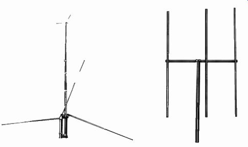
Fig. 11-10. Colinear base- station antenna. Fig. 11-11. " Crossbow III" beam
antenna.
BEAM ANTENNA
Talk to any amateur radio man and he will tell you, when physical dimensions permit, his most effective antenna is a beam antenna. This is a type of construction similar to that described for tv antennas earlier in this guide, but with a higher efficiency due to the much narrower bandwidth over which they operate. The increased forward gain and the higher front to-back ratio results in an effective power gain many times that of a standard half-wave antenna.
The Archer "Crossbow III" CB beam antenna shown in Fig. 11-11 is a three-element array on a 12-foot boom. It has a for ward gain of 9 dB, which means that the 5-watt input to a CB transceiver becomes equivalent to 40 watts into an ordinary half-wave antenna. For a serious CB enthusiast this is a considerable increase and well worth the added investment. The front-to-back ratio is 25 dB, which means the antenna has a 25 dB higher sensitivity in pickup from the front than from the rear. This is a great help in reducing the received level of interfering stations which may be in the opposite direction as well as increasing the signal of the desired station.
Unless one is interested in only communicating between two fixed points, the beam must also be mounted atop a rotator, like one of those described in Section 9. For full efficiency, wide area coverage, it is necessary to be able to turn the beam to the direction of communication.
MOBILE ANTENNAS

Fig. 11-12. Roof antenna. Fig. 11-13. Cowl or trunk lid antenna.
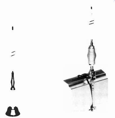
Fig. 11-14. A trunk lid antenna incorporating a base loading coil. Fig. 11-15.
Single- strap bumper mount antenna.
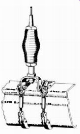
Fig. 11-16. Double-chain system for mounting on a bumper.
The greatest feature in operating Citizens band is the ability to communicate between a car and home or office, at a small investment in equipment. Most CB transceivers today use solid state circuitry, are small, and are easily mounted under the dash of a car. All that is necessary is to mount an antenna and connect it.
Most CB mobile antennas are pretty much alike, differing only in details. The similarity lies in the use of a quarter-wave vertical element, with the car body acting as the other quarter wave, for a half-wave theoretical antenna. They differ in the method of mounting, in general construction, and in the use of loading coils in some cases to reduce the length of the vertical element.
The first consideration in the selection of a mobile antenna is to decide where it is to be mounted on the car. The best place electrically is on top of the car roof. This results in the best omnidirectional pattern because the mass of the car body is evenly distributed under the antenna. The drawback in roof mounting is the total height above the car, which might interfere with underpasses or garage entries. Fig. 11-12 is a sketch of the Archer "Shorty" roof antenna. It has a coil in the center which adds inductance to the antenna and makes it possible to reduce the physical length. This antenna is only 18 inches high.
It has a spring at the base to allow the antenna to bend if it hits an obstruction. It requires drilling a 1/4 inch hole in the roof of the car and running the lead-in behind the roof upholstering, like the wiring to the dome light.
The second best antenna location is on the trunk lid. With trunk-lid mounting the radiation pattern is not as circular as for roof mounting, but nearly so. Fig. 11-13 is a photo of an antenna which also has a center-loaded coil, reducing the overall length to 37 inches. This antenna may also be mounted onto the cowl or fender. It has a swivel mount to allow for adjustment to the slope of the cowl or trunk.
Fig. 11-14 is a photo of an antenna designed to be fastened to the edge of the trunk lid, without drilling holes. A base loading coil reduces the vertical element length.
Perhaps the most popular method of mounting a mobile antenna is on the bumper. It is the easiest place to mount an antenna, and one which most easily permits its removal without leaving telltale marks. Fig. 11-15 shows the Archer bumper mount antenna using a single strap for mounting. The vertical element is made of fiberglass with the quarter-wave inside the fiberglass.
The antenna in Fig. 11-16 uses a double chain system of mounting to the bumper. This one and the one shown in Fig. 11-15 have springs at the bottom to allow easy bending when hitting overhead obstructions. This antenna has a 102-inch vertical element.
While bumper mounting is the easiest, it also results in the greatest distortion of the radiation pattern. If it is mounted on the left side of the rear bumper, there is a slight beaming effect towards the right front.
This antenna, and another shorty for mounting to the rain gutter for temporary installations, are the subject of a detailed how-to-install-it story in Section 13.
Next: INSTALLING FIXED STATION CB ANTENNAS
Prev: ACCESSORIES FOR BETTER TV ENJOYMENT
AMAZON multi-meters discounts
AMAZON oscilloscope discounts
Also see:
Industrial Electronics (in the early 1960s)
199 Electronic Test & Alignment Techniques (1972)