There is a wide selection of mobile antennas for CB use. The basic kinds were described in Section 11. Each one comes with complete instructions on how to mount them on a car. Considering that one is working at ground level, it is not difficult to install a mobile CB antenna. However, those that mount on a metal surface pose a problem in the need to cut a large hole in the car's fender or roof. These can be cut by using an electric drill to make a small starting hole, then using a hand brace with a tapered reamer for enlarging.
There are alternatives to drilling into the car body. The two mobile antennas, whose installation is described in the following paragraphs, require no drilling, and are easily removable for use on another car.
GUTTER-MOUNT ANTENNA
The simplest antenna mount is to use the rain gutter at the side roof line of the car. The antenna merely clamps to the rolled-up edge of the rain gutter. The accompanying illustrations cover the installation of the Radio Shack gutter-mount antenna. It is only 18 inches high, but has a loading coil that makes it an electrical 1/4 wave long. It has attached to it a length of RG-58/U cable which has a PL-259 plug attached on the end.
It comes ready to be immediately plugged into the CB transceiver in the car.
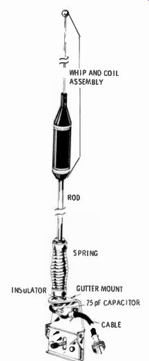
Fig. 13-1. Gutter- mount antenna construction.
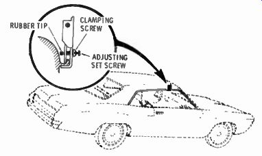
Fig. 13-2. Gutter clamp.
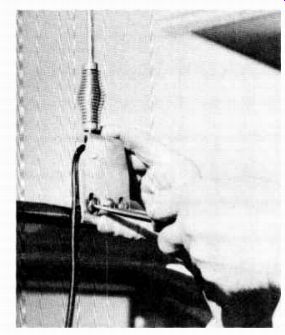
Fig. 13-3. Mounting the antenna.
Because of its small size and ease of installation and removal, the gutter-mount antenna is intended for temporary use. Al though its short length reduces the risk of hitting low over-passes and other solid obstructions, a spring at the bottom will give when obstructions, such as low overhanging tree branches, are hit, with no damage to the antenna.
Even though this resonates in the CB band, an antenna as short as this must not be expected to give the results of one whose physical length is the full 1 / 4 wave for resonating. For a temporary antenna, however, results are good.
Fig. 13-1 shows the details of the gutter-mount antenna.
Fig. 13-2 is a closeup of the clamp which holds to the inside of the gutter. For mounting, the clamp is first loosened, then fitted over the gutter and tightened. When held firmly, there is a tendency for the antenna to bend towards the car body. An adjusting screw centered between the clamping screws is turned in until its rubber tip presses against the car body to push the antenna into an upright position.
Fig. 13-3 shows the antenna being mounted to the gutter of a car. The cable is fed in through the window, and the plug screwed into the antenna socket of the CB transceiver.
BUMPER-MOUNT ANTENNA
Because the bumper of a car is at a low level, an antenna mounted to it can be a full physical 1/4-wavelength without the use of loading coils. While excellent results are obtained, there is some directional effect due to the mass of the car body. The ideal installation, electrically, would be on the top of the car body, in the center of the roof. But an antenna physically a quarter-wave in length would extend nine feet above the roof, which makes it rather impractical.
The bumper-mount antenna to be described here uses a double-chain mounting system, which is more rigid than a ...
----------
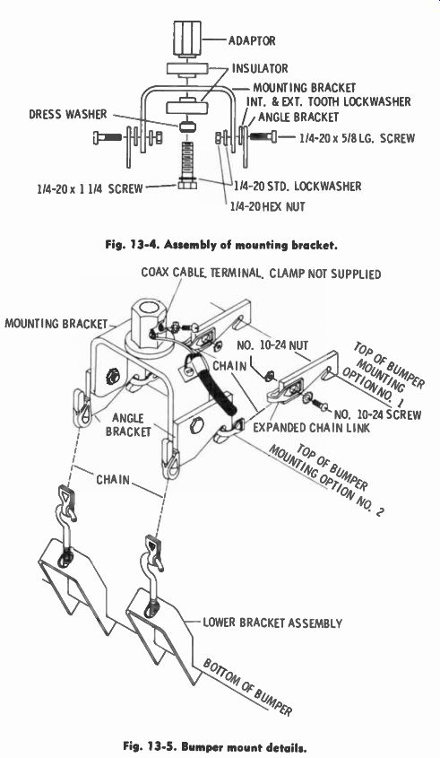
Fig. 13-4. Assembly of mounting bracket.
COAX CABLE. TERMINAL, CLAMP NOT SUPPLIED
- ADAPTOR DRESS WASHER Pm' T. 1 1/4-20 x 1 1/4 SCREW - INSULATOR
- MOUNTING BRACKET INT. & EXT. TOOTH LOCKWASHER
ANGLE BRACKET
- 1/4-20 x 5/8 LG. SCREW 1/4-20 STD. LOCKWASHER 1/4-20 HEX NUT
Fig. 13-5. Bumper mount details.
COAX CABLE. TERMINAL, CLAMP NOT SUPPLIED MOUNTING BRACKET
ANGLE BRACKET
NO. 10-24 SCREW EXPANDED CHAIN LINK
LOWER BRACKET ASSEMBLY
-----------
...single chain. The whip is 108 inches long with spring, and includes enough chain links for holding to any size bumper.
A package of parts is supplied with the bumper-mounted antenna. The parts are steel with heavy cadmium plating. The mounting hardware is of heavy construction. A spring permits the antenna to bend if it hits an overhead obstruction.
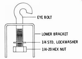
Fig. 13-6. Lower bracket assembly.
EYE BOLT; - LOWER BRACKET 1/4 STD. LOCKWASHER 1/4-20 HEX NUT
Assemble the mounting bracket as shown in Fig. 13-4. Mount the angle brackets to the mounting bracket, leaving the 1 A-20 screws and hex nuts loose, as shown in Fig. 13-4. Examine the bumper to determine whether mounting option No. 1 or mounting option No. 2 shown in Fig. 13-5 adapts to your bumper.
Mount the bumper tie assembly to the bumper using the mounting option chosen. Either of the mounting chains provided may require shortening, as shown in Fig. 13-5. Assemble the lower bracket assembly ( 2 required) as shown in Fig. 13-6. Leave the 1 / 4-20 hex nuts near the end of the eye bolts to allow for secure tightening of bumper mount. After tightening bumper mount assembly securely to bumper, align mounting bracket for vertical mounting.
Strip the protective plastic ferrule off the threads of the spring and screw the spring into place onto the antenna-mounting base of the bracket. Strip the protective plastic off the screw of the antenna rod and screw the rod into the top of the spring.
Strip a length of RG-58/U cable and solder the lugs onto the center conductor, and the outer shield. Secure the cable to the antenna bracket. Then connect the outer shield to the U-shaped bracket (ground) and the inner conductor to the center post.
The center antenna mounting post is insulated from the bracket.
Recheck your work to make sure it is secure and that no part of the vertical section of the antenna, including the spring and base of the bracket, touches any part of the car. It is better to adjust the bracket slightly off the vertical than risk the antenna parts touching the car and shorting out.
The feeder cable can be run to the transceiver in either of two methods. One is to run it under the car chassis, into the motor compartment, and back through the firewall to the transceiver. A good grade of plastic tape should be used to fasten the cable to nonmoving parts of the chassis underneath. The other method is to go into the trunk, through the wall between the trunk and the back seat, and under the edge of the carpet to the transceiver. This is the method used most, and is rather easy to do. The cable is less than 1 / 4 - inch thick and easily fits along the edge under the carpeting.
CHECKING MOBILE ANTENNA PERFORMANCE
If you have read through the tv sections of this guide, you will remember references to impedance matching and standing waves on the feeder. Impedance matching between the antenna and the transceiver is important in CB equipment as well, and especially for mobile installations, because of the low height and the need to get every milliwatt of energy into the air.
The output of a transceiver in its transmit position is de signed for a 50-ohm load. The characteristic impedance of RG-58/U cable is 50 to 52 ohms. If the antenna connected to the cable is resonant, its load impedance is very nearly 50 ohms.
Therefore, a resonant antenna is the proper load for the transceiver, and no adjustments are necessary.
An antenna which is resonant at a frequency other than the operating frequency will not "look" like a proper load to the transceiver, and there will be a loss of output power due to the mismatch. An antenna can be made to resonate at the operating frequency by the simple means of changing its length. But you must first know whether the antenna is or is not resonant, and if not, whether you are nearing resonance as you adjust its length. This is done by making measurements with an inexpensive instrument called a CB tester.
The photo of Fig. 13-6 shows the Realistic CB Tester. It requires no external power to operate it. It works from the power output of the transceiver. It is one of several standing wave ratio ( swr) instruments ; the more expensive ones measure the swr of high-powered transmitters. Adjusting for minimum swr, adjusts for resonance and impedance match between transmitter and antenna. The Realistic unit does more than measure swr. It also measures percent of modulation. It may be connected at the transceiver and left in the feeder line permanently for observation of antenna performance and modulation.
Connect the CB tester between the feeder line and the antenna. Turn the transceiver on and lock it in transmit position.
Have the channel selector on a channel near the center of the CB band. Set the center knob of the CB tester on " swr cal" and adjust the right-hand knob for full scale setting of the meter needle. Turn the center knob to swr and read the meter. If it reads between 1 : 1 and 1 : 1.2 you are close enough to resonance for excellent performance and no adjustment need be made to the antenna. If the swr reading is higher than 1 : 2 some antenna length adjustment is necessary.
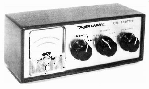
Fig. 13-7. CB tester.
The gutter-mount antenna described above is easy to adjust.
Loosen the knurled lock nut at the bottom of the coil and slide the coil up or down on the lower section of the vertical portion of the rod. With each adjustment of length, make a new measurement of swr. Each time the swr is measured the instrument must be recalibrated.
The bumper-mounted antenna is a full 108 inches long with the spring in place (the spring adds 6 inches to the length) . At its full length, it is nearly resonant to 26 MHz. To test this antenna, set up the swr bridge ( CB tester) as for the gutter-mounted antenna. The swr will probably be above 1:2. Using heavy-duty wire cutters, or a hack saw, cut one-half inch off the top and make a new measurement. If still not close enough, repeat the cutting operation and re-measure.
It may take as many as 10 of these cuts to reach resonance, but it is advisable to take it a little at a time to prevent going past the point of best swr.
Prev: INSTALLING FIXED STATION CB ANTENNAS
AMAZON multi-meters discounts
AMAZON oscilloscope discounts
Also see:
Industrial Electronics (in the early 1960s)
199 Electronic Test & Alignment Techniques (1972)